

American Fibertek RR-3340 User Manual
© Copyright 2007, American Fibertek, Inc. 0501JD
Instruction Manual
RR-3340
Video Receiver With
Bi-directional RS232 And
Bi-directional RS422

INSTALLATION AND OPERATION INSTRUCTIONS
INTRODUCTION
Thank you for purchasing your American Fibertek RR-3340 singlemode video receiver with bi-directional RS232
and bi-directional RS422. Please take a few minutes to read these installation instructions in order to obtain the
maximum performance from this product.
FUNCTIONAL DESCRIPTION
The RR-3340 operates as half of a transmitter / receiver pair for the transmission of a baseband NTSC, PAL,
RS170, or RS343 video signal with bi-directional RS232 data and bi-directional RS422. It is designed to operate
with the MT-3340-12VDC or RT-3340 video transmitter over one singlemode fiber optic cable.
The RR-3340 converts a RS232 data input and a RS422 data input into an optical output using a 1550 nm
wavelength source. The RR-3340 also converts an optical input signal returning on the same fiber into a single
video output, a RS232 data output, and a RS422 data output using a 1310 nm wavelength detector. The 3340
Series product is designed to operate over an optical loss budget range of 0 to 21 dB. The RR-3340 operates on
9 um singlemode fiber. Refer to the data sheets for detailed performance specifications.
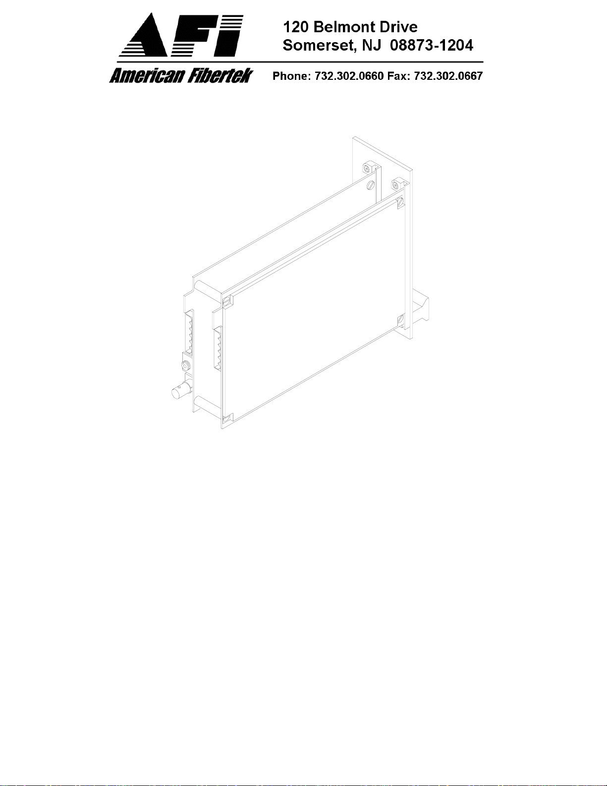
This unit is designed for rack mounting in any of the four American Fibertek subracks available. The subrack
models are SR-20/1, SR-20R/1, SR-20/2, and SR-20D/2. Slide in rack mounting, detachable terminal blocks,
and a LED indicator provide for easy installation and monitoring of video, data, and optical power.
The RR-3340 is designed for rack mounting only. For a modular stand alone version please see the MR-3340.
INSTALLATION
THIS INSTALLATION SHOULD BE MADE BY A QUALIFIED SERVICE PERSON AND SHOULD CONFORM
TO THE NATIONAL ELECTRICAL CODE, ANSI/NFPA 70 AND LOCAL CODES.
The unit slides into any two adjacent slots in the SR-20, SR-20R, or SR-20D subrack. Use a small screwdriver
to push and lock the four ¼ turn fasteners into place.
POWER SOURCE
Power to the unit is supplied by the subrack. Please refer to the SR-20, SR-20R, SR20D and PSR-2 instructions
for further details.
POWER CONNECTION
Power is supplied to the unit via a four finger backplane connector. The RR-3340 can be inserted into the
subrack or removed from the subrack with power applied to the backplane.
2
 Loading...