

Page 1

Instruction Manual
RD-20D
AFINETY System
Status Monitoring
© Copyright 2005, American Fibertek, Inc. 0801JD/JPM
1
Page 2
Table of Contents
Functional Description................................................................................ 3
Installation.................................................................................................. 4
Admin Connection...................................................................................... 6
Menu System ............................................................................................. 7
IP Configuration ......................................................................................... 8
Admin Menu............................................................................................... 8
Monitor Menu ............................................................................................. 9
Email Menu ................................................................................................ 9
Web Browser Interface............................................................................. 10
GUI Interface............................................................................................ 11
Alarms...................................................................................................... 11
Warranty & Service Information................................................................ 12
2
Page 3

INTRODUCTION
Thank you for purchasing the RD-20D AFINETY status monitoring system with your
American Fibertek fiber optic communications system. Please take the time to fully read
and understand the information in this manual in order to obtain the maximum
performance from this product.
FUNCTIONAL DESCRIPTION
The RD-20D is a plug-in unit for the SR-20D subrack frame. It is used to gather status
information from companion fiber optic application cards within the same SR-20D. This
information is available to the user in text form through the admin Telnet or RS232 ports
or as a graphical presentation viewed via a web browser and Ethernet connection.
No application specific software is required in order to use the system. The interface is a
standard web browser available with all current personal computer operating systems or
as add on software components. The web host service has been tested on a variety of
web browsers including MS IE5 & 6, Mozilla, Netscape, Opera and Galleon. Various
operating systems have also been tested with superior results. These include MS
Windows 98, ME, NT4 SP6, 2000, XP, 2003 Server and Mandrake Linux 9.2 along with
various versions of Unix.
The AFINETY System allows a American Fibertek SR-20D subrack to be monitored
remotely, allowing a technician to see front panel LED status, signal and optical link
presence, and internal voltage and temperature conditions. The system may be
monitored from a PC connected to the RD-20D unit either by an Ethernet link or a
RS232 serial cable.
The AFINETY system consists of a SR-20D subrack, in which a RD-20D rack card is
installed. Rack cards which have the status monitor option installed will be automatically
recognized by the status monitor system when installed in the subrack. Rack cards
without the status monitor option installed will function when in stalled in a SR-20D
subrack, but will not be recognized or monitored by the status monitor system. If
multiple subracks are to be monitored, each will require its own RD-20D card.
The RD-20D status monitor will continuously check all monitored components in the
subrack for faults or alarm conditions, and will signal alarm conditions by closing a relay
contact, showing an alert on the screen of the monitoring PC, and optionally by sending
an email to a user-supplied address detailing the nature of the alarm condition.
3
Page 4
INSTALLATION
THE INSTALLATION OF THIS UNIT SHOULD BE MADE BY A QUALIFIED SERVICE
PERSON AND SHOULD CONFORM TO THE NATIONAL ELECTRICAL CODE,
ANSI/NFPA 70 AND LOCAL CODES.
The RD-20D occupies one slot of the SR-20D frame to be monitored. The unit may be
mounted into any slot. It is suggested that the unit be mounted adjacent to the PSR
power supply in the right hand slot number 1.
Align the unit with the gray card guides of the slot and slide it completely in until it stops
and the front panel meets the frame top and bottom rails. Use a small flat blade
screwdriver to push and twist the ¼ turn fasteners into place.
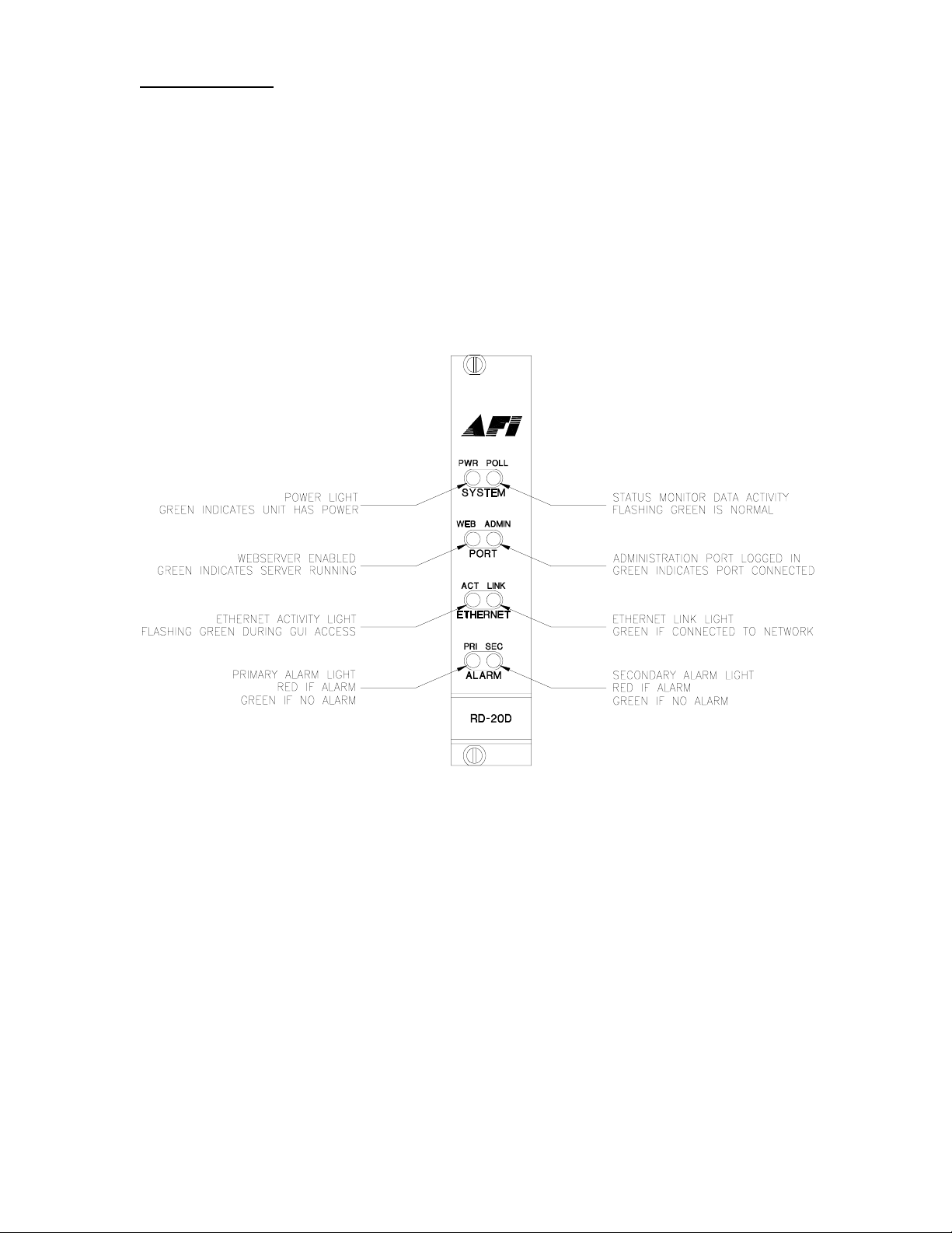
RD-20D Front Panel LED Indicators
4
Page 5

All status monitoring information is passed along the AFINET in the back plane of the
SR-20D. There are no additional connections required between units in the frame. The
rear of the RD-20D provides access to the I/O ports that include and RS232 DCE port
for configuration via a communications program such as Hyper-terminal, and a 10baseT
Ethernet port for administration via Telnet and connecting the webserver to the LAN or
directly to an administrative computer with an additional network card (not provided). A
4 pin Phoenix block type connector is provided for connection to normally open relay
contacts which signal detection of primary and secondary alarm conditions.
RD-20D Rear Electrical Connections
5
Page 6

ADMIN CONNECTION SETUP
The status monitoring system may be configured via Telnet on the Ethernet port or via
Windows Hyper Terminal on the RS232 port. Other RS232 communications programs
may also be used. The menu systems are the same for both of these text type
connections. The minimum configuration required is the IP Address and Subnet Mask.
See your network administrator for this information if you are not familiar with this
configuration requirement. The menu system is described in detail below.
RS232 Admin Port
Connect a computer or laptop to the RS232 port using a null-modem cable. Open your
communication program and hit <Enter>. The default logon appears asking first for the
Username (default “admin”) and then password (default “afinety”).
Ethernet Port
The Ethernet port is configured as an MDI configuration for directly connecting to a
network switch or hub with a standard Ethernet cable. To directly connect to a computer
network card or laptop port, a crossover cable will be required.
In installations that require a stand-alone admin console without connecting the RD-20D
to a local area network, it is recommended to install a network card in the admin
computer solely for this purpose. A crossover cable is then used to directly connect to
the RD-20D. The network parameters for the network card in the admin computer are
then set to:
IP Address: 192.168.100.2
Subnet mask: 255.255.255.0
Reboot the computer after installation if your operating system requires. The IP address
of the RD-20D and the Ethernet adapter need to be configured as to not interfere with
any network adapter already installed in the admin computer. See your network
administrator for more details. The IP address recommended above has been selected
to increase the probability of interoperability with most networks that may be connected
to other network cards in the administrator computer.
Telnet
For a first time connection via the Ethernet port it is recommended to directly connect a
computer or laptop to the port via a CAT5 crossover cable. This will allow IP
configuration to be performed before connecting to your LAN, avoiding possible IP
address conflicts. Using Telnet, “OPEN 192.168.100.10”. The default logon appears
asking first for the Username (default “admin”) and then password (default “afinety”).
6
Page 7

MENU SYSTEM
Top level menu commands may be executed by using the first two letters of the
command i.e. LO for LOGOUT or MO for MONITOR. Lower level commands require the
full command name to execute. Some commands require an entry (argument) to follow
the command on the same line.
MENU SYSTEMS OPTIONS
LOGOUT (LO) This command will log off the current user. To log back on the connection
will need to be re-established and the username and password will need to be entered.
IP (IP) The IP command menu gives access to setting the IP protocol setting required for
Ethernet communications. If you do not know the IP settings required to communicate on
your LAN, see your system administrator for details.
MONITOR (MO) The MONITOR command menu allows access via textual displays of
the status of all monitored parameters of the system. All status may be displayed or the
status of individual units may be displayed. Alarm conditions and limits may also be set
in this menu.
ADMIN (AD) Administrative settings are available in the ADMIN section. Here the
Username and Password may be configured along with the global settings of Site and
Rack Identification strings.
EMAIL (EM) Alarm instance reports can be sent to a single email address through this
setup. A domain name for the RD-20D is required along with a target email address. The
service may be started or stopped and notification timing parameters may be set.
7
Page 8

SETUP
The setup procedures are separated into two classes for clarity. IP & ADMIN menus are
for settings connection parameters for access via web or telnet/RS232. The MONITOR
menu is for viewing text displays of status information and setting user alarm levels and
priorities.
IP CONFIG Menu
IP n.n.n.n – Enter the command IP followed by the IP address to assign to this
Ethernet port in dotted quad format. (Default 192.168.100.10)
NETMASK n.n.n.n - Enter the command NETMASK followed by the Subnet mask
specification in dotted quad format. (Default 255.255.255.0)
GATEWAY n.n.n.n - Enter the command GATEWAY followed by the IP address
of the local area network Internet Gateway in dotted quad format. (Default
0.0.0.0)
NAMESERVER n.n.n.n - Enter the command NAMESERVER followed by the IP
address of the DNS server in dotted quad format. (Default 0.0.0.0) (Optional)
IPLOG – Lists the last 10 unique IP addresses accessing the webserver, most
recent first.
START – Starts the webserver.
STOP – Stops the webserver
SECURE – Sets the webserver to Secure Web Server Mode requiring a
Username and Password to gain access via the web interface.
UNSECURE - Sets the webserver to Un-secure Web Server Mode NOT requiring
a Username and Password to gain access via the web interface.
WEBUSER - Sets the webserver Username to be used in Secure Web Server
Mode
WEBPASS - Sets the webserver Password to be used in Secure Web Server
Mode
ADMIN Menu
Username - Sets the administrative port Username to be used via the Telnet or
RS232 port.
Password - Sets the administrative port Password to be used via the Telnet or
RS232 port
Site ID – Text string posted on the Web Interface identifying the site of the
installation.
Rack ID - Text string posted on the Web Interface identifying the specific rack at
the site of the installation.
TIMEZONE n - Sets the time zone, as an offset in hours from GMT.
8
Page 9

MONITOR Menu
UNITS - List all Model Numbers of units in the rack by slot #
UNIT n - Lists the monitored parameters and values for the unit in slot “n”
UNITNAME n – Set the name of the card for identification purposes. On the web
browser interface, this appears under the Card ID.
ALARMS – Presents number list of all rules currently programmed to test for
alarm conditions
DELALARM n – deletes the specified alarm rule
ADDALARM n – adds a new rule to the list of alarm rules. See the section on
alarms for alarm rule formatting
RESET – erases all alarm rules and replaces them with the default alarm
conditions. This takes about a minute, during which time the unit will not be able
to do anything else.
TEMPMODE n – used to specify if temperatures are displayed in Celsius or
Fahrenheit notation.
TIMEOUT n – sets the time after which a unit removed from the rack will be
removed from the GUI display.
EMAIL Menu
CONFIG – Shows the current configuration.
DOMAIN n – Enters the source domain name to be used when sending email
notifications.
EMAIL n – Email address to send notifications.
RETRY n – Sets the number of retries that the units attempts to send emails
Default value = 10.
DELAY n – Sets the delay time in seconds between email attempts. Default
value = 900 seconds.
START – Starts the email notification system.
STOP – Stops the email notification system.
9
Page 10

USING THE WEB BROWSER INTERFACE
Page Loading – At the admin computer, open a web browser and type the IP address of
the RD-20D in the URL dialog box. A graphical display is loaded showing the SR-20D
and the cards loaded into each slot. LED status is displayed and updated every few
seconds.
Unit Selection – Click on any unit to load a table of monitored parameters below in the
graphic.
Parameter Listing – All monitored parameters are listed in categorized tables. These will
vary depending upon the unit installed and the available information. All units monitor
temperature and power up time. Also displayed are the model number and serial number
of the card. Site ID and Rack ID are programmed via the admin interface and displayed
at the top of the table.
Alarm Indication – The word “ALARM” will appear in red at the bottom of a card that has
a parameter outside of the programmed limits. The RD-20D offers two contact closure
outputs for remoting the alarm signals. Each alarm can be identified as a primary or
secondary alarm. There is a corresponding contact for each alarm level, available on the
rear interface of the RD-20D plug-in card.
Local / Remote units Monitoring – On units which include a monitored remote module,
the monitored parameters from the remote unit will be shown in a separate table below
the local unit parameters. If the RD-20D is unable to connect to the remote module –
due to the optical cable being disconnected, power loss to the remote unit, or other
malfunction – the parameters for the remote unit will be shown as unknown.
10
Page 11

USING THE SERIAL PORT GUI INTERFACE
Application software is provided which can be used to access the monitor GUI through a
RS232 connection instead of an Ethernet connection. This software presents a
graphical interface similar to that displayed by the web browser GUI.
To use the serial port GUI application, connect an unused serial port on a Windows PC
to the management port on the RD-20D with a null-modem cable. This connection is the
same as that used to access the management interface of the RD-20D, although the
GUI application and the management port interface cannot be accessed simultaneously.
In order to use the serial port GUI, the management port must be logged out and the
terminal software used to access the management port must be closed. The Telnet
management port can be used while the serial port GUI is in use, but this is not
recommended, as system response time will be severely effected.
The serial port GUI displays all of the data shown by the web browser GUI, in a nearly
identical layout. The graphical representation of the subrack will be updated to match
the actual status of the monitored subrack, and detailed information on any unit in the
rack can be selected by clicking on that unit's graphic. The serial port application does
have additional menu choices used to select the serial port connection.
Under the application’s File menu are three menu items. The first leads to a submenu
which can be used to select which serial port the application should attempt to connect
to the RD-20D with, or which shows which port the application is using if it is already
connected. When the user selects one of the serial ports under the connection
submenu, the application will attempt to connect to the RD-20D on the selected port.
The second menu item commands the application software to disconnect from the RD20D and release the selected port if connected. The third option under the File menu
causes the application to disconnect from the port if connected, and then will close the
application.
If the application software is closed while still connected to the RD-20D, it will
automatically attempt to reconnect to the previously connected port when next opened.
If the serial port GUI application software is unable to access the selected serial port, is
unable to connect to the RD-20D on that port, or loses contact with a RD-20D, it will
display an error box and return to a disconnected state. To reconnect the user will have
to correct the cause of the loss of communication, and then select a port to reconnect on
under the connection submenu.
In addition to the status information from the RD-20D, the GUI will indicate if it is
connected or disconnected, and the port it is connected on if connected. When
disconnected, the GUI application will continue to display the status information received
just before disconnecting.
ALARM LIMITS
The RD-20D is pre-programmed with a set of basic alarm rules which will signal an
alarm in the event of any problems with the AFI hardware or the systems connected to it.
Alarms in the system are classified as Primary or Secondary alarms, with a LED
indicator and relay output for each alarm classification.
The signaling of a Primary alarm indicates that some part of the system is currently not
functioning and needs attending to. A Primary alarm will be indicated if any the subrack
power supply or any unit's internal power supplies are not producing the correct voltage,
or if any internal component is not operating properly, or if any video or optical link is
lost.
11
Page 12

A Secondary alarm indicates a condition that is not yet causing loss of system
functionality, but still may require a technician’s attention. A secondary alarm will be
indicated if the temperature inside the unit is below -40C or above 70C.
The customer can change the alarm rules through the management port if required.
This can be done to change individual out-of-range thresholds, change individual alarm
conditions from Primary to Secondary or Secondary to Primary, disable specific alarm
conditions, or add new alarm conditions for specific units as needed.
ALARM CONNECTIONS
The RD-20D has two relay contact outputs which close in the event of an alarm
condition, one Primary alarm and one for Secondary alarm. The relay contacts will close
within a few seconds of an alarm being detected and will remain closed until the alarm
condition is resolved.
ALARM EMAIL NOTIFICATION
The RD-20D can be configured to send an Email to a user-specified address
when an alarm occurs. Any change in alarm conditions – the triggering of any
individual primary or secondary alarm, the restoration of a previously triggered
alarm, or the removal of any of the monitored units from the system – will be
logged with the time of occurrence by the RD-20D. After a short period of time
(to allow multiple alarms to be sent in the same log) the unit will send an email to
the address previously specified by the user, and then clear the log. The unit will
then wait a user-specified time before sending any more emails, with any alarms
occurring in that time saved in the log.
LIFETIME WARRANTY INFORMATION
American Fibertek, Inc warrants that at the time of delivery the products delivered will be
free of defects in materials and workmanship. Defective products will be repaired or
replaced at the exclusive option of American Fibertek. A Return Material Authorization
(RMA) number is required to send the products back in case of return. All returns must
be shipped prepaid. This warranty is void if the products have been tampered with. This
warranty shall be construed in accordance with New Jersey law and the courts of New
Jersey shall have exclusive jurisdiction over this contract. EXCEPT FOR THE
FOREGOING WARRANTY, THERE IS NO WARRANTY OF MERCHANTABILITY OR
FITNESS FOR A PARTICULAR PURPOSE OR OTHERWISE, EXPRESSED OR
IMPLIED, WHICH EXTENDS BEYOND THE WARRANTY SET FORTH IN THIS
AGREEMENT. In any event, American Fibertek will not be responsible or liable for
contingent, consequential, or incidental damages. No agreement or understanding,
expressed or implied, except as set forth in this warranty, will be binding upon American
Fibertek unless in writing, signed by a duly authorized officer of American Fibertek.
SERVICE INFORMATION
There are no user serviceable parts inside the unit.
In the event that service is required to this unit, please direct all inquiries to:
American Fibertek, Inc. Phone: (877) 234-7200
120 Belmont Drive Phone: (732) 302-0660
Somerset, NJ 08873 FAX (732) 302-0667
E-mail: techinfo@americanfibertek.com
12
 Loading...