

Page 1
10/01/2012 JPK
Instruction Manual
Series 46 PoE
Ethernet
Fiber Optic Transceivers
Page 2

Table of Contents
INTRODUCTION.................................................................................................. 3
FUNCTIONAL DESCRIPTION ............................................................................. 3
MODULE INSTALLATION.................................................................................... 3
PoE POWER SUPPLY INSTALLATION............................................................... 3
CONNECTIONS................................................................................................... 3
46 PoE SERIES MODULE ................................................................................... 4
46 SERIES RACKCARD ...................................................................................... 4
LED INDICATORS................................................................................................ 5
LED INDICATORS ON THE RJ-45 CONNECTORS............................................ 5
PoE POWER SUPPLY ASSEMBLY..................................................................... 6
LIFETIME WARRANTY INFORMATION.............................................................. 7
SERVICE INFORMATION.................................................................................... 7
2
Page 3

INSTALLATION AND OPERATION INSTRUCTIONS
INTRODUCTION
Thank you for purchasing your American Fibertek Series 46 PoE Ethernet Fiber Optic Transceiver.
Please take a few minutes to read these installation instructions in order to obtain the maximum
performance from this product.
FUNCTIONAL DESCRIPTION
The Series 46 PoE Transceiver operates as a 3 port Ethernet switch / media converter. It has two
copper ports that support triple speed (10/100 BASE-TX) Ethernet data and one fiber port that operates
at 100 Base-FX over Singlemode or Multimode fiber optic cable. Auto MDI/MDIX operation on the
copper ports eliminates the potential need for crossover cables.
following options (see datasheets for more detail).
- 1 fiber or 2 fiber optical connections
- FX (100 Mbs)
- SC or ST optical connectors
- Multi-mode or Singlemode
- Modules or Rackcards
The Series 46 PoE also sources power to devices from the RJ45 ports over the copper connection.
Both RJ45 ports may be used to deliver dc power (802.3af 15 watts) to IEEE compatible PD (powered
devices). An external PS-48V-60W power supply with pre-wired (plug & play) cable assemblies are
provided with the Series 46 PoE module.
The PoE module is typically used only at the system edge (to power the camera etc.). The mating unit
would then be the non PoE version of the product which is available in module or rack card packages.
See Series 46 datasheet.
Cat-5e cable is recommended for the connection between the Series 46 PoE and the PD equipment.
MODULE INSTALLATION
THE INSTALLATION OF THIS UNIT SHOULD BE MADE BY A QUALIFIED SERVICE PERSON(S)
AND MUST CONFORM TO ALL LOCAL CODES.
Mount the unit to a secure surface using #8 (3mm) hardware in four places. Be sure to allow sufficient
room for the required minimum bend radius of the fiber cable used.
PoE POWER SUPPLY INSTALLATION
THE INSTALLATION OF THIS UNIT SHOULD BE MADE BY A QUALIFIED SERVICE PERSON(S)
AND MUST CONFORM TO ALL LOCAL CODES.
Mount the unit to a secure surface using #8 (3mm) hardware in four places.
CONNECTIONS
POWER SOURCE
This Series 46 PoE unit requires a +48VDC 60W power source for proper operation. The external PS48V-60W power supply +48V output connects to the module. Power is supplied to the unit via a two pin
terminal connector. Follow label (+ and GND) on the unit for proper orientation of +48 volt dc and
ground.
FIBER PORT CONNECTION
The fiber optic connection is made via an SC or ST optical connector.
3
The fiber port is available in the
Page 4
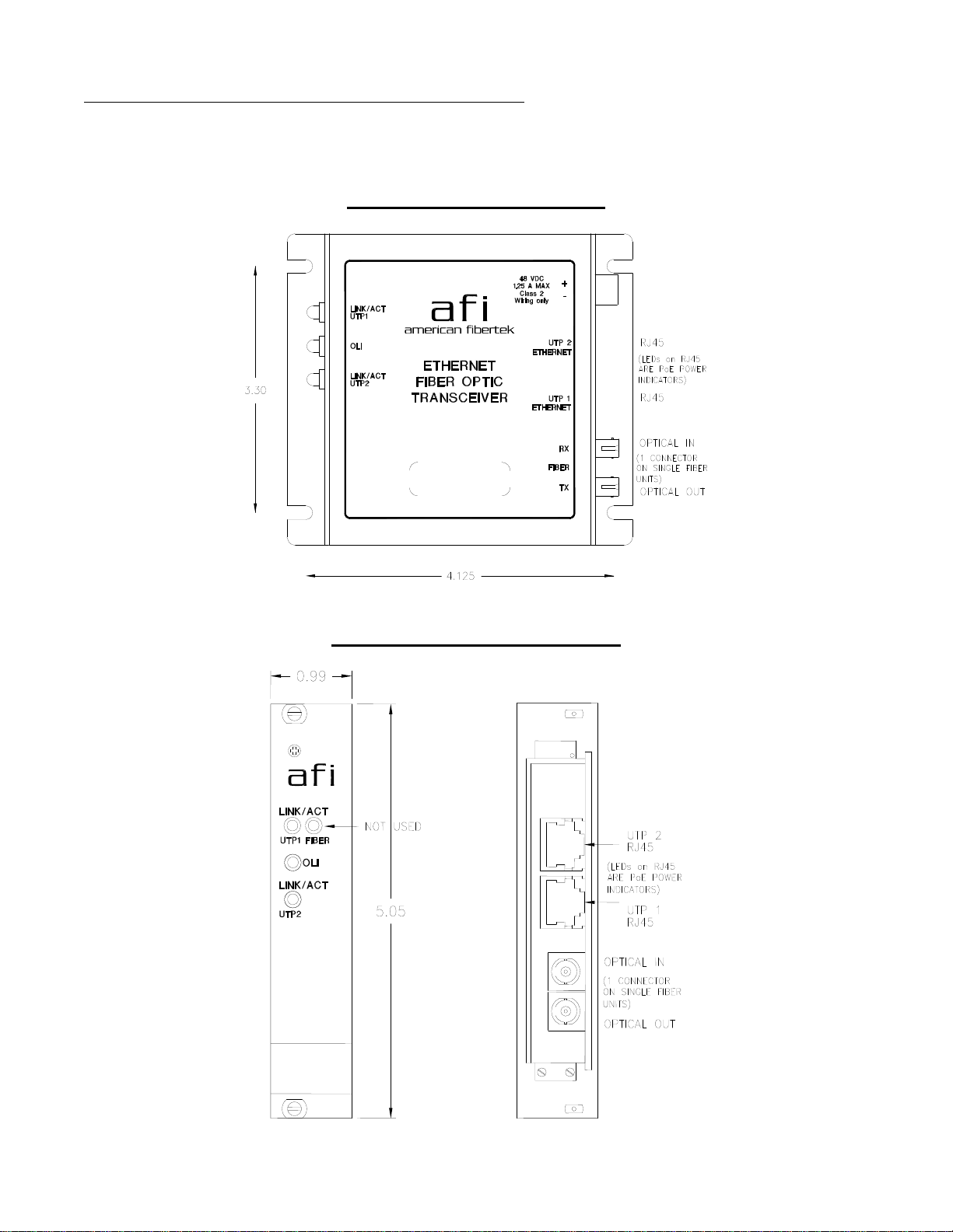
ETHERNET COPPER INPUT / OUTPUT CONNECTIONS
Two RJ-45 Ethernet ports are provided on this unit. The UTP Ethernet input/output connections are
made via RJ45 plugs. For optimum performance the shortest length of UTP wire practical should be
used.
46 PoE SERIES MODULE
46 PoE SERIES RACKCARD
4
Page 5

LED INDICATORS
UTP LINK/ACT Ethernet Data Rate Ethernet Data Status
Green 1000 BASE-T
Red 100 BASE- TX Blink – UTP Link established and Data Activity
Amber 10 BASE- T Blink – UTP Link established and Data Activity
OLI OLI Status
Green DC Power is on and optical power is at proper
RED DC Power is on but optical power is missing or at
Blink – UTP Link established and Data Activity
(will not transmit over
fiber port)
level
incorrect level
Solid – UTP Link established and No Data Activity
OFF – UTP Link is not established
Solid – UTP Link established and No Data Activity
OFF – UTP Link is not established
Solid – UTP Link established and No Data Activity
OFF – UTP Link is not established
LED INDICATORS ON THE RJ-45 CONNECTORS
PoE PoE Indication
RED PoE power is being supplied to the PD equipment
OFF No PoE power is being supplied to the PD equipment
5
Page 6
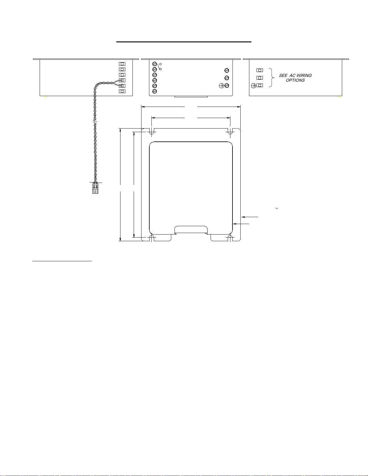
PoE POWER SUPPLY ASSEMBLY
FRONT VIEWSIDE VIEW SIDE VIEW
DC CABLE (18")
99-01-0439-50
BLACK WHITE
CONNECT TO 48Vdc
ON MODULE
WHITE
BLACK
DC OK
+V -V
+V +V -V -V
4.172
3.298
4.4304.730
TOP VIEW
LN
LN
92-06-0439
PS-48V-60W
AC Wiring Options
AFI provides linecords with plugs compatible with the NA, UK, and Euro standards
MOUNTING PLATE
POWER SUPPLY
6
Page 7

LIFETIME WARRANTY INFORMATION
American Fibertek, Inc warrants that at the time of delivery the products delivered will be free of defects
in materials and workmanship. Defective products will be repaired or replaced at the exclusive option of
American Fibertek. A Return Material Authorization (RMA) number is required to send the products
back in case of return. All returns must be shipped prepaid. This warranty is void if the products have
been tampered with. This warranty shall be construed in accordance with New Jersey law and the
courts of New Jersey shall have exclusive jurisdiction over this contract. EXCEPT FOR THE
FOREGOING WARRANTY, THERE IS NO WARRANTY OF MERCHANTABILITY OR FITNESS FOR
A PARTICULAR PURPOSE OR OTHERWISE, EXPRESSED OR IMPLIED, WHICH EXTENDS
BEYOND THE WARRANTY SET FORTH IN THIS AGREEMENT. In any event, American Fibertek will
not be responsible or liable for contingent, consequential, or incidental damages. No agreement or
understanding, expressed or implied, except as set forth in this warranty, will be binding upon American
Fibertek unless in writing, signed by a duly authorized officer of American Fibertek.
SERVICE INFORMATION
There are no user serviceable parts inside the unit.
In the event that service is required to this unit, please direct all inquiries to:
American Fibertek, Inc. Phone: (877) 234-7200
120 Belmont Drive Phone: (732) 302-0660
Somerset, NJ 08873 FAX (732) 302-0667
E-mail: [email protected]
7
 Loading...