

Page 1
© Copyright 2009, American Fibertek, Inc. 0604JD
Instruction Manual
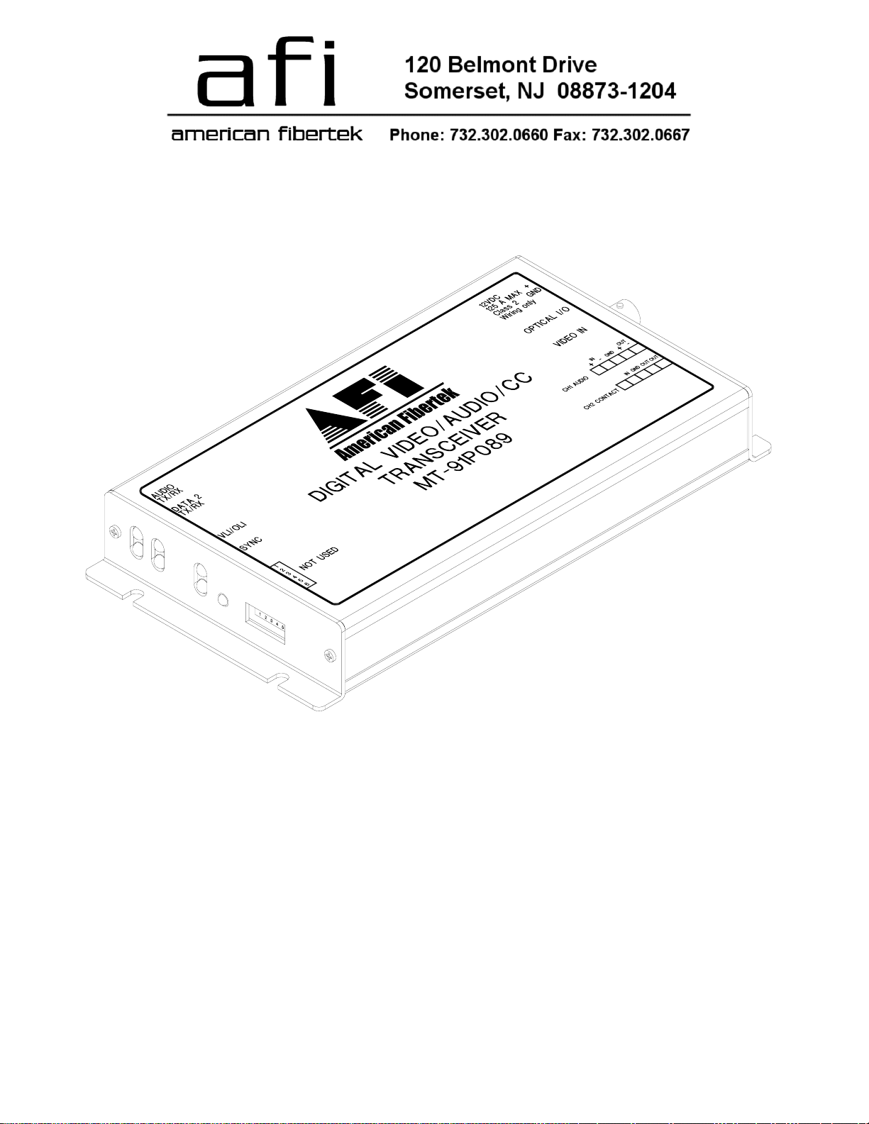
Video Transmitter With
Bi-directional Audio
And Contact Closure
MT-91P089
Page 2
INSTALLATION AND OPERATION INSTRUCTIONS
INTRODUCTION
Thank you for purchasing your American Fibertek MT-91P089 multimode video transmitter with bidirectional audio and bi-directional contact closure. Please take a few minutes to read these installation
instructions in order to obtain the maximum performance from this product.
FUNCTIONAL DESCRIPTION
The MT-91P089 operates as half of a transmitter / receiver pair for the transmission of high
performance 10 bit digital NTSC, PAL, RS170, or RS343 video signals. The MT-91P089 also supports
one bi-directional channel of four wire audio and one bi-directional channel of contact closure. The MT91P089 is designed to operate with the MR-91P089 or RR-91P089 video receiver over one multimode
fiber optic cable.
The MT-91P089 multiplexes a single video input signal along with one audio signal and one contact
closure signal into a high speed serial data stream. This serial data stream modulates a laser at 1310
nm wavelength. The MT-91P089 also detects and demultiplexes a return optical serial data stream
signal containing one audio signal and one contact closure signal at 1550 nm wavelength. The 91P089
Series product is designed to operate over an optical loss budget range of 0 to 12 dB with a maximum
distance of 4Km. Refer to the data sheet for detailed performance specifications.
This unit is contained in a rugged aluminum housing with internal dc voltage regulation. The detachable
terminal blocks and LED indicators provide for easy installation and monitoring of video, audio, contact
closure, and optical power. The MT-91P089 is designed for mounting as a modular stand alone unit.
For a rack mounted version please see the RT-91P089.
INSTALLATION
THIS INSTALLATION SHOULD BE MADE BY A QUALIFIED SERVICE PERSON AND SHOULD
CONFORM TO THE NATIONAL ELECTRICAL CODE, ANSI/NFPA 70 AND LOCAL CODES.
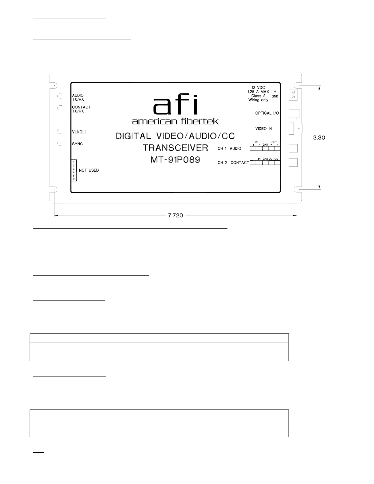
Mount the unit to a secure surface using #8 (3mm) hardware in four places. See the drawing on the
next page for mounting dimensions. Be sure to allow sufficient room for the required minimum bend
radius of the fiber cable used.
POWER SOURCE
THIS PRODUCT SHALL BE POWERED BY A LISTED CLASS 2 POWER SUPPLY ONLY.
This unit requires a +12VDC power source with a current rating of 1.25 amps for proper operation. The
DC input is diode protected. In the USA and in Canada an American Fibertek PS-12D is supplied with
this unit. The negative side of the power input is directly connected to ground. ANSI/NFPA 70 Class 2
wiring is recommended.
POWER CONNECTION
Power is supplied to the unit via a two pin terminal connector on the right side of the unit. Follow the
label on unit for proper orientation of +12 volt dc and ground.
2
Page 3
FIBER CONNECTION
The fiber optic connection is made via a ST connector located on the right side of the unit.
VIDEO INPUT CONNECTION
The video input connection is made via a BNC connector on the right side of the unit. The video input
should be connected to an appropriate 75Ω baseband video source such as a camera or a video
recorder output. For optimum performance the video cables should be the shortest length of coax
practical.
AUDIO AND CONTACT INPUT / OUTPUT CONNECTIONS
Audio and contact closure input and output connections are made via a terminal block on the right side
of the unit. Follow the label on unit for proper orientation of input and output connections. Please note
that the far right pin on the label (OUT-) corresponds with the terminal block pin located closest to the
base of the unit.
MT-91P089 STATUS INDICATORS
The MT-91P089 transmitter provides the following LED status indicators to aid in installation and
troubleshooting:
AUDIO/CONTACT TX
A green LED indicator is provided to monitor the audio / contact closure coming in from the electrical
interface, through the MT-91P089, and out onto the fiber. The intensity of this indicator will vary with
input audio levels, however in typical applications it will cycle on and off as audio is transmitted. Audio /
contact closure transmission status associated with this LED is summarized below.
AUDIO/CONTACT TX LED Audio/Contact Closure Status
Green Audio Present at Proper Signal Level/Contact Closed
Off Audio Signal Not Detected/Contact Open
AUDIO/CONTACT RX
A green LED indicator is provided to monitor the audio / contact closure coming in from the fiber,
through the MT-91P089, and out onto the electrical interface. The intensity of this indicator will vary
with input audio levels, however in typical applications it will cycle on and off as audio is received.
Audio / contact closure received status associated with this LED is summarized below.
AUDIO/CONTACT RX LED Audio/Contact Closure Status
Green Audio Present at Proper Signal Level/Contact Closed
Off Audio Signal Not Detected/Contact Open
VLI
3
Page 4
A bi-color LED indicator is provided for the video input to the MT-91P089. DC power and video status
associated with this LED is summarized below.
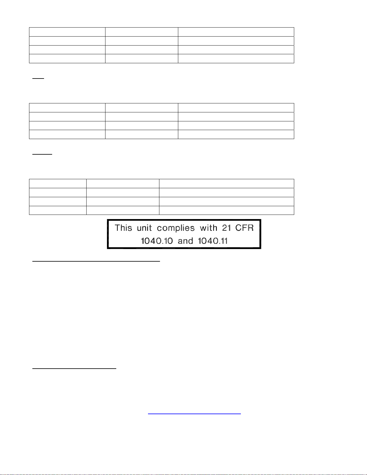
Video Presence LED DC Power Status Video Status
Green On Proper Input Video Present
Red On Input Video Not Detected
Off Off Check Power Supply
OLI
A bi-color LED indicator monitors the optical input power of the data signal that is being received at the
MT-91P089 from the MR-91P089 or the RR-91P089. DC power and optical input status associated with
this LED are summarized below.
Optical Level Indicator DC Power Status Optical Status
Green On Proper Optical Input Power Present
Red On Optical Input Not Detected
Off Off Check Power Supply
SYNC
A bi-color LED indicator is provided to monitor the proper serialization of the electrical data stream
through the MT-91P089 and out onto the fiber. DC power and sync status associated with this LED are
summarized below.
Sync LED DC Power Status Sync Status
Green On Proper Data Stream Serialization Present
Red On Data Stream Serialization Not Detected
Off Off Check Power Supply
LIFETIME WARRANTY INFORMATION
American Fibertek, Inc warrants that at the time of delivery the products delivered will be free of defects
in materials and workmanship. Defective products will be repaired or replaced at the exclusive option of
American Fibertek. A Return Material Authorization (RMA) number is required to send the products
back in case of return. All returns must be shipped prepaid. This warranty is void if the products have
been tampered with. This warranty shall be construed in accordance with New Jersey law and the
courts of New Jersey shall have exclusive jurisdiction over this contract. EXCEPT FOR THE
FOREGOING WARRANTY, THERE IS NO WARRANTY OF MERCHANTABILITY OR FITNESS FOR
A PARTICULAR PURPOSE OR OTHERWISE, EXPRESSED OR IMPLIED, WHICH EXTENDS
BEYOND THE WARRANTY SET FORTH IN THIS AGREEMENT. In any event, American Fibertek will
not be responsible or liable for contingent, consequential, or incidental damages. No agreement or
understanding, expressed or implied, except as set forth in this warranty, will be binding upon American
Fibertek unless in writing, signed by a duly authorized officer of American Fibertek.
SERVICE INFORMATION
There are no user serviceable parts inside the unit.
In the event that service is required to this unit, please direct all inquiries to:
American Fibertek, Inc. Phone: (877) 234-7200
120 Belmont Drive Phone: (732) 302-0660
Somerset, NJ 08873 FAX (732) 302-0667
E-mail: techinfo@americanfibertek.com
4
 Loading...