

American Fibertek MRX-986-UTP-SL User Manual
© Copyright 2009, American Fibertek, Inc. 0205JD
Eight Channel Video Multiplexer
With One Bi-directional Multi-Protocol
Data Channel and One Bi-directional
Instruction Manual
MTX-986-UTP-SL
MRX-986-UTP-SL
Contact Channel

Table of Contents
Functional Description ........................................................................3
Installation...........................................................................................4
Power Source / Connection ................................................................4
Fiber Connection .................................................................................4
Video, Data, and Contact Input / Output Connections........................5
Data Mode Switches...........................................................................6
Data Termination / Bias Switches.......................................................6
Data Termination Requirements.........................................................7
Offset Bias - RS485 Data Signals.......................................................7
MTX-986-UTP-SL Video Input Adjustments .......................................8
MRX-986-UTP-SL Video Output Adjustments....................................8
MTX-986-UTP-SL Status LED Indicators............................................9
MRX-986-UTP-SL Status LED Indicators.........................................10
Warranty / Service Information .........................................................12
2

INSTALLATION AND OPERATION INSTRUCTIONS
INTRODUCTION
Thank you for purchasing your American Fibertek Series 986-UTP-SL singlemode eight channel
video multiplexer with bi-directional multi-protocol data and contact closure. Please take a few
minutes to read these installation instructions in order to obtain the maximum performance from
this product.
FUNCTIONAL DESCRIPTION
The 986-UTP-SL Series units operate as a transmitter / receiver pair for the digital transmission
of eight simultaneous NTSC or PAL video signals along with one channel of field configurable
bi-directional data and one channel of bi-directional contact closure over one singlemode fiber
optic cable. The data channel may be configured as RS485 data, RS422 data, RS232 data, or
Manchester data. The RS485 channel may be configured for 2-wire (half duplex) or 4-wire (full
duplex) with or without biasing. Switch selectable internal 120 ohm terminations are available for
RS422 or RS485 data and RS485 biasing.
NOTE: This unit is shipped with Data Channel 1 in the RS422 configuration. For other
configurations, please refer to the DATA CONFIGURATION section for changes to the
default switch settings.
NOTE: This unit is shipped with data terminations off and data bias off for Data Channel
1. For other configurations, please refer to the DATA TERMINATION / BIAS section for
changes to the default switch settings.
The MTX-986-UTP-SL transmitter accepts up to eight video inputs and multiplexes these inputs
into a high speed serial data stream. This serial data stream, along with the forward data and
contact closure channels, modulates a laser at 1310nm wavelength. A Wave Division
Multiplexer combines this wavelength, along with the return data wavelength of 1550nm, onto a
single optical output port for connection to the fiber transmission system. Correspondingly, the
MRX-986-UTP-SL receiver converts the optical signal to eight independent video output signals
with the forward data and contact closure channels while transmitting the return data and
contact closure channels. The 986-UTP-SL Series product is designed to operate over an
optical loss budget range of 15dB on singlemode fiber. Refer to the product specification sheet
for additional performance data.
The 986-UTP-SL Series units are designed to be used with a UTP video interface connector.
Output video level adjustments are available to properly match a range of UTP camera devices
with this unit.
The individual units may be configured for rack mounting or wall mounting depending upon the
position of the included mounting hardware. Nominal dimensions of the MTX-986-UTP-SL and
MRX-986-UTP-SL are 1 ¾ inches high by 17 inches wide by 12 inches deep. When mounting
hardware is included, overall width increases to 19 inches wide.
3
INSTALLATION
THIS INSTALLATION SHOULD BE MADE BY A QUALIFIED SERVICE PERSON AND
SHOULD CONFORM TO THE NATIONAL ELECTRICAL CODE, ANSI/NFPA 70 AND LOCAL
CODES.
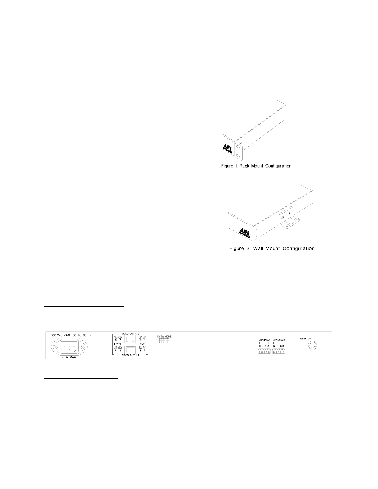
To install the MTX-986-UTP-SL or MRX-986-UTP-SL it is first necessary to mount the rack
flanges to the unit.
For rack mounting the ears are installed on the
sides of the unit with the surfaces that have
oval holes flush with the front of the unit as in
Figure 1. Mount the ears with the #10 flathead
screws provided. To mount in the rack cabinet,
use mounting screws that are appropriate for
the rack cabinet being used. When mounting
the MTX-986-UTP-SL or MRX-986-UTP-SL in
a rack configuration, it is recommended that
sufficient airflow is available through the unit.
This can be achieved by leaving a 1RU slot
above the unit open for air movement and by
leaving open space along the sides of the unit.
For mounting the unit flush to a wall or other
rigid surface, the ears may be installed on the
sides with the oval holes flush with the bottom of
the unit as in Figure 2. Mount the ears with the
#10 flathead screws provided. Mount the unit to
a rigid surface using #10 (5mm) screws.
POWER SOURCE
The internal power supply accepts universal line voltage. Any mains supply from 100 to 240
VAC, 50 to 60 Hz, may be used without modification or adjustment. A universal power
connector is provided on the rear of the unit to facilitate connection to the power mains.
POWER CONNECTION
The unit is supplied (in the US and UK only) with a three conductor power cord. The “ground”
conductor is directly connected to the chassis.
FIBER CONNECTION
The fiber optic connection is made via a FC connector located at the back of the unit. Be sure to
allow sufficient room for the required minimum bend radius of the fiber cable used.
4
 Loading...