

American Fibertek MRX-8889C User Manual
© Copyright 2005, American Fibertek, Inc. 1220JD
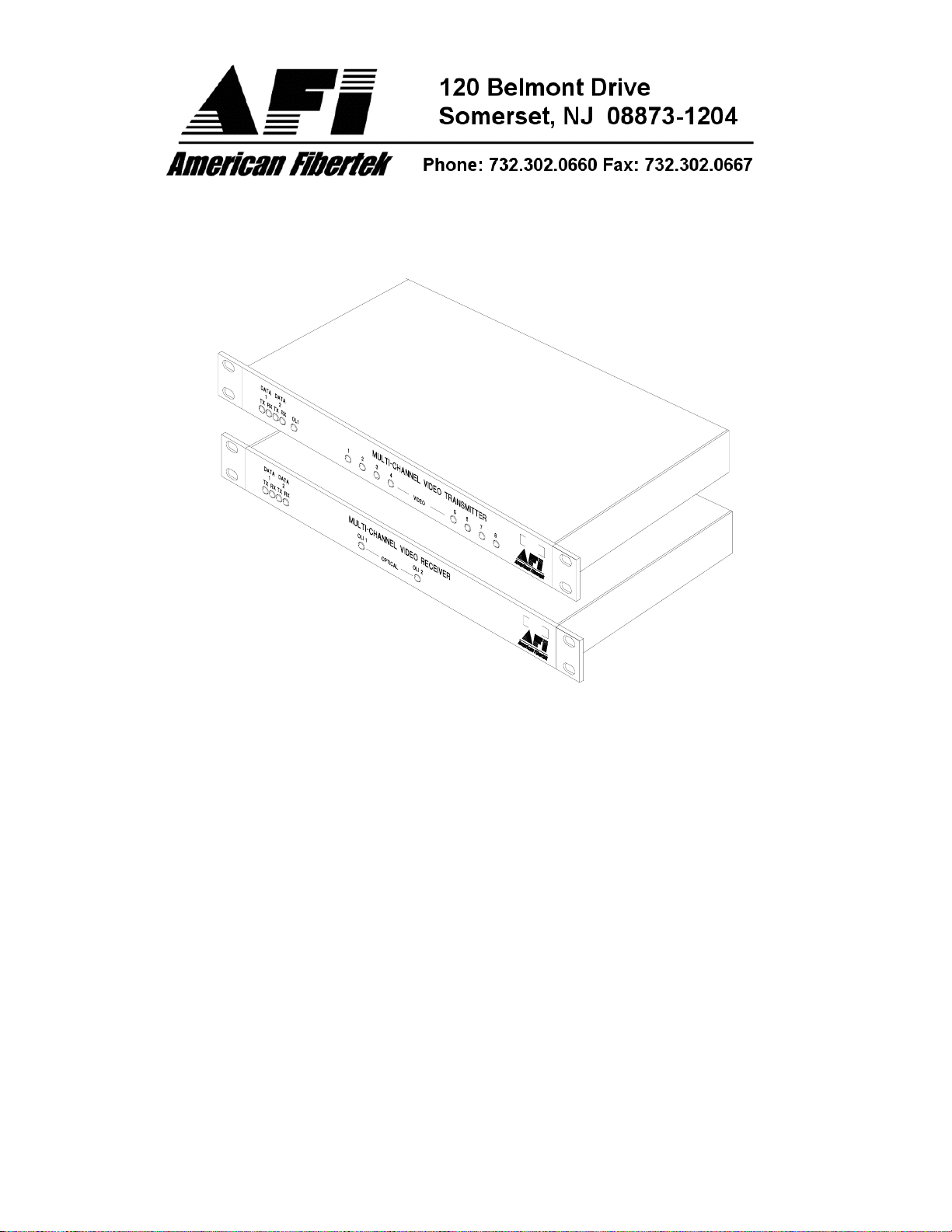
Eight Channel Video Multiplexer
Instruction Manual
with Bi-directional Data
MTX-8889C
MRX-8889C

Table of Contents
Functional Description ........................................................................3
Installation...........................................................................................3
Power Source .....................................................................................4
Power Connection...............................................................................4
Input / Output Connections .................................................................4
Typical System Data Connections......................................................5
Data Configuration Switches...............................................................6
MTX-8889C Status LED Indicators.....................................................8
MRX-8889C Status LED Indicators.....................................................9
Data Termination Requirements.......................................................10
Offset Bias - RS485 Data Signals.....................................................11
Warranty / Service Information .........................................................12
2
INSTALLATION AND OPERATION INSTRUCTIONS
INTRODUCTION
Thank you for purchasing your American Fibertek 8889C Series multimode eight channel video
multiplexer with bi-directional data. Please take a few minutes to read these installation
instructions in order to obtain the maximum performance from this product.
FUNCTIONAL DESCRIPTION
The 8889C Series units operate as a transmitter / receiver pair for the transmission of eight
simultaneous, real time baseband NTSC/PAL video signals with field configurable bi-directional
data over one multimode fiber optic cable.
This link can accommodate either a single RS485 interface (2 or 4 wire) or both an RS422
interface and a contact closure interface. When used in RS422 /Contact Closure mode, each
interface functions independent of the other. These units are factory shipped configured in
the RS422 / Contact Closure configuration.
The MTX-8889C transmitter accepts up to eight video inputs and multiplexes these signals
along with the data signals onto a single optical output port for connection to the fiber
transmission system. Correspondingly, the MRX-8889C receiver converts the optical signal to
eight independent video output signals along with the data signals.
The 8889C Series units operate on 50 um or 62.5 um multimode fiber. Refer to the data sheets
for detailed performance specifications.
The individual units may be configured for rack mounting or wall mounting depending upon the
position of the included mounting hardware.
INSTALLATION
THIS INSTALLATION SHOULD BE MADE BY A QUALIFIED SERVICE PERSON AND
SHOULD CONFORM TO THE NATIONAL ELECTRICAL CODE, ANSI/NFPA 70 AND LOCAL
CODES.
To install the MTX-8889C or MRX-8889C it is first necessary to mount the rack flanges to the
unit.
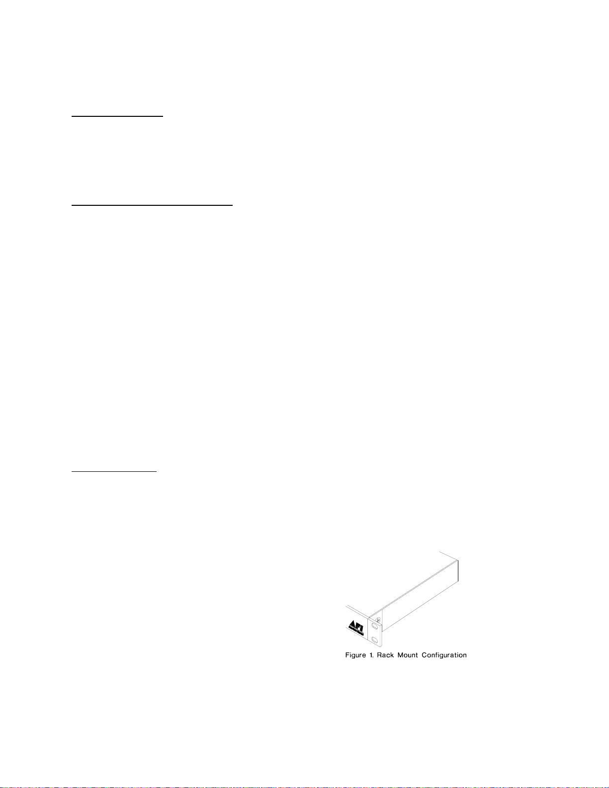
For rack mounting the ears are installed on the
sides of the unit with the surfaces that have
oval holes flush with the front of the unit as in
Figure 1. Mount the ears with the #10 flathead
screws provided. To mount in the rack cabinet,
use mounting screws that are appropriate for
the rack cabinet being used.
3
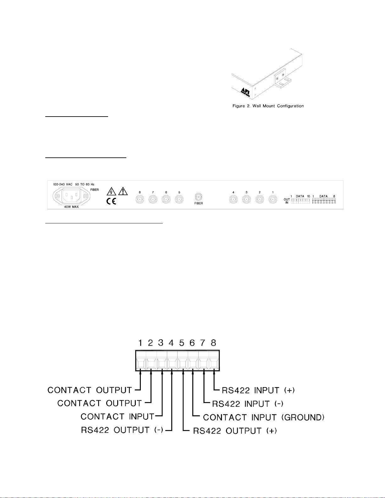
For mounting the unit flush to a wall or other rigid
surface, the ears may be installed on the sides with
the oval holes flush with the bottom of the unit as in
Figure 2. Mount the ears with the #10 flathead
screws provided. Mount the unit to a rigid surface
using #10 (5mm) screws.
POWER SOURCE
The internal power supply accepts universal line voltage. Any mains supply from 100 to 240
VAC, 50 to 60 Hz, may be used without modification or adjustment. A universal power
connector is provided on the rear of the unit to facilitate connection to the power mains.
POWER CONNECTION
The unit is supplied (in the US and UK only) with a three conductor power cord. The “ground”
conductor is directly connected to the chassis.
INPUT / OUTPUT CONNECTIONS
The fiber optic connection is made via a ST connector located at the back of the unit. Be sure to
allow sufficient room for the required minimum bend radius of the fiber cable used.
Video input and output connections are located on the rear of the unit. A BNC connector is
provided for each channel. The video inputs are connected to an appropriate 75Ω baseband
source such as a camera or a video recorder output. The 75Ω video outputs can be looped
through typical baseband video inputs of switchers, recorders and other equipment as required.
For proper operation, the outputs must be terminated with 75Ω. For optimum performance the
video cables should be the shortest length of coax practical.
Data input and output connections are located on the rear panel terminal block. A mating plug
connector is provided. The figure below identifies the specific connections for RS422 / Contact
Closure data. See next page for RS485 data connections.
4
 Loading...