

American Fibertek MX-46-FX-ST, MTX-46-FX-ST, MTX-46-FX-SL-ST, MRX-46-FX-ST, MRX-46-FX-SL-ST User Manual
...
2012_4_1JPK
Instruction Manual
Series-46
Ethernet
Data Transceiver

INSTALLATION AND OPERATION INSTRUCTIONS
INTRODUCTION
Thank you for purchasing your American Fibertek Series 46 Series Ethernet data transceiver. Please
take a few minutes to read these installation instructions in order to obtain the maximum performance
from this product.
FUNCTIONAL DESCRIPTION
The Series 46 transmitter converts a single 10/100Base-TX Ethernet input into an optical output using a
1310 nm wavelength source and also converts an optical Ethernet input signal returning on the same
fiber into an electronic Ethernet output using an 1550 nm wavelength detector. The Series 46 receiver
converts a single Ethernet input into an optical output using a 1550 nm wavelength source and also
converts an optical Ethernet input signal returning on the same fiber into an electronic Ethernet output
using an 1310 nm wavelength detector. For 2 fiber units, each direction carries the signal on a 1310nm
wavelength.
Series 46 is configured to auto negotiate either 10Base-T or 100Base-TX Ethernet data at full or half
duplex. The Series 46 also provides an auto MDI/MDIX interface which eliminates the need to provide
crossover cables depending on the equipment that it is connected to.
The 46 Series is available in the following options (see datasheets for more detail).
- 1 fiber or 2 fiber optical connections
- The FX (100Mbs) only
- SC or ST optical connectors
- Multi-mode or Singlemode
- Modules or Rackcards
INSTALLATION
THE INSTALLATION OF THIS UNIT SHOULD BE MADE BY A QUALIFIED SERVICE PERSON(S)
AND MUST CONFORM TO ALL LOCAL CODES.
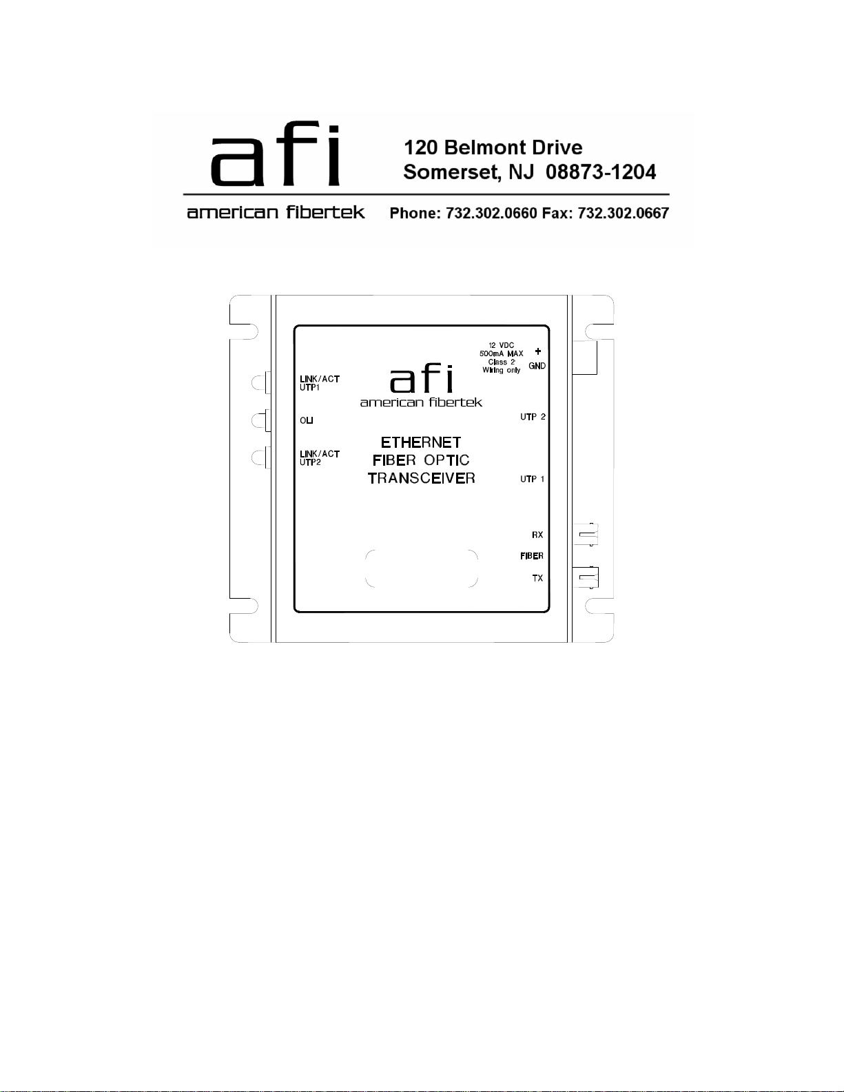
Mount the unit to a secure surface using #8 (3mm) hardware in four places. See the drawing on the
next page for mounting dimensions. Be sure to allow sufficient room for the required minimum bend
radius of the fiber cable used.
POWER SOURCE
This module unit requires a +12VDC power source for proper operation. The DC input is diode
protected. In the USA and in Canada an American Fibertek PS-12 is supplied with this unit. The
negative side of the power input is directly connected to ground. ANSI/NFPA 70 Class 2 wiring is
recommended. Power is supplied to the unit via a two pin terminal connector. Follow label on unit for
proper orientation of +12 volt dc and ground.
The rackcard is powered from a subrack. Refer to the SR-20 and PSR-2 instructions for further details.
FIBER CONNECTION
The fiber optic connection is made via an SC or ST optical connector.
ETHERNET INPUT / OUTPUT CONNECTIONS
The UTP Ethernet input/output connection is made via a RJ45 plug. For optimum performance the
shortest length of UTP wire practical should be used. Ethernet specifications permit a maximum CAT5
wire length of 100 meters.
2
 Loading...