

American Fibertek MRR-91600C-283 User Manual
12/2012 JPK
Instruction Manual
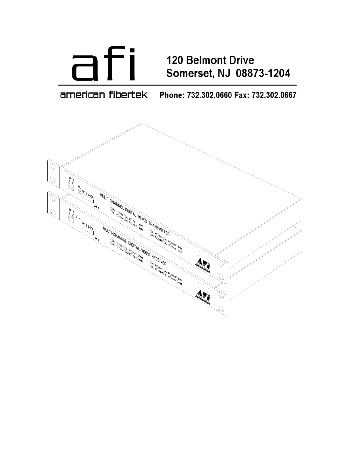
MRT-91600C-283
MRR-91600C-283
Sixteen Channel Video Multiplexer

Table of Contents
Functional Description ........................................................................3
Installation...........................................................................................3
Power Source .....................................................................................4
Fiber Connection .................................................................................4
Video Input / Output Connections.......................................................4
MRT-91600C-283 Status LED Indicators............................................5
MRR-91600C-283 Status LED Indicators...........................................6
Warranty / Service Information ...........................................................7
2
INSTALLATION AND OPERATION INSTRUCTIONS
INTRODUCTION
Thank you for purchasing your American Fibertek Series 91600C-283 multimode sixteen
channel video multiplexer. Please take a few minutes to read these installation instructions in
order to obtain the maximum performance from this product.
FUNCTIONAL DESCRIPTION
The 91600C-283 Series units operate as a transmitter / receiver pair for the digital transmission
of sixteen simultaneous NTSC or PAL video signals over one multimode fiber optic cable.
The MRT-91600C-283 transmitter accepts up to sixteen video inputs in two groups containing
eight videos and multiplexes each group into a high speed serial data stream. The first group’s
serial data stream, modulates a laser at 1310nm wavelength. The second group’s serial data
stream modulates a laser at 1550nm. A Wave Division Multiplexer (WDM) combines these two
wavelengths, onto a single optical output port for connection to the fiber transmission system.
Correspondingly, the MRR-91600C-283 receiver converts the optical signal to sixteen
independent video output signals. The 91600C-283 Series product is designed to operate over
an optical loss budget range of 0dB to 10dB on 62.5um multimode fiber over a maximum
distance of 1 Km. Refer to the product specification sheet for additional performance data.
The individual units may be configured for rack mounting or wall mounting depending upon the
installation of the included mounting hardware. Nominal dimensions of the MRT-91600C-283
and MRR-9100C are 1 ¾ inches high by 17 inches wide by 11 ½ inches deep. When mounting
hardware is included, overall width increases to 19 inches wide.
INSTALLATION
THIS INSTALLATION SHOULD BE MADE BY A QUALIFIED SERVICE PERSON AND
SHOULD CONFORM TO THE NATIONAL ELECTRICAL CODE, ANSI/NFPA 70 AND LOCAL
CODES.
To install the MRT-91600C-283 or MRR-91600C-283 it is first necessary to mount the rack
flanges to the unit.
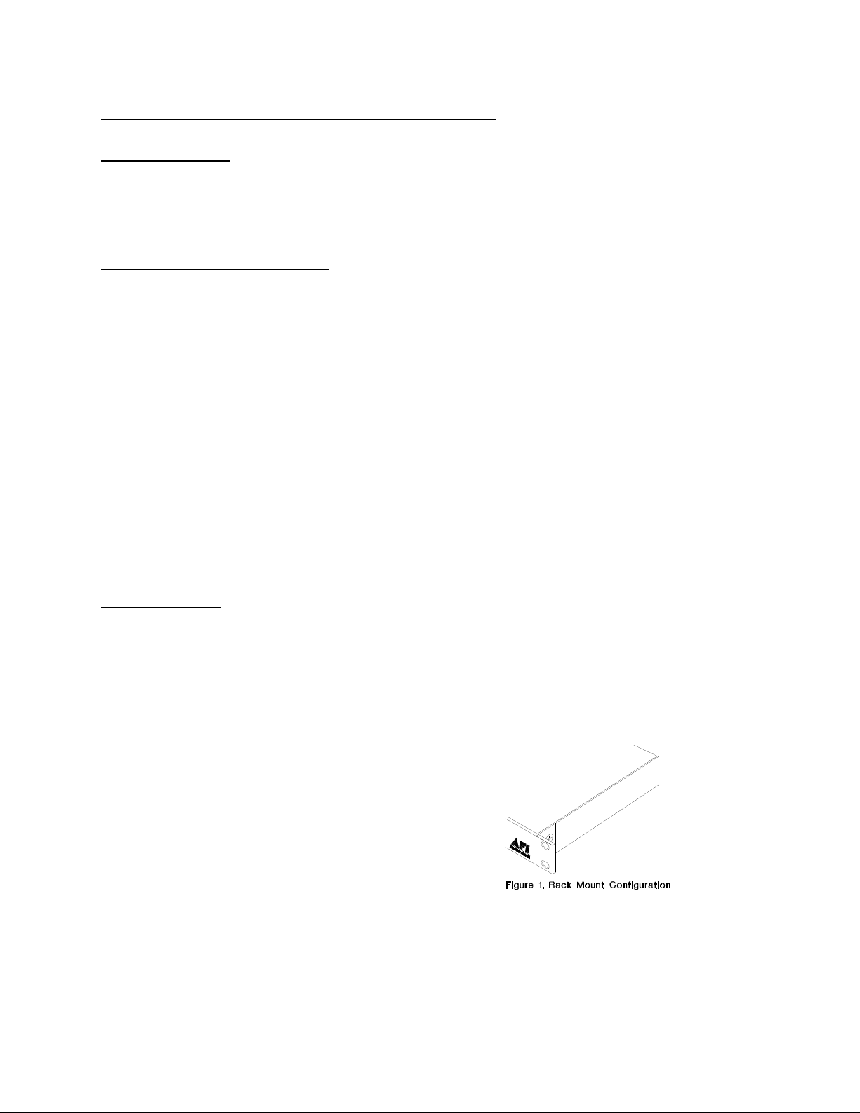
For rack mounting the ears are installed on the
sides of the unit with the surfaces that have
oval holes flush with the front of the unit as in
Figure 1. Mount the ears with the #10 flathead
screws provided. To mount in the rack cabinet,
use mounting screws that are appropriate for
the rack cabinet being used. When mounting
the MRT-91600C-283 or MRR-91600C-283 in
a rack configuration, it is recommended that
sufficient airflow is available through the unit.
This can be achieved by leaving a 1RU slot above the unit open for air movement and by
leaving open space along the sides of the unit.
3
 Loading...