

American Fibertek MRM-1485 User Manual
Instruction Manual
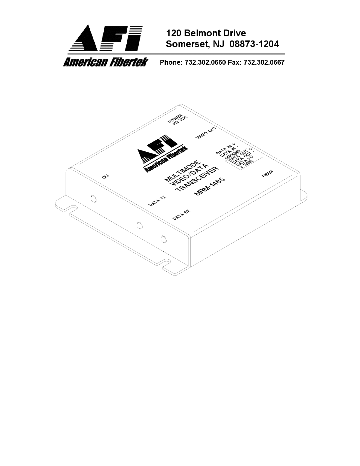
MRM-1485
Video Receiver
With Bi-directional RS485 Data
© Copyright 2005, American Fibertek, Inc. 0209JD

Table of Contents
Functional Description....................................................................... 3
Installation......................................................................................... 3
Power Source.................................................................................... 3
Power Connection............................................................................. 3
Input / Output Connections ............................................................... 4
Data Configuration ............................................................................ 4
Switch/Jumper Settings..................................................................... 5
MRM-1485 Status LED Indicators..................................................... 6
RS-485 Termination and Offset Bias Requirements.......................... 7
Warranty ........................................................................................... 8
Service Information ........................................................................... 8
2

INSTALLATION AND OPERATION INSTRUCTIONS
INTRODUCTION
Thank you for purchasing your American Fibertek MRM-1485 multimode mini video
receiver with RS485 transceiver. Please take a few minutes to read these installation
instructions in order to obtain the maximum performance from this product.
FUNCTIONAL DESCRIPTION
The MRM-1485 operates as half of a transmitter / receiver pair for the transmission of
baseband NTSC, PAL, RS170, or RS343 video signals and bi-directional RS485 data. It
is designed to operate with the MTM-1485 or RTM-1485 video transmitter with RS485
transceiver over a single multimode fiber optic cable.
The MRM-1485 converts a FM modulated optical fiber input into a single video output
and a single RS485 output using a 1300 nm wavelength detector. The MRM-1485 also
converts an electrical RS485 input signal into an optical RS485 output returning on the
same fiber using an 850 nm wavelength source. This unit may be configured for two
wire half duplex or four wire full duplex electrical interfaces. The M1485 Series product
is designed to operate over an optical loss budget range of 0 to 12 dB. The MRM-1485
operates on 50 um or 62.5 um multimode fiber. Refer to the data sheets for detailed
performance specifications.
This unit is contained in a compact and rugged aluminum housing with internal dc
voltage regulation. The detachable terminal block and LED indicators provide for easy
installation and monitoring of video, data, and dc power.
The MRM-1485 is designed for mounting as a modular stand alone unit. For a rack
mounted version please see the RRM-1485.
INSTALLATION
THE INSTALLATION OF THIS UNIT SHOULD BE MADE BY A QUALIFIED SERVICE
PERSON(S) AND MUST CONFORM TO ALL LOCAL CODES.
Mount the unit to a secure surface using #8 (3mm) hardware in four places. See the
drawing on the next page for mounting dimensions. Be sure to allow sufficient room for
the required minimum bend radius of the fiber cable used.
POWER SOURCE
This unit requires a +12VDC power source for proper operation. The DC input is diode
protected. In the USA and in Canada an American Fibertek PS-12 is supplied with this
unit. The negative side of the power input is directly connected to ground. ANSI/NFPA
70 Class 2 wiring is recommended.
POWER CONNECTION
Power is supplied to the unit via a two pin terminal connector. Follow label on unit for
proper orientation of +12 volt dc and ground.
3
 Loading...