

American Fibertek MR-91P558 User Manual
© Copyright 2008, American Fibertek, Inc. 0625JD
Instruction Manual
Video Receiver With
Multi-Protocol Data
MR-91P558
Bi-directional
And Audio

Table of Contents
Functional Description..............................................................................…3
Installation ................................................................................................... 3
Power Source.............................................................................................. 3
Power Connection .......................................................................................4
Fiber Connection .........................................................................................4
Video Input Connection ...............................................................................4
Data Input / Output Connections .................................................................5
Typical System Data Connections............................................................... 5
Data Configuration....................................................................................... 5
RS485 Data Signals .................................................................................... 6
Offset Bias - RS485..................................................................................... 6
MR-91P558 Status LED Indicators.............................................................. 7
Warranty...................................................................................................... 8
Service Information...................................................................................... 8
2

INSTALLATION AND OPERATION INSTRUCTIONS
INTRODUCTION
Thank you for purchasing your American Fibertek MR-91P558 multimode video receiver with two
channels of bi-directional multi-protocol data and one channel of bi-directional audio. Please take a few
minutes to read these installation instructions in order to obtain the maximum performance from this
product.
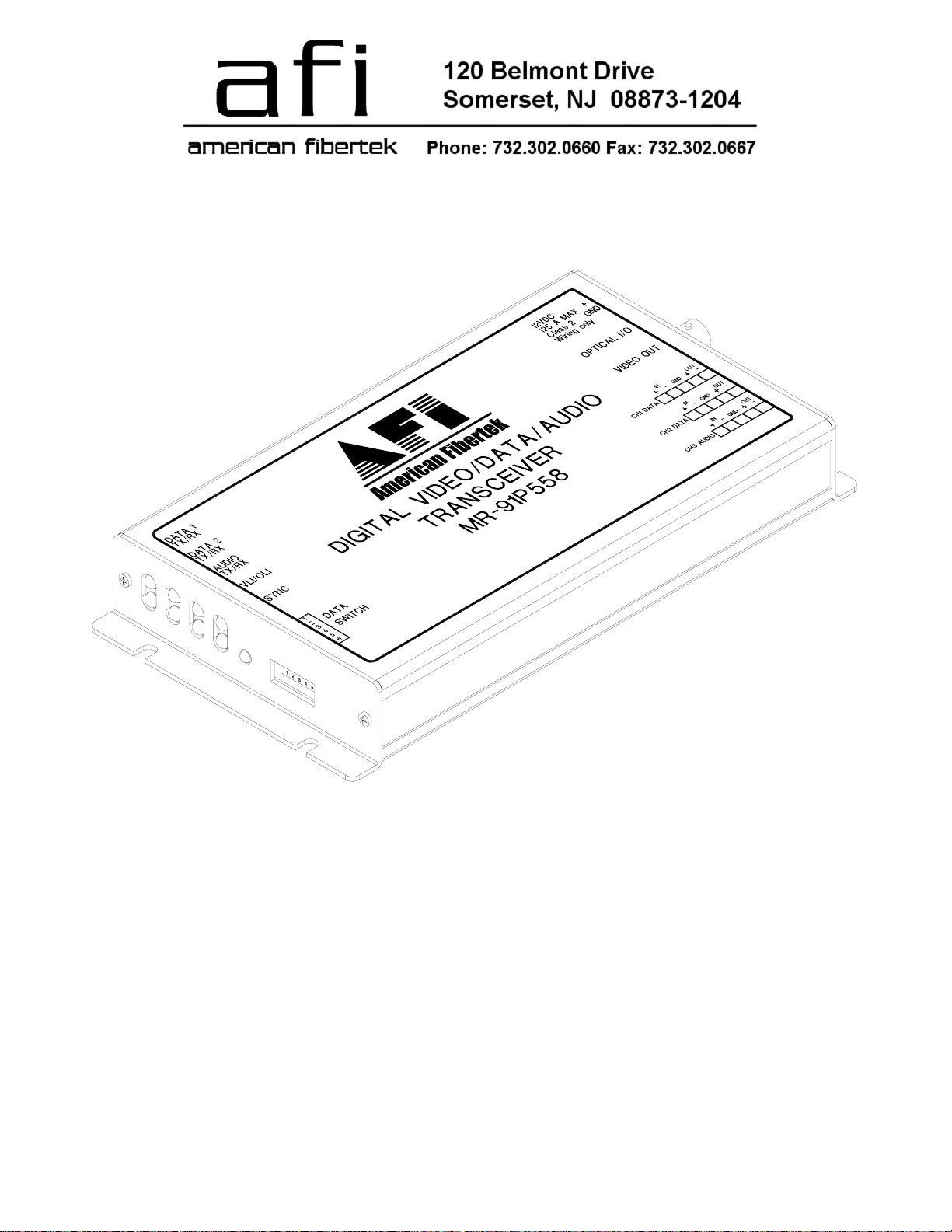
FUNCTIONAL DESCRIPTION
The MR-91P558 operates as half of a transmitter / receiver pair for the transmission of high
performance 10 bit digital NTSC, PAL, RS170, or RS343 video signals. The MR-91P558 also supports
two bi-directional channels of RS485 (2 or 4 wire), RS422, RS232 or Manchester data. A third channel
supports bi-directional four wire audio.
NOTE: This unit is shipped in the following default configuration. For other configurations,
please refer to the DATA CONFIGURATION section for changes to the default switch settings.
Channel 1: RS485 (4 wire) or Manchester data
Channel 2: RS485 (4 wire) or Manchester data
Channel 3: Audio
The MR-91P558 is designed to operate with the MT-91P558 or RT-91P558 video transmitter with bidirectional data and audio over one multimode fiber optic cable.
The MR-91P558 multiplexes two data signals and one audio signal into a high speed serial data
stream. This serial data stream modulates a laser at 1550 nm wavelength. The MR-91P558 also
detects and demultiplexes a return optical serial data stream signal containing a single video input
signal along with two data channels and one audio channel at 1310 nm wavelength. The 91P558
Series product is designed to operate over an optical loss budget range of 0 to 12 dB with a maximum
distance of 4 Km. Refer to the data sheet for detailed performance specifications.
The RS485 channel may be configured for 2-wire (half duplex) or 4-wire (full duplex) operation with or
without biasing. Switch selectable internal 120 ohm terminations are available for RS422 or RS485
data.
This unit is contained in a rugged aluminum housing with internal dc voltage regulation. The detachable
terminal blocks and LED indicators provide for easy installation and monitoring of video, data, audio,
and optical power.
The MR-91P558 is designed for mounting as a modular stand alone unit. For a rack mounted version
please see the RR-91P558.
INSTALLATION
THIS INSTALLATION SHOULD BE MADE BY A QUALIFIED SERVICE PERSON AND SHOULD
CONFORM TO THE NATIONAL ELECTRICAL CODE, ANSI/NFPA 70 AND LOCAL CODES.
Mount the unit to a secure surface using #8 (3mm) hardware in four places. See the drawing on the
next page for mounting dimensions. Be sure to allow sufficient room for the required minimum bend
radius of the fiber cable used.
POWER SOURCE
THIS PRODUCT SHALL BE POWERED BY A LISTED CLASS 2 POWER SUPPLY ONLY.
This unit requires a +12VDC power source with a current rating of 1.25 amps for proper operation. The
DC input is diode protected. In the USA and in Canada an American Fibertek PS-12D is supplied
3
 Loading...