

American Fibertek MR-88 User Manual
© Copyright 2008, American Fibertek, Inc. 0609JD
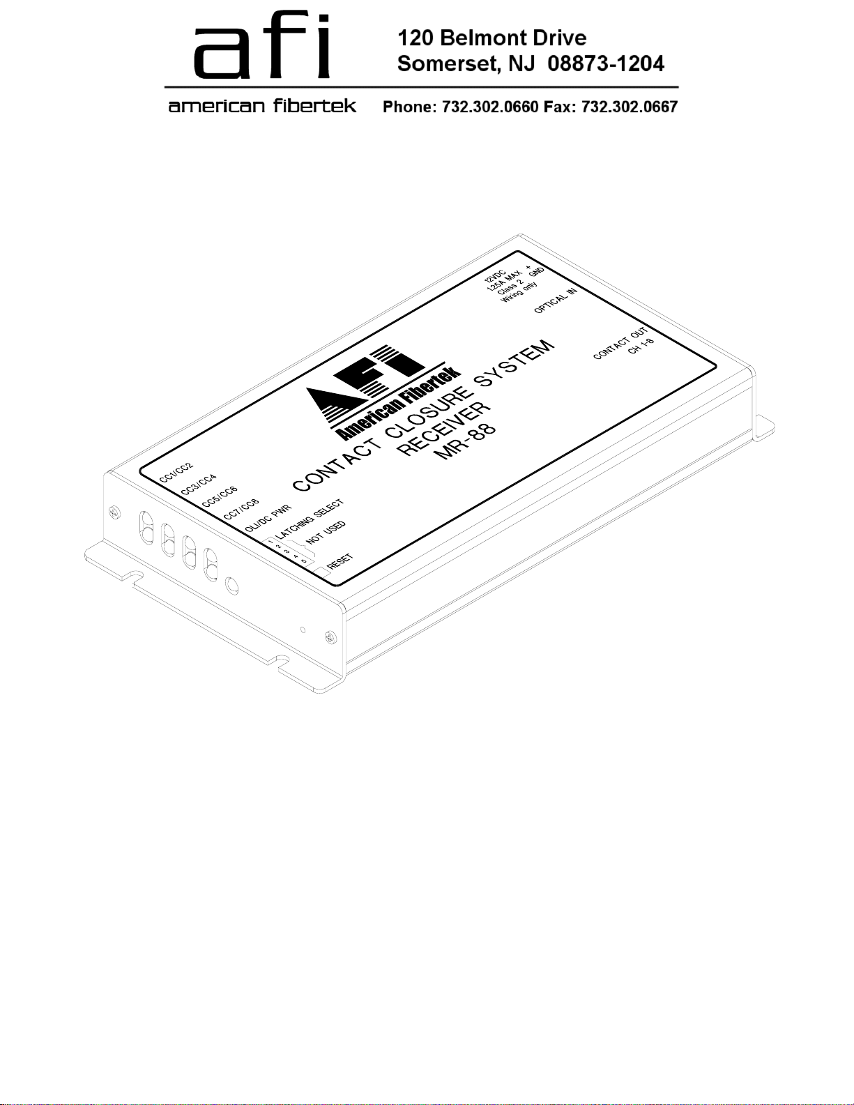
Contact Closure Receiver
Instruction Manual
MR-88
Eight Channel
INSTALLATION AND OPERATION INSTRUCTIONS
INTRODUCTION
Thank you for purchasing your American Fibertek MR-88 multimode supervised contact receiver.
Please take a few minutes to read these installation instructions in order to obtain the maximum
performance from this product.
FUNCTIONAL DESCRIPTION
The MR-88 operates as half of a transmitter/receiver pair for the transmission of eight supervised dry
latching contact closure signals. It is designed to operate with the MT-88 or RT-88 supervised contact
transmitter over one multimode fiber optic cable. The MR-88 has a user selectable switch that allows
the contact status sent by the MT-88 or RT-88 to be maintained unchanged through loss of optical or
electrical power at the receiver. Both the transmitter and receiver include a recessed button to clear all
contacts to a default state.
The MR-88 converts an optical input into eight contact closure outputs using a 1310 nm wavelength
detector. The 88 Series product is designed to operate over an optical loss budget range of 0 to 12 dB.
The MR-88 operates on 62.5 um multimode fiber. Refer to the data sheets for detailed performance
specifications.
This unit is contained in a compact and rugged aluminum housing with internal dc voltage regulation.
The detachable terminal blocks and LED indicators provide for easy installation and monitoring of
contact closure and power.
The MR-88 is designed for mounting as a modular stand alone unit. For a rack mounted version please
see the RR-88.
INSTALLATION
THIS INSTALLATION SHOULD BE MADE BY A QUALIFIED SERVICE PERSON AND SHOULD
CONFORM TO THE NATIONAL ELECTRICAL CODE, ANSI/NFPA 70 AND LOCAL CODES.
Mount the unit to a secure surface using #8 (3mm) hardware in four places. See the drawing on the
next page for mounting dimensions. Be sure to allow sufficient room for the required minimum bend
radius of the fiber cable used.
POWER SOURCE
THIS PRODUCT SHALL BE POWERED BY A
LISTED CLASS 2 POWER SUPPLY ONLY.
This unit requires a 12 volt DC power source for
proper operation. In the USA and in Canada an
American Fibertek PS-12D is supplied with this
unit. ANSI/NFPA 70 Class 2 wiring is
recommended.
POWER CONNECTION
Power is supplied to the unit via a two pin terminal
connector on the right side of the unit. See label
on unit for proper location of input power.
FIBER INPUT CONNECTION
The optical input connection is made via a FC/PC connector located on the right side of the unit.
2
 Loading...