

American Fibertek MR-780C-SL User Manual
© Copyright 2004, American Fibertek, Inc. 1001JD
Eight Channel Video Receiver
Instruction Manual
MR-780C-SL

INSTALLATION AND OPERATION INSTRUCTIONS
INTRODUCTION
Thank you for purchasing your American Fibertek MR-780C-SL singlemode eight channel video
receiver. Please take a few minutes to read these installation instructions in order to obtain the
maximum performance from this product.
FUNCTIONAL DESCRIPTION
The MR-780C-SL operates as half of a transmitter / receiver pair for the transmission of eight
channels of high performance digital NTSC, PAL, RS170, or RS343 video signals. The MR780C-SL is designed to operate with the MT-780C-SL or RT-780C-SL video transmitter over
one singlemode fiber optic cable.
The MR-780C-SL detects and demultiplexes an optical serial data stream containing eight video
signals at 1310 nm wavelength. The 780C-SL Series product is designed to operate over an
optical loss budget range of 0 to 21 dB. Refer to the data sheets for detailed performance
specifications.
This unit is contained in a rugged aluminum housing with internal dc voltage regulation. The
detachable terminal blocks and LED indicators provide for easy installation and monitoring of
video, sync, and optical power.
The MR-780C-SL is designed for mounting as a modular stand alone unit. For a rack mounted
version please see the RR-780C-SL.
INSTALLATION
THE INSTALLATION OF THIS UNIT SHOULD BE MADE BY A QUALIFIED SERVICE
PERSON(S) AND MUST CONFORM TO ALL LOCAL CODES.
Mount the unit to a secure surface using #8 (3mm) hardware in four places. See the drawing on
the next page for mounting dimensions. Be sure to allow sufficient room for the required
minimum bend radius of the fiber cable used.
POWER SOURCE
This unit requires a +12VDC power source for proper operation. The DC input is diode
protected. In the USA and in Canada an American Fibertek PS-12D is supplied with this unit.
The negative side of the power input is directly connected to ground. ANSI/NFPA 70 Class 2
wiring is recommended.
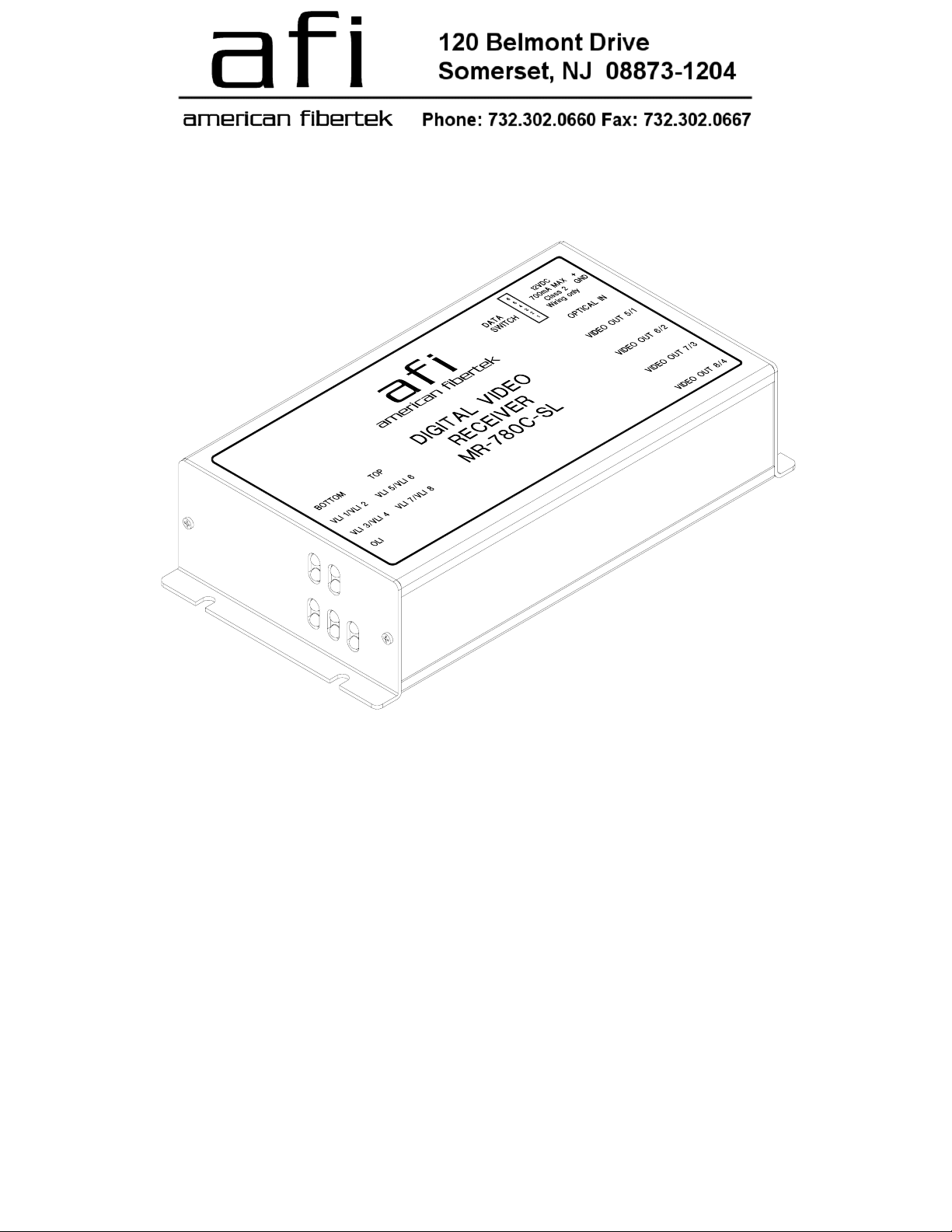
POWER CONNECTION
Power is supplied to the unit via a two pin terminal connector on the right side of the unit. Follow
the label on unit for proper orientation of +12 volt dc and ground.
FIBER CONNECTION
The fiber optic connection is made via a FC/PC connector located on the right side of the unit.
VIDEO OUTPUT CONNECTIONS
The video output connections are made via BNC connectors on the right side of the unit. The
75Ω video outputs can be looped through typical baseband video inputs of switchers, recorders
and other equipment as required. For proper operation, the outputs must be terminated with
75Ω. For optimum performance the video cables should be the shortest length of coax practical.
2
 Loading...