

American Fibertek MR-440C-SL User Manual
© Copyright 2005, American Fibertek, Inc. 0930JD
Four Channel Video Receiver
Instruction Manual
MR-440C-SL
INSTALLATION AND OPERATION INSTRUCTIONS
INTRODUCTION
Thank you for purchasing your American Fibertek MR-440C-SL singlemode four channel video
receiver. Please take a few minutes to read these installation instructions in order to obtain the
maximum performance from this product.
FUNCTIONAL DESCRIPTION
The MR-440C-SL operates as half of a transmitter / receiver pair for the transmission of four
simultaneous, real time, baseband NTSC, PAL, RS170, or RS343 video signals. The MR-440CSL is designed to operate with the MT-440C-SL or RT-440C-SL video transmitter over one
singlemode fiber optic cable.
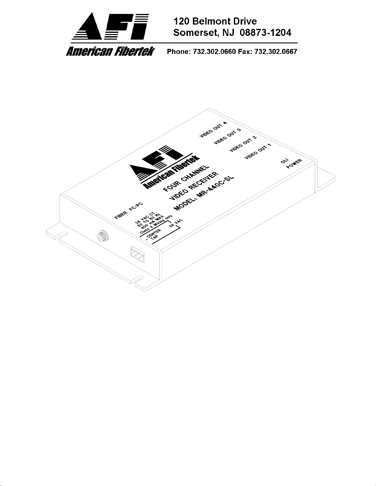
The MR-440C-SL receiver converts a single optical input into a maximum of four video outputs.
The 440C-SL Series product is designed to operate over an optical loss budget range of 0 to 12
dB when used on 9 um singlemode fiber. Refer to the product specification sheet for additional
performance data.
This unit is contained in a compact and rugged extruded aluminum housing with internal dc
voltage regulation. The detachable terminal block and LED indicators provide for easy
installation and monitoring of video and power.
The MR-440C-SL is designed for mounting as a modular stand alone unit. For a rack mounted
version please see the RR-440C-SL.
INSTALLATION
THIS INSTALLATION SHOULD BE MADE BY A QUALIFIED SERVICE PERSON AND
SHOULD CONFORM TO THE NATIONAL ELECTRICAL CODE, ANSI/NFPA 70 AND LOCAL
CODES.
Mount the unit to a secure surface using #8 (3mm) hardware in four places. See the drawing on
the next page for mounting dimensions. Be sure to allow sufficient room for the required
minimum bend radius of the fiber cable used.
2
 Loading...