

Page 1

IET8242MPpH-S-DR
Hardened Managed 8-port 10/100/1000Base-TX(PoE+) + 4 port 100/1000Base-FX SFP
Ethernet Switch
1. Introduction
This installation manual describes the installation procedures of the Hardened Managed 8-port
10/100/1000Base-TX(PoE+) + 4-port 100/1000Base-FX SFP Ethernet Switch. This is the Switch of choice to
suit for supporting standard industrial applications. Managed switches are easily to prioritize, partition and
organize user’s network and provide reliable and good quality services
2. Environmental Aspects
This is the perfect choice to work in within a constrained space that between a harsh temperature extremes of
-40∘C and 75∘C (-40∘F and 167∘F) inclusively for the Hardened IET8242MPpH respectively. It caters for
a group of 8 ports of Gigabit Ethernet Switch.
3. Unpacking. Inspecting and storing
3.1 Removing the transport packaging
Examine the delivered product thoroughly to ensure that the product has not been damaged during
transportation. Remove the transport packing carefully without any force.
3.2 Identifying the product
Locate the order number of the delivered product from the label of the on top of the packing box and check
against the ordering information to verify that the received product is correct.
3.3 Check the delivery product
Check that all items are included in the delivery in accordance with the delivery documents.
3.4 Inspecting the product
Check the product carefully to see if any damage occurred during the transportation. Notify the supplier
immediately if there are any discrepancies or damage in relation to the delivery documents.
3.5 Storing
If the product is stored before installation, it must be done with the original transport packaging in a dry
and dust free environment.
3.6 Packaging content and product description
1
Page 2

IET8242MPpH-S-DR
Hardened Managed 8-port 10/100/1000Base-TX(PoE+) + 4 port 100/1000Base-FX SFP
Ethernet Switch
Package Content
1. IET8242MPpH Hardened L2+ Managed Ethernet Switch x 1
2. DIN rail brackets and screws
3. Terminal Block
4. RJ45 Ethernet Port to DB9 Serial Console cable
5. Quick Installation Guide x 1
4. Mounting & Installation
a) DIN-Rail Mounting
1. Attach the DIN rail mounting kit to rear panel of the chassis. Insert screws and tighten then with a
screwdriver to secure the kit.
Attaching DIN Rail kit to the Switch
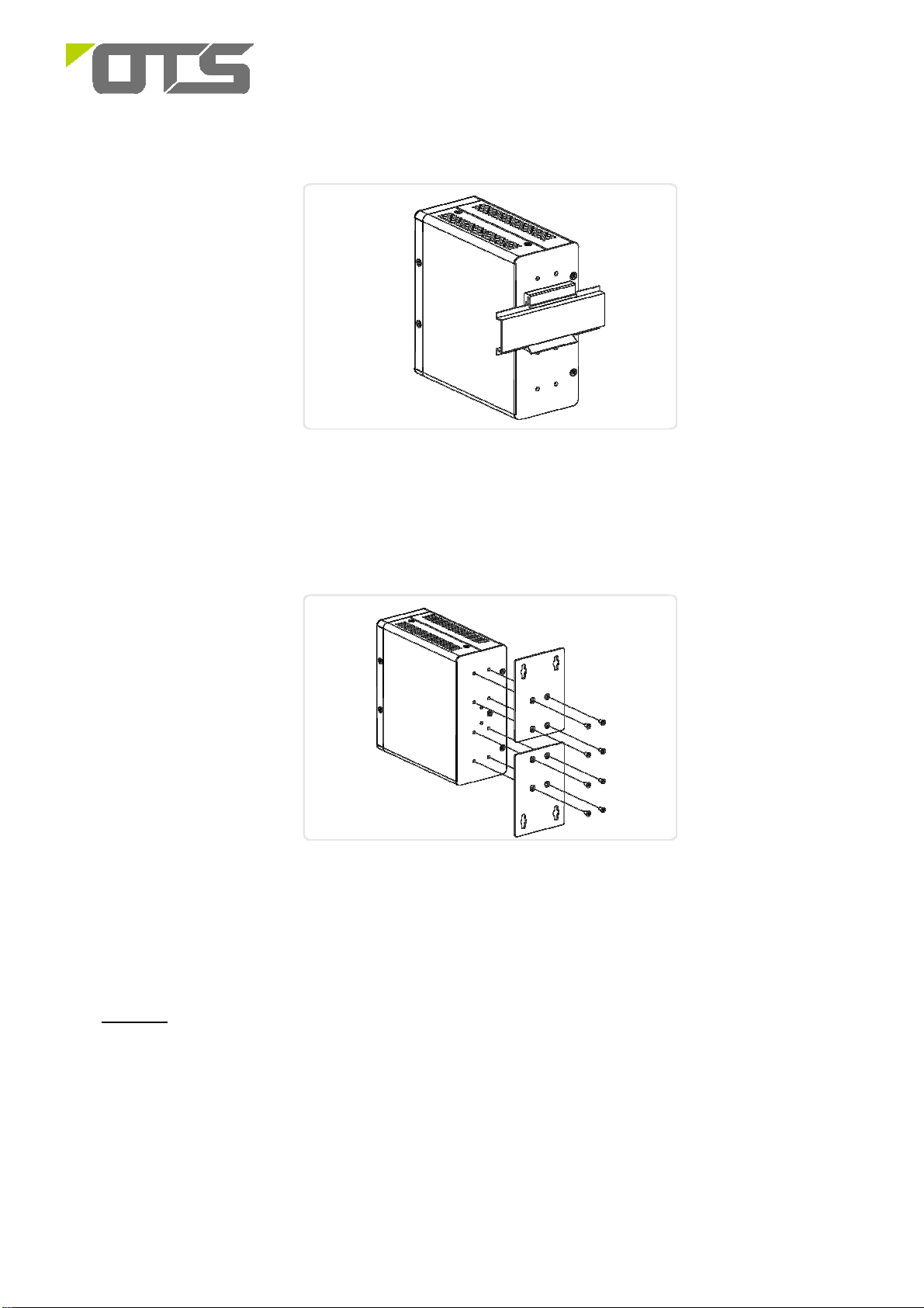
2. Insert the upper lip of the DIN rail into the DIN-rail mounting kit. And press the switch towards the
DIN rail until it snaps into place.
Insert switch to the DIN rail
3. Make sure that the switch is attached securely to DIN rail.
2
Page 3
IET8242MPpH-S-DR
Hardened Managed 8-port 10/100/1000Base-TX(PoE+) + 4 port 100/1000Base-FX SFP
Ethernet Switch
The switch is attached to DIN Rail
b)
Wall Mount Installation(Optional)
1. Attach the wall mounting plates to rear panel of the chassis. Insert screws and tighten then with a
screwdriver to secure the plates.
Attaching Wall Mounting Plates to the Switch
2. Install user-supplied screws on the appropriate location on the wall.
3. Make sure that the switch is attached securely to wall.
5. Start-up
a. Connect the Ethernet port of the Hardened Managed PoE Ethernet Switch to a PC or network device with a
network cable.
b. Insert the appropriate SFP module into the SFP port. Connect the fiber cable from the remote device to the LC
connector of the SFP of the Switch (near end).
c. After the devices are powered on, the PWR indicators will all be on. If the indicators are not on, check the
power supply connection.
d. After all cables are correctly connected, the indicators will be lit as per port status LEDs. Please refer to the
Operational Instructions for detail descriptions
3
Page 4

IET8242MPpH-S-DR
Hardened Managed 8-port 10/100/1000Base-TX(PoE+) + 4 port 100/1000Base-FX SFP
Ethernet Switch
Cable Connections
Signal Type Cable Type Connector
Ethernet Cat. 5e or above RJ45
SFP Fiber LC
Power supply Power cable Terminal Block
6. Technical Data
Power Connecting
The switch can be powered from two power supplies (input range 48V – 57V). Insert the positive and negative
wires into V+ and V- contact on the terminal block and tighten the wire-clamp screws to prevent the wires from
being loosened.
Connecting DC power cord
Note:The wire gauge for the terminal block should range between 18~20 AWG
DI/DO connecting
Connecting DI/DO Relay Wires
1. Insert the negative(ground)/positive DI/DO Relay wires into the +/- terminals, respectively.
2. To keep the DI/DO Relay wires from pulling loose, use a small flat-blade screwdriver to tighten the
wire-clamp screws on the front of the terminal block connector.
4
Page 5

IET8242MPpH-S-DR
Hardened Managed 8-port 10/100/1000Base-TX(PoE+) + 4 port 100/1000Base-FX SFP
Ethernet Switch
3. Insert the terminal block connector prongs into the terminal block receptor.
FAULT:
The two contacts of the terminal block connector are used to detect user-configured events. The two
wires attached to the fault contacts form an open circuit when a user-configured even is triggered. If
a user-configured event does not occur, the fault circuit remains closed.
Ethernet Interface Connecting (
For both 100/1000 Mbps fiber speed connections, the SFP slots are available. The SFP slot accepts the fiber
transceivers that typically have an LC connector.
The fiber transceivers have options of multimode, single mode, long-haul or special-application transceivers.
To connect the transceiver and LC cable, please follow below steps:
Step1 Insert the SFP transceiver module into the SFP slots as shown below. Notice that the
triangle mark is at the bottom of the SFP slot.
Fiber, SFP
)
Transceiver to the SFP Module Transceiver Inserted
Step2 Insert the fiber cable of the LC connector into the transceiver as shown below.
LC connector to the Transceiver
5
Page 6

IET8242MPpH-S-DR
Hardened Managed 8-port 10/100/1000Base-TX(PoE+) + 4 port 100/1000Base-FX SFP
Ethernet Switch
Reset Button
By pressing the Reset button for certain period of time, users can perform the following tasks.
• Reset the switch
To reboot and get the switch back to the previous configuration setting saved.
• Restore the switch to Factory defaults
To restore the original factory default setting back to the switch.
Time Period of
SYS LED
Task to be Performed
Pressing Button
Behavior
Blinking
Reset the Switch 2 ~ 7 seconds
Green
Blinking
Restore to Defaults 7 ~ 12 seconds
Green
Connect & Login to IET8242MPpH-S-DR Switch
1. Connecting PC to IET8242MPpH-S-DR Ethernet port (RJ45 Ethernet port).
2.
Factory default IP: 192.168.2.1
3. Login with default account and password.
Username: admin
Password: system
LED Indicators:
Port Status LED
Behavior
ALL LEDs Light OFF
ALL LEDs Stay ON
Table 1 : Power LEDs
LED Color State Description
Power1 Green
Power2 Green
On The switch is powered ON correctly.
Off The switch is not receiving power from power1.
On The switch is powered ON correctly.
Off The switch is not receiving power from power2.
Table 2 : System LED
LED Color State Description
System Green
On The switch is ready.
Off The switch is not ready.
Table 3 : Alarm LED
6
Page 7

established a link to connected device. Otherwise, the port may have
atus, has been detected in the
established a link to connected device. Otherwise, the port may have
IET8242MPpH-S-DR
Hardened Managed 8-port 10/100/1000Base-TX(PoE+) + 4 port 100/1000Base-FX SFP
Ethernet Switch
LED Color State Description
On
Alarm Red
Off The system is normal.
An abnormal state, such as temperature, voltage or
DC power1/2, has been detected in the switch.
Table 4: Port Status LEDs
LED Color
Green
Green Blinking
RJ45
Amber
Ports
UP
Amber Blinking
-- Off
State Description
The port is enabled and established a link to connected device, and
On
the connection speed is 1000Mbps.
The port is transmitting/receiving packets, and the connection speed
is 1000Mbps.
The port is enabled and established a link to connected device, and
On
the connection speed is 10/100Mbps.
The port is transmitting/receiving packets, and the connection speed
is 10/100Mbps.
The port has no active network cable connected, or it is not
RJ45
Ports
Down
SFP
Ports
Green
Amber
-- Off
Green
Green Blinking
Amber
Amber Blinking
On The port is enabled and supplying power to connected device.
On
On
On
been disabled through the switch user interface.
An abnormal state, such as overload st
switch.
The port has no active network cable connected, or it is not
connected a PoE PD device. Otherwise, the port may have been
disabled through the switch user interface.
The port is enabled and established a link to connected device, and
the connection speed is 1000Mbps.
The port is transmitting/receiving packets, and the connection speed
is 1000Mbps.
The port is enabled and established a link to connected device, and
the connection speed is 100Mbps.
The port is transmitting/receiving packets, and the connection speed
is 100Mbps.
The port has no active network cable connected, or it is not
-- Off
been disabled through the switch user interface.
7
Page 8

IET8242MPpH-S-DR
Hardened Managed 8-port 10/100/1000Base-TX(PoE+) + 4 port 100/1000Base-FX SFP
Ethernet Switch
Dimensional Drawing of the Product (Unit: mm)
(W x D x H) is 135 x 130 x 62 mm
Manual Earth Green manual is available on our website www.ot-systems.com
8
 Loading...