

Page 1
ET5200PpH-DR
Hardened IP CCTV Self-Configured 5-port 10/100/1000Base-T with 4-port PoE+ Ethernet Switch
This quick start guide describes how to install and use the Self-Configured Hardened Ethernet Switch with PoE+.
This is the Switch of choice for harsh environments.
Overview
ET5200PpH-DR is a 5 ports 10/100/1000Base-TX Hardened Self-Configured PoE switch. The Switch
provides 4 port PoE+ function for kinds of Powered Devices to receive power as well as data over the
RJ-45 cable.
General
To ensure trouble free transportation and storage, all OT Systems products must be thoroughly inspected,
tested and properly packed before delivery. Check the product upon receipt for any visible damage which
may have been caused during shipment.
Package Content
Hardened Self-Configured 5-port 10/100/1000Base-T with 4 port PoE+ Ethernet Switch x 1
Quick Start Guide x 1
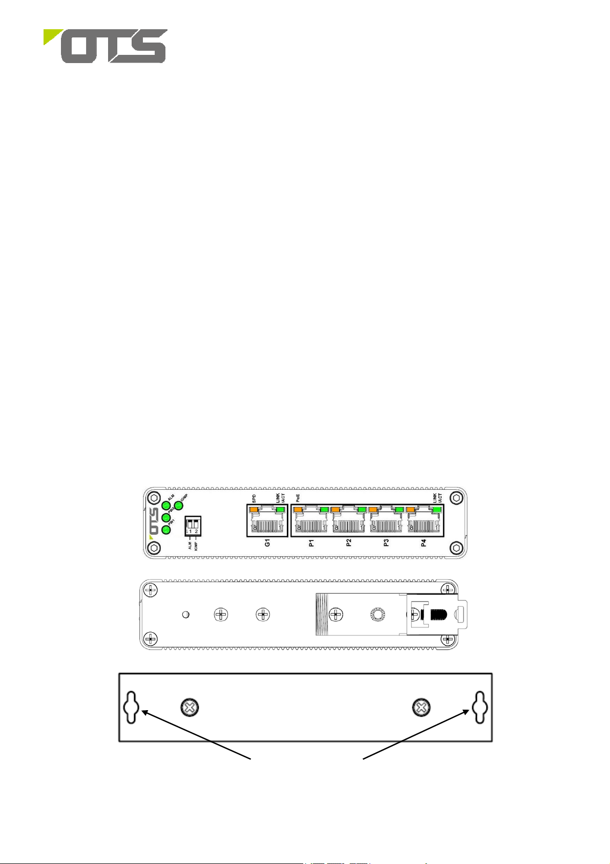
Physical Description
Front Panel
Rear Panel (Din-Rail)
Rear Panel (Wall mount)
Mounting holes
1 V1.1
Page 2
ET5200PpH-DR
Hardened IP CCTV Self-Configured 5-port 10/100/1000Base-T with 4-port PoE+ Ethernet Switch
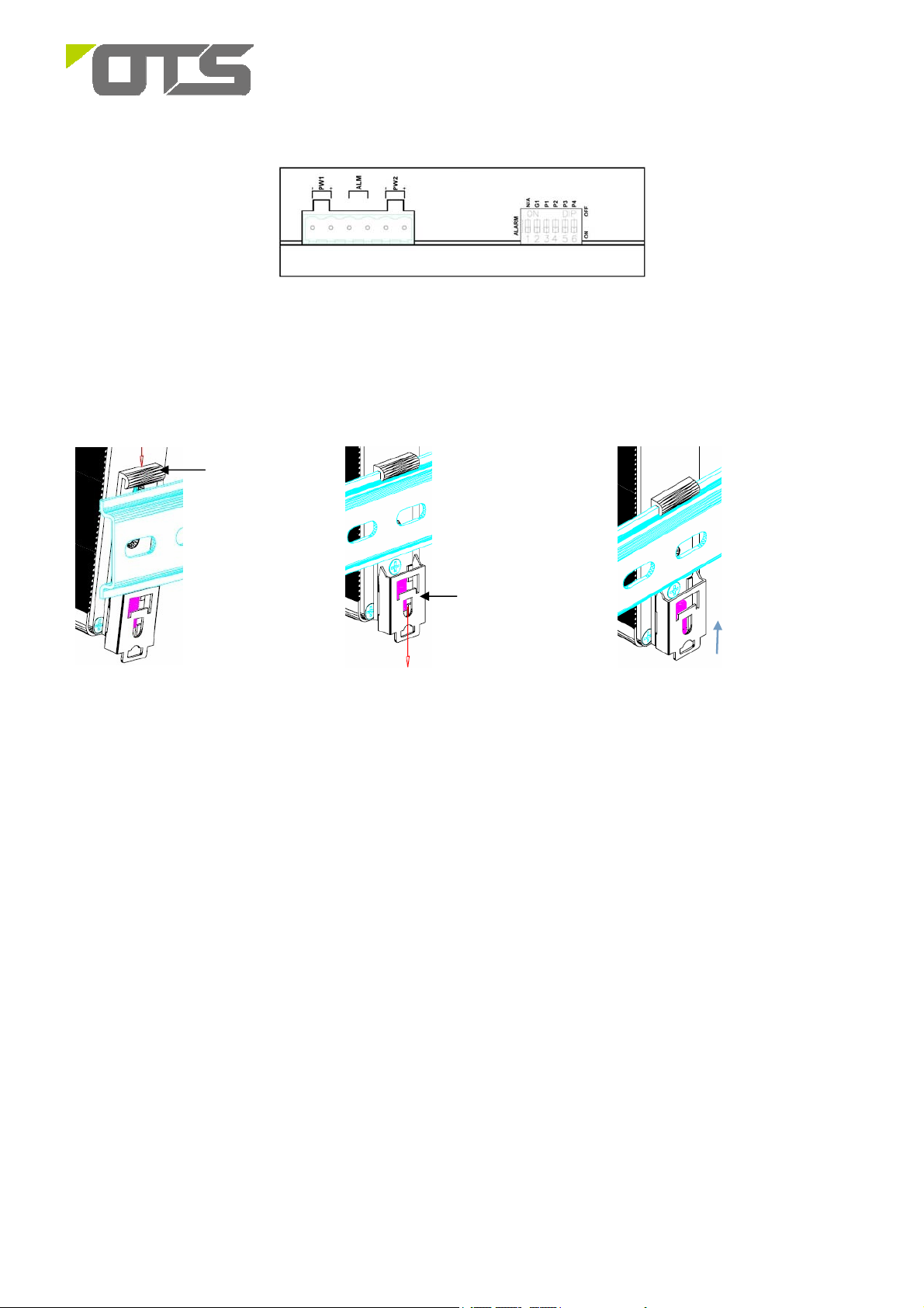
Left Side view
Installation
Din-rail Installation
ET5200PpH-DR can be installed on a DIN rail. Installation steps are as follows:
Top
Hook
Locking
Slide
1. Put the switch close to the
DIN rail track. Lock the top
hook of the DIN rail clip on the
upper side of the track.
Removal:
1. Pull down the locking slide and pull out the lower part of the DIN rail clip until it leaves the track.
2. Lift up the top hook of the clip until the switch separates from the track.
2. Press the switch until
the locking slide moves
downward and a “click”
sound is heard.
3. The locking slide is then
moved back to its original
position. The switch is securely
locked onto the track.
2 V1.1
Page 3

ET5200PpH-DR
Hardened IP CCTV Self-Configured 5-port 10/100/1000Base-T with 4-port PoE+ Ethernet Switch
Wall-mount Installation
1. Remove the screws to
take out the DIN rail clip
from the switch.
2. Tighten the screws to affix the
wall mount plate and the switch
together.
3. Mount the switch on the wall
or on a flat surface with 2 screws
through the mounting holes to
secure it into position.
Mounting
Holes
Setup
1. Connect one end of each Ethernet cable to its corresponding port on the ET5200PpH-DR. Connect
the other end to the network equipment (IP camera, Switch or PC).
2. Connect the ET5200PpH-DR to the power supply. Ensure the power supply in connected to a power
source and the PWR indicator is ON. If not, please ensure that the power cable is connected
properly and the power supply is functioning normally.
After all cables are connected, the indicators will be lit as per port status LEDs (page 4).
Interface
RJ-45 Pin Assignment
Pin Signal Name
1
TP0+ Positive (VCC+)
2
TP0- Positive (VCC+)
3
TP1+ Negative (VCC-)
4
TP2+
5
TP2-
6
TP1- Negative (VCC-)
7
TP3+
8
TP3-
3 V1.1
Page 4

ET5200PpH-DR
Hardened IP CCTV Self-Configured 5-port 10/100/1000Base-T with 4-port PoE+ Ethernet Switch
Power and Alarm Connection:
Pin
Description
V1 - V1 + ALM V2 - V2 +
Power Input
Cable Connections
Signal Type Cable Type Connector
Ethernet
Power supply 1
Power supply 2
ALM
LED Indicators
Indicator Color Status Description
PW1
PW2
ALM
IGMP
GND
Cat. 5 or above RJ45
Power cable
Power cable
2 wire
Green
Green
Green ON On when one of the power supplies are off
Green
+48~57V
(DC)
ON Powered on
ON Powered on
ON Enable IGMP Snooping
OFF Disable IGMP Snooping
Normal
Open
GND
+48~57V
(DC)
6-pin Terminal Block(Pin 1/2)
6-pin Terminal Block(Pin 5/6)
6-pin Terminal Block(Pin 3/4)
PoE Port
(P1-P4)
LINK/ACT
G1 Port SPD
Dip Switch
ALM
IGMP
Port
ON PoE is activated.
PoE
ON Enable Power Failure Alarm (Default setting)
OFF Disable Power Failure Alarm
ON Enable IGMP Snooping (Default setting)
OFF Disable IGMP Snooping
ON Enable Port Failure Alarm
OFF Disable Port Failure Alarm
Amber
Green
Amber
Blinking A Power Device (PD) is being detected.
OFF No device is connected/ the connected device is not a PD.
ON A network device is connected
Blinking The connected device is transmitting/ receiving data.
OFF No network device is connected
ON Ethernet link at 1000Mbps.
OFF Ethernet link at 10/100Mbps or off link.
4 V1.1
Page 5

ET5200PpH-DR
Hardened IP CCTV Self-Configured 5-port 10/100/1000Base-T with 4-port PoE+ Ethernet Switch
Dimensions of the ET5200PpH-DR (Unit: mm)
Functional Description
2048 MAC address
1M bits buffer memory
Supports 9K Bytes Jumbo Frame
Supports Energy Efficient Ethernet IEEE802.3az
Supports IEEE 802.3at Power over Ethernet (PoE)
Support 10/100/1000Mbps-Full/Half-duplex, Auto-negotiation, Auto-MDI/MDIX
Supports Light Hardware IGMP V1, V2, V3; DIP switch selectable
Support Relay output (Dry Contact, 1A@DC 24V) for power fail alarm; DIP switch selectable.
-40°C to 75°C ( -40°F to 167°F) operating temperature range
Supports Wall-mount and DIN-Rail installation
Manual Earth Green manual is available in our website. www.ot-systems.com
5 V1.1
 Loading...