

American Fibertek ET42202M-S-PD User Manual

ET42202M-S-PD
SFP Combo Optical Ethernet Switch with AC + DC inputs
L2+ Managed 20-port 100Base-FX/1000Base-X SFP + 4-port 10/100/1000Base-T or 100/1000Base-FX

ET42202M-S-PD
100/1000Base-FX SFP Combo Optical Ethernet Switch with AC + DC inputs
L2+ Managed 20-port 100Base-FX/1000Base-X SFP + 4-port 10/100/1000Base-T or
LEGAL
The information in this publication has been carefully checked and is believed to be entirely
accurate at the time of publication. Our company assumes no responsibility, however, for
possible errors or omissions, or for any consequences resulting from the use of the
information contained herein. Our company reserves the right to make changes in its products
or product specifications with the intent to improve function or design at any time and
without notice and is not required to update this documentation to reflect such changes.
Our company makes no warranty, representation, or guarantee regarding the suitability of its
products for any particular purpose, nor do we assume any liability arising out of the
application or use of any product and specifically disclaims any and all liability, including
without limitation any consequential or incidental damages.
Our products are not designed, intended, or authorized for use in systems or applications
intended to support or sustain life, or for any other application in which the failure of the
product could create a situation where personal injury or death may occur. Should the Buyer
purchase or use our product for any such unintended or unauthorized application, the Buyer
shall indemnify and hold our company and its officers, employees, subsidiaries, affiliates, and
distributors harmless against all claims, costs, damages, expenses, and reasonable attorney
fees arising out of, either directly or indirectly, any claim of personal injury or death that may
be associated with such unintended or unauthorized use, even if such claim alleges that our
company was negligent regarding the design or manufacture of said product.
www.ot-systems.com Ver.1.0
i

ET42202M-S-PD
100/1000Base-FX SFP Combo Optical Ethernet Switch with AC + DC inputs
L2+ Managed 20-port 100Base-FX/1000Base-X SFP + 4-port 10/100/1000Base-T or
About This Manual
Copyright
.
Purpose
Audience
CONVENTIONS
Disclaimer
FCC Warning
Copyright © 2015 Manufacture Technology Corp. All rights reserved.
The products and programs described in this User’s Manual are licensed
products of Manufacture Technology, This User’s Manual contains proprietary
information protected by copyright, and this User’s Manual and all
accompanying hardware, software and documentation are copyrighted. No
parts of this User’s manual may be copied, photocopied, reproduced,
translated or reduced to any electronic medium or machine-readable from by
any means by electronic or mechanical. Including photocopying, recording, or
information storage and retrieval systems, for any purpose other than the
purchaser’s personal use, and without the prior express written permission of
Manufacture Technology.
This manual gives specific information on how to operate and use the
management functions of the ET42202M-S-PD
The Manual is intended for use by network administrators who are
responsible for operating and maintaining network equipment; consequently,
it assumes a basic working knowledge of general switch functions, the
Internet Protocol (IP), and Simple Network Management Protocol (SNMP).
The following conventions are used throughout this manual to show
information.
Manufacture Technology does not warrant that the hardware will work
properly in all environments and applications, and marks no warranty and
representation, either implied or expressed, with respect to the quality,
performance, merchantability, or fitness for a particular purpose. Manufacture
disclaims liability for any inaccuracies or omissions that may have occurred.
Information in this User’s Manual is subject to change without notice and
does not represent a commitment on the part of Manufacture. Manufacture
assumes no responsibility for any inaccuracies that may be contained in this
User’s Manual. Manufacture makes no commitment to update or keep
current the information in this User’s Manual, and reserves the righter to
make improvements to this User’s Manual and /or to the products described
in this User’s Manual, at any time without notice.
This equipment has been tested and found to comply with the limits for a
Class B digital device, pursuant to Part 15 of the FCC Rules. These limits are
designed to provide reasonable protection against harmful interference when
the equipment is operated in a commercial environment. This equipment
generates, uses, and can radiate radio frequency energy and, if not installed
and used in accordance with the Instruction manual, may cause harmful
interference to radio communications.
www.ot-systems.com Ver.1.0
ii

ET42202M-S-PD
Emph
asizes important
inform
ation or calls y
our
Alerts
you to a potential
hazard
that
could
cause
Alert
s you to a potential hazar
d that
coul
d cause
loss
100/1000Base-FX SFP Combo Optical Ethernet Switch with AC + DC inputs
FCC Caution
CE mark
Warning
L2+ Managed 20-port 100Base-FX/1000Base-X SFP + 4-port 10/100/1000Base-T or
To assure continued compliance (example-use only shielded interface cables
when connection to computer or peripheral devices). Any changes or
modifications not expressly approved by the party responsible for compliance
could void the user’s authority to operate the equipment. This device
complies with Part 15 of the FCC Rules. Operation is subject to the Following
two conditions: (1) This device may not cause harmful interference, and (2)
this device must accept any interference received, including interference that
may cause undesired operation.
This is a Class B device, In a domestic environment, this product may cause
radio interference, in which case the user may be required to take adequate
measures.
N
OTE
:
attention to related features or instructions.
W
ARNING
personal injury.
:
C
AUTION
of data, or damage the system or equipment.
:
www.ot-systems.com Ver.1.0
i

ET42202M-S-PD
100/1000Base-FX SFP Combo Optical Ethernet Switch with AC + DC inputs
L2+ Managed 20-port 100Base-FX/1000Base-X SFP + 4-port 10/100/1000Base-T or
Table of Contents
Revision History ................................................................................................................................................ ix
INTRODUCTION ................................................................................................................ 1
CHAPTER 1 OPERATION OF WEB-BASED MANAGEMENT ............................................ 2
CHAPTER 2 SYSTEM CONFIGURATION ........................................................................ 6
2-1 System ....................................................................................................................................................... 6
2-1.1 Package Contents ...................................................................................................................................... 6
2-1.2 Front of the Switch ................................................................................................................................... 6
2-1.3 Connecting to AC Power Source ............................................................................................................... 6
2-1.4 Port and system status LEDs ..................................................................................................................... 7
2-1.5 Console Connection .................................................................................................................................. 8
2-1.6 Information ............................................................................................................................................... 8
2-1.7 IP ............................................................................................................................................................... 7
2-1.8 NTP ......................................................................................................................................................... 10
2-1.9 Time ........................................................................................................................................................ 11
2-1.10 Log ........................................................................................................................................................ 13
2-2 Green Ethernet ........................................................................................................................................ 14
2-3 Ports Configuration .................................................................................................................................. 18
2-3.1 Ports ........................................................................................................................................................ 18
2-3.2 Ports Description .................................................................................................................................... 21
2-4DHCP ........................................................................................................................................................ 22
2-4.1 Server ...................................................................................................................................................... 22
2-4.1.1 Mode ............................................................................................................................................. 22
2-4.1.2 Excluded IP .................................................................................................................................. 24
2-4.1.3 Pool ............................................................................................................................................... 25
2-4.2 Snooping ................................................................................................................................................. 27
2-4.3 Relay ....................................................................................................................................................... 29
2-5 Security .................................................................................................................................................... 31
2-5.1 Switch ..................................................................................................................................................... 31
2-5.1.1 Users ............................................................................................................................................. 31
2-5.1.2 Privilege Level ............................................................................................................................. 33
2-5.1.3 Authentication Method ................................................................................................................ 35
2-5.1.4 SSH ............................................................................................................................................... 36
2-5.1.5 HTTPs ........................................................................................................................................... 37
2-5.1.6 Access Management .................................................................................................................. 38
2-5.1.7 SNMP............................................................................................................................................ 40
2-5.1.8 RMON ........................................................................................................................................... 55
2-5.2 Network .................................................................................................................................................. 61
2-5.2.1 Limit Control ................................................................................................................................. 61
2-5.2.2 NAS ............................................................................................................................................... 65
2-5.2.3 ACL ............................................................................................................................................... 73
2-5.2.4 IP Source Guard ......................................................................................................................... 80
2-5.2.5 ARP Inspection ............................................................................................................................ 84
2-5.3 AAA ......................................................................................................................................................... 92
2-5.3.1 RADIUS ........................................................................................................................................ 92
2-5.3.2 TACACS+ ..................................................................................................................................... 95
2-6 Aggregation ............................................................................................................................................. 97
2-6.1 Static ....................................................................................................................................................... 97
www.ot-systems.com Ver.1.0
iv

ET42202M-S-PD
100/1000Base-FX SFP Combo Optical Ethernet Switch with AC + DC inputs
2-6.2 LACP ...................................................................................................................................................... 100
L2+ Managed 20-port 100Base-FX/1000Base-X SFP + 4-port 10/100/1000Base-T or
2-7 Loop Protection ..................................................................................................................................... 102
2-8 Spanning Tree ........................................................................................................................................ 104
2-8.1 Bridge Setting ........................................................................................................................................ 104
2-8.2 MSTI Mapping ....................................................................................................................................... 107
2-8.3 MSTI Priorities....................................................................................................................................... 109
2-8.4 CIST Ports .............................................................................................................................................. 110
2-8.5 MSTI Ports ............................................................................................................................................. 112
2-9 IPMC Profile ........................................................................................................................................... 114
2-9.1 Profile Table .......................................................................................................................................... 114
2-9.1.1 IPMC Profile Rule Settings Table ........................................................................................... 115
2-9.2 Address Entry ........................................................................................................................................ 117
2-10MVR ...................................................................................................................................................... 119
2-11 IPMC .................................................................................................................................................... 122
2-11.1 IGMP Snooping ................................................................................................................................... 122
2-11.1.1 Basic Configuration ................................................................................................................. 122
2-11.1.2 VLAN Configuration ................................................................................................................ 124
2-11.1.3 Port Filtering Profile ................................................................................................................ 126
2-11.2 MLD Snooping ..................................................................................................................................... 128
2-11.2.1 Basic Configuration ................................................................................................................. 128
2-11.2.2 VLAN Configuration ................................................................................................................ 131
2-11.2.3 Port Group Filtering ................................................................................................................ 133
2-12 LLDP ..................................................................................................................................................... 134
2-12.1 LLDP Configuration ............................................................................................................................. 134
2-12.2 LLDP-MED Configuration .................................................................................................................... 137
2-13 MAC Table ............................................................................................................................................ 143
2-14 VLANs .................................................................................................................................................. 145
2-15 Private VLANs ...................................................................................................................................... 149
2-15.1 VLAN Membership .............................................................................................................................. 149
2-15.2 Port Isolation....................................................................................................................................... 151
2-16 VCL ....................................................................................................................................................... 152
2-16.1 MAC-based VLAN ................................................................................................................................ 152
2-16.2 Protocol -based VLAN ......................................................................................................................... 154
2-16.2.1 Protocol to Group .................................................................................................................... 154
2-16.2.2 Group to VLAN ........................................................................................................................ 156
2-16.3 IP Subnet-based VLAN ........................................................................................................................ 157
2-17 VOICE VLAN ......................................................................................................................................... 159
2-17.1 Configuration ...................................................................................................................................... 159
2-17.2 OUI ...................................................................................................................................................... 161
2-18 QoS ...................................................................................................................................................... 162
2-18.1 Port Classification ............................................................................................................................... 162
2-18.2 Port Policing ........................................................................................................................................ 164
2-18.4 Port Schedulers ................................................................................................................................... 165
2-18.5 Port Shaping ........................................................................................................................................ 168
2-18.6 Port Tag Remarking ............................................................................................................................. 171
2-18.7 Port DSCP ............................................................................................................................................ 174
2-18.8 DSCP-Based QoS ................................................................................................................................. 176
2-18.9 DSCP Translation ................................................................................................................................. 178
www.ot-systems.com Ver.1.0
v

ET42202M-S-PD
100/1000Base-FX SFP Combo Optical Ethernet Switch with AC + DC inputs
2-18.10 DSCP Classification ............................................................................................................................ 180
2-18.11 QoS Control List Configuration ......................................................................................................... 182
2-18.12 Storm Control ................................................................................................................................... 186
2-18.13 WRED ................................................................................................................................................ 188
L2+ Managed 20-port 100Base-FX/1000Base-X SFP + 4-port 10/100/1000Base-T or
2-19 Mirror .................................................................................................................................................. 190
2-20 UPnP .................................................................................................................................................... 192
2-21. GVRP ................................................................................................................................................... 194
2-21.1 Global Config ...................................................................................................................................... 194
2-21.2 Port Config .......................................................................................................................................... 196
2-22. sFlow .................................................................................................................................................. 197
2-23 Switch2go ......................................................................................................................................... 200
2-23.1 Switch2go setting ............................................................................................................................ 200
2-23.2 User Link Management ................................................................................................................... 201
2-23.3 Port Name Service ........................................................................................................................... 203
CHAPTER 3. MONITOR ............................................................................................. 204
3-1 System ................................................................................................................................................... 204
3-1.1 Information ........................................................................................................................................... 204
3-1.3 IP Status ................................................................................................................................................ 206
3-1.4 Log ........................................................................................................................................................ 208
3-1.5 Detailed Log .......................................................................................................................................... 210
3-2 Green Ethernet ...................................................................................................................................... 211
3-2.1 Port Power Savings ............................................................................................................................... 211
3-3 Ports ...................................................................................................................................................... 212
3-3.1 Traffic Overview .................................................................................................................................... 212
3-3.2 Qos Statistics ......................................................................................................................................... 214
3-3.3 QCL Status ............................................................................................................................................. 215
3-3.4 Detailed Statistics.................................................................................................................................. 217
3-4 DHCP ...................................................................................................................................................... 221
3-4.1 Server .................................................................................................................................................... 221
3-4.1.1 Statistics ..................................................................................................................................... 221
3-4.1.2 Binding ........................................................................................................................................ 222
3-4.1.3 Declined IP ................................................................................................................................. 223
3-4.2 Snooping Table ...................................................................................................................................... 224
3-4.3 Relay Statistics ...................................................................................................................................... 225
3-4.4 Detailed Statistics.................................................................................................................................. 227
3-5 Security .................................................................................................................................................. 229
3-5.1 Access Management Statistics .............................................................................................................. 229
3-5.2 Network ................................................................................................................................................ 230
3-5.2.1 Port Security .............................................................................................................................. 230
3-5.2.2 NAS ............................................................................................................................................. 234
3-5.2.3 ACL Status ................................................................................................................................... 241
3-5.2.4 ARP Inspection .......................................................................................................................... 242
3-5.2.5 IP Source Guard ....................................................................................................................... 243
3-5.3 AAA ....................................................................................................................................................... 245
3-5.3.1 RADIUS Overview .................................................................................................................... 245
3-5.3.2 RADIUS Details ......................................................................................................................... 247
3-5.4 Switch ................................................................................................................................................... 252
3-5.4.1 RMON ......................................................................................................................................... 252
www.ot-systems.com Ver.1.0
vi

ET42202M-S-PD
100/1000Base-FX SFP Combo Optical Ethernet Switch with AC + DC inputs
3-6 LACP....................................................................................................................................................... 260
3-6.1 System Status ........................................................................................................................................ 260
3-6.2 Port Status ............................................................................................................................................ 261
3-6.3 Port Statistics ........................................................................................................................................ 263
L2+ Managed 20-port 100Base-FX/1000Base-X SFP + 4-port 10/100/1000Base-T or
3-7 Loop Protection ..................................................................................................................................... 264
3-8 Spanning Tree ........................................................................................................................................ 265
3-8.1 Bridge Status ......................................................................................................................................... 265
3-8.2 Port Status ............................................................................................................................................ 266
3-8.3 Port Statistics ........................................................................................................................................ 267
3-9 MVR ....................................................................................................................................................... 268
3-9.1 Statistics ................................................................................................................................................ 268
3-9.2 MVR Channels Groups .......................................................................................................................... 269
3-9.3 MVR SFM Information .......................................................................................................................... 271
3-10 IPMC .................................................................................................................................................... 273
3-10.1 IGMP Snooping ................................................................................................................................... 273
3-10.1.1 Status........................................................................................................................................ 273
3-10.1.2 Group Information ................................................................................................................... 275
3-10.1.3 IPv4 SFM Information ............................................................................................................ 277
3-10.2 MLD Snooping ..................................................................................................................................... 279
3-10.2.1 Status........................................................................................................................................ 279
3-10.2.2 Group Information ................................................................................................................... 281
3-10.2.3 IPv6 SFM Information ............................................................................................................ 283
3-11 LLDP ..................................................................................................................................................... 285
3-11.1 Neighbour ........................................................................................................................................... 285
3-11.2 LLDP-MED Neighbour ......................................................................................................................... 287
3-11.3 EEE ...................................................................................................................................................... 290
3-11.4 Port Statistics ...................................................................................................................................... 292
3-12 MAC Table ............................................................................................................................................ 294
3-13 VLANs .................................................................................................................................................. 296
3-13.1 VLAN Membership .............................................................................................................................. 296
3-13.2 VLAN Port ............................................................................................................................................ 298
3-14 VCL ....................................................................................................................................................... 300
3-14.1 MAC-based VLAN ................................................................................................................................ 300
3-14.2 Protocol-based VLAN .......................................................................................................................... 301
3-14.2.1 Protocol to Group .................................................................................................................... 301
3-14.2.2 Group to VLAN ........................................................................................................................ 303
3-14.3 IP Subnet-based VLAN ........................................................................................................................ 304
3-15 sFlow ................................................................................................................................................... 305
CHAPTER 4. DIAGNOSTICS ..................................................................................... 307
4-1 Ping ........................................................................................................................................................ 307
4-2 Ping6 ...................................................................................................................................................... 309
4-3 VeriPHY .................................................................................................................................................. 311
4-4 Traceroute.............................................................................................................................................. 312
CHAPTER 5. MAINTENANCE ................................................................................... 313
www.ot-systems.com Ver.1.0
vii

ET42202M-S-PD
100/1000Base-FX SFP Combo Optical Ethernet Switch with AC + DC inputs
5-1 Restart Device ........................................................................................................................................ 313
L2+ Managed 20-port 100Base-FX/1000Base-X SFP + 4-port 10/100/1000Base-T or
5-2 Factory Defaults ..................................................................................................................................... 314
5-3 Firmware ............................................................................................................................................... 315
5-3.1 Firmware upgrade ................................................................................................................................. 315
5-3.2 Firmware Selection ............................................................................................................................... 316
5-4 Configuration ......................................................................................................................................... 317
5-4.1 Save startup-config ............................................................................................................................... 317
5-4.2 Upload .................................................................................................................................................. 318
5-4.3 Download .............................................................................................................................................. 319
5-4.5 Delete.................................................................................................................................................... 321
www.ot-systems.com Ver.1.0
viii

ET42202M-S-PD
Release
Date
Revision
V
1.0 05/03//
2016 A1
100/1000Base-FX SFP Combo Optical Ethernet Switch with AC + DC inputs
L2+ Managed 20-port 100Base-FX/1000Base-X SFP + 4-port 10/100/1000Base-T or
Revision History
www.ot-systems.com Ver.1.0
ix

INTRODUCTION
Overview
In this user’s manual, it will not only tell you how to install and connect your network
system but configure and monitor the ET42202M-S-PD through the web by (RJ-45) serial
interface and Ethernet ports step-by-step. Many explanations in detail of hardware and
software functions are shown as well as the examples of the operation for web-based
interface.
The ET42202M-S-PD, the next generation Web managed switches from Manufacture,
is a portfolio of affordable managed switches that provides a reliable infrastructure for
your business network. These switches deliver more intelligent features you need to
improve the availability of your critical business applications, protect your sensitive
information, and optimize your network bandwidth to deliver information and applications
more effectively. It provides the ideal combination of affordability and capabilities for
entry level networking includes small business or enterprise application and helps you
create a more efficient, better-connected workforce.
ET42202M-S-PD Web Managed Switches provide 24 ports in a single device; the
specification is highlighted as follows.
L2+ features provide better manageability, security, QoS, and performance.
Support IPv4/IPv6 dual stack management
Support SSH/SSL secured management
Support SNMP v1/v2c/v3
Support RMON groups 1,2,3,9
Support sFlow
Support IGMP v1/v2/v3 Snooping
Support MLD v1/v2 Snooping
Support RADIUS and TACACS+ authentication
Support IP Source Guard
Support DHCP Relay (Option 82)
Support DHCP Snooping
Support ACL and QCL for traffic filtering
Support 802.1d(STP), 802.1w(RSTP) and 802.1s(MSTP)
Support LACP and static link aggregation
Support Q-in-Q double tag VLAN
Support GVRP dynamic VLAN
Overview of this user’s manual
Chapter 1 “Operation of Web-based Management”
Chapter 2 “System Configuration”
Chapter 3 “Configuration”
Chapter 4 “Security”
Chapter 5 “Maintenance”
1
Publication date: Sept., 2015
Revision A2

Default
N
:
Chapter 1
Operation of Web-based Management
Initial
Configuration
This chapter instructs you how to configure and manage the
ET42202M-S-PD
can easily access and monitor through any one port of the switch all the
status of the switch, including MIBs status, each port activity, Spanning tree
status, port aggregation status, multicast traffic, VLAN and priority status,
even illegal access record and so on.
T
he default values of the ET42202M-S-PD are listed in the table below:
IP Address
Subnet Mask
Username
Password
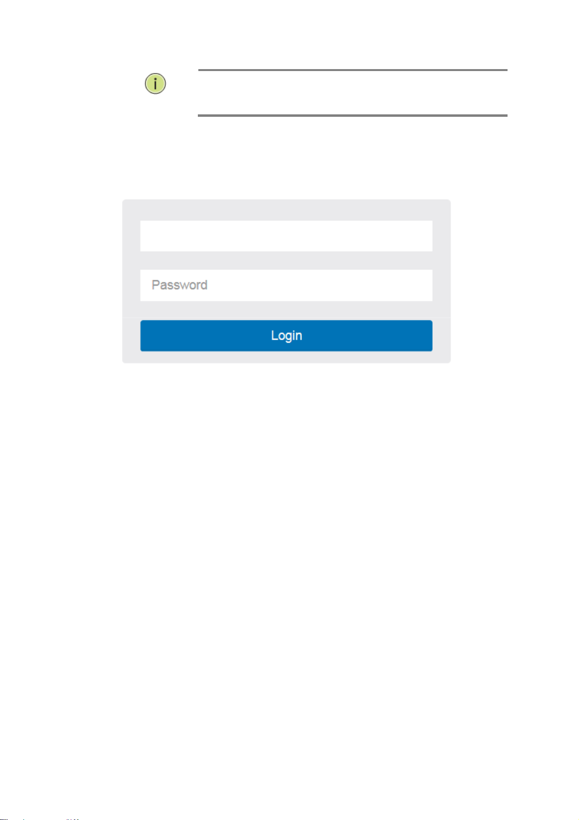
After the ET42202M-S-PD has been finished configuration the it interface,
you can browse it. For instance, type http://192.168.2.1 in the address
row in a browser, it will show the following screen and ask you inputting
username and password in order to login and access authentication.
The default username is “admin” and password is system. For the first
time to use, please enter the default username and password, and then click
the <Login> button. The login process now is completed. In this login menu,
you have to input the complete username and password respectively, the
ET42202M-S-PD will not give you a shortcut to username automatically.
This looks inconvenient,
through the web user interface. With this facility, you
192.168.2.1
255.255.255.0
192.168.2.254
admin
system
but safer.
In the ET42202M-S-PD, allowed two or more users using administrator’s
identity to manage this switch, which administrator to do the last setting, it
will be an available configuration to effect the system.
OTE
When you login the Switch WEB/CLI to manager. You must first type
the Username of the admin and Password of the system, so when
you type after the end Username and password, please press enter.
Management page to enter WEB/CLI.
When you login ET42202M-S-PD switch Web UI management, you
can use both ipv4 ipv6 login to manage
To optimize the display effect, we recommend you use Microsoft IE
6.0 above, Netscape V7.1 above or FireFox V1.00 above and have
the resolution 1024x768. The switch supported neutral web browser
interface
2
Publication date: Sept., 2015
Revision A2
N
:
OTE
Figure 1 The login page
AS ET42202M-S-PD the function enable dhcp, so If you do not have
DHCP server to provide ip addresses to the switch, the Switch
default ip 192.168.2.1
5
Publication date: Sept., 2015
Revision A2
ET42202M-S-PD
100/1000Base-FX SFP Combo Optical Ethernet Switch with AC + DC inputs
L2+ Managed 20-port 100Base-FX/1000Base-X SFP + 4-port 10/100/1000Base-T or
Chapter 2
System Configuration
This chapter describes the entire basic configuration tasks which includes the System
Information and any manage of the Switch (e.g. Time, Account, IP, Syslog and NTP.)
2-1
System
2-1.1 Package Contents
ET42202M-S-PD Managed Fiber Switch x1
Four adhesive rubber feet x1
Mounting Accessory x1
AC Power Cord x1
RS232 DB9 to DB9 Cable x1
You can identify the system by configuring the contact information, name, and location of the
switch.
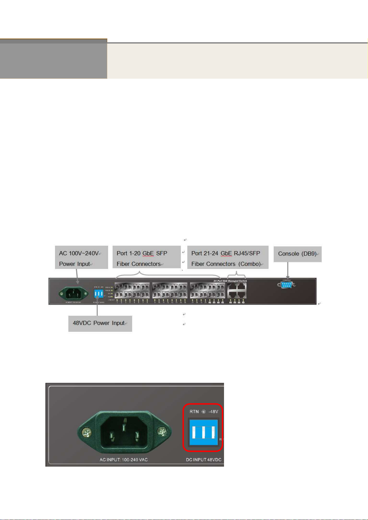
2-1.2 Front of the Switch
2-1.3 Connecting to AC Power Source
DC Power Connecting
You can plug or remove DC power cable through the DC terminal block from external 48VDC
DC power source.
Step1.Insert the DC cable plug directly into the DC terminal block located at the front of
the switch.
www.ot-systems.com Ver.1.0
6
ET42202M-S-PD
For International use, you may need to change the AC
100/1000Base-FX SFP Combo Optical Ethernet Switch with AC + DC inputs
Step2.Plug the other end of the cable into an external DC power source.
Step3.Check the front-panel LEDs as the device is powered on to be sure the POWER LED
is lit. If not, check that the power cable is correctly plugged in.
L2+ Managed 20-port 100Base-FX/1000Base-X SFP + 4-port 10/100/1000Base-T or
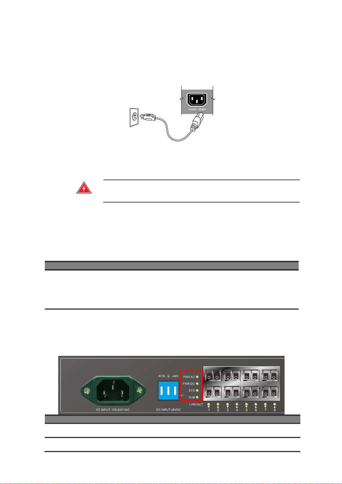
AC Power Connecting
You can plug or remove AC power cord through the AC socket from AC power source.
Step1. Insert the power cable plug directly into the AC Socket located at the back of the
switch.
Step2. Plug the other end of the cable into a grounded, 3-Pin, AC power source.
Step3. Check the front-panel LEDs as the device is powered on to be sure the POWER LED
is lit. If not, check that the power cable is correctly plugged in.
W
ARNING
line cord. You must use a line cord set that has been approved for
the socket type in your country.
:
2-1.4 Port and system status LEDs
The ET42202M-S-PD switch includes a display panel for system and port indications that simplify
installation and network troubleshooting. The LEDs, which are located on left hand side of the front
panel for easy viewing. Details are shown below and described in the following tables.
Port Status LEDs
LED Condition
P1-P24 SFP
Link/Act/Speed
Green/ Amber
Status
Light when Fiber connection with remote device is
good.
Blinks when any traffic is present.
The light is green when linking up 1000Mbps.
The light is Amber when linking up 100Mbps.
P21-P24 TP
Link/Act/Speed
Green/ Amber
Blinks when any traffic is present.
The light is green when linking up 10/1000Mbps.
The light is Amber when linking up 100Mbps.
System Status LED
SYSTEM LED Condition
PWR AC Green Light when power on
PWR DC Green Light when power on
www.ot-systems.com Ver.1.0
Status
7
ET42202M-S-PD
Blinking when system is booting;
N
:
it does not support cross cable for console port
100/1000Base-FX SFP Combo Optical Ethernet Switch with AC + DC inputs
L2+ Managed 20-port 100Base-FX/1000Base-X SFP + 4-port 10/100/1000Base-T or
SYS Green
ALARM Red
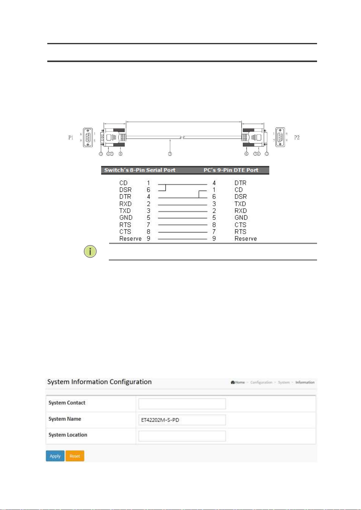
2-1.5 Console Connection
Serial Cable Wiring
Lit when system is coming up.
Always off; until any message about system
error turn the light on.
OTE
2-1.6 Information
The switch system’s contact information is provided here.
Web interface
To configure System Information in the web interface:
1. Click Configuration, System, and Information.
2. Write System Contact, System Name, System Location information in this page.
3. Click Apply
Figure 2-1.6: System Information
Parameter description:
System Contact:
www.ot-systems.com Ver.1.0
8

ET42202M-S-PD
100/1000Base-FX SFP Combo Optical Ethernet Switch with AC + DC inputs
The textual identification of the contact person for this managed node, together
with information on how to contact this person. The allowed string length is 0 to
128, and the allowed content is the ASCII characters from 32 to 126.
System name:
An administratively assigned name for this managed node. By convention, this is
the node's fully-qualified domain name. A domain name is a text string drawn
from the alphabet (A-Za-z), digits (0-9), minus sign (-). No space characters are
permitted as part of a name. The first character must be an alpha character. And
the first or last character must not be a minus sign. The allowed string length is 0
to 128.
System Location:
The physical location of this node(e.g., telephone closet, 3rd floor). The allowed
string length is 0 to 128, and the allowed content is the ASCII characters from 32
to 126.
L2+ Managed 20-port 100Base-FX/1000Base-X SFP + 4-port 10/100/1000Base-T or
www.ot-systems.com Ver.1.0
9
ET42202M-S-PD
L2+ Managed 20-port 100Base-FX/1000Base-X SFP + 4-port 10/100/1000Base-T or
100/1000Base-FX SFP Combo Optical Ethernet Switch with AC + DC inputs
2-1.7 IP
The IPv4 address for the switch could be obtained via DHCP Server for VLAN 1. To manually
configure an address, you need to change the switch's default settings to values that are
compatible with your network. You may also need to establish a default gateway between the
switch and management stations that exist on another network segment.
Configure the switch-managed IP information on this page
Configure IP basic settings, control IP interfaces and IP routes.
The maximum number of interfaces supported is 8 and the maximum number of routes is 32.
Web Interface
To configure an IP address in the web interface:
1. Click Configuration, System, IP.
2. Click Add Interface then you can create new Interface on the switch.
3. Click Add Route then you can create new Route on the switch
4. Click Apply
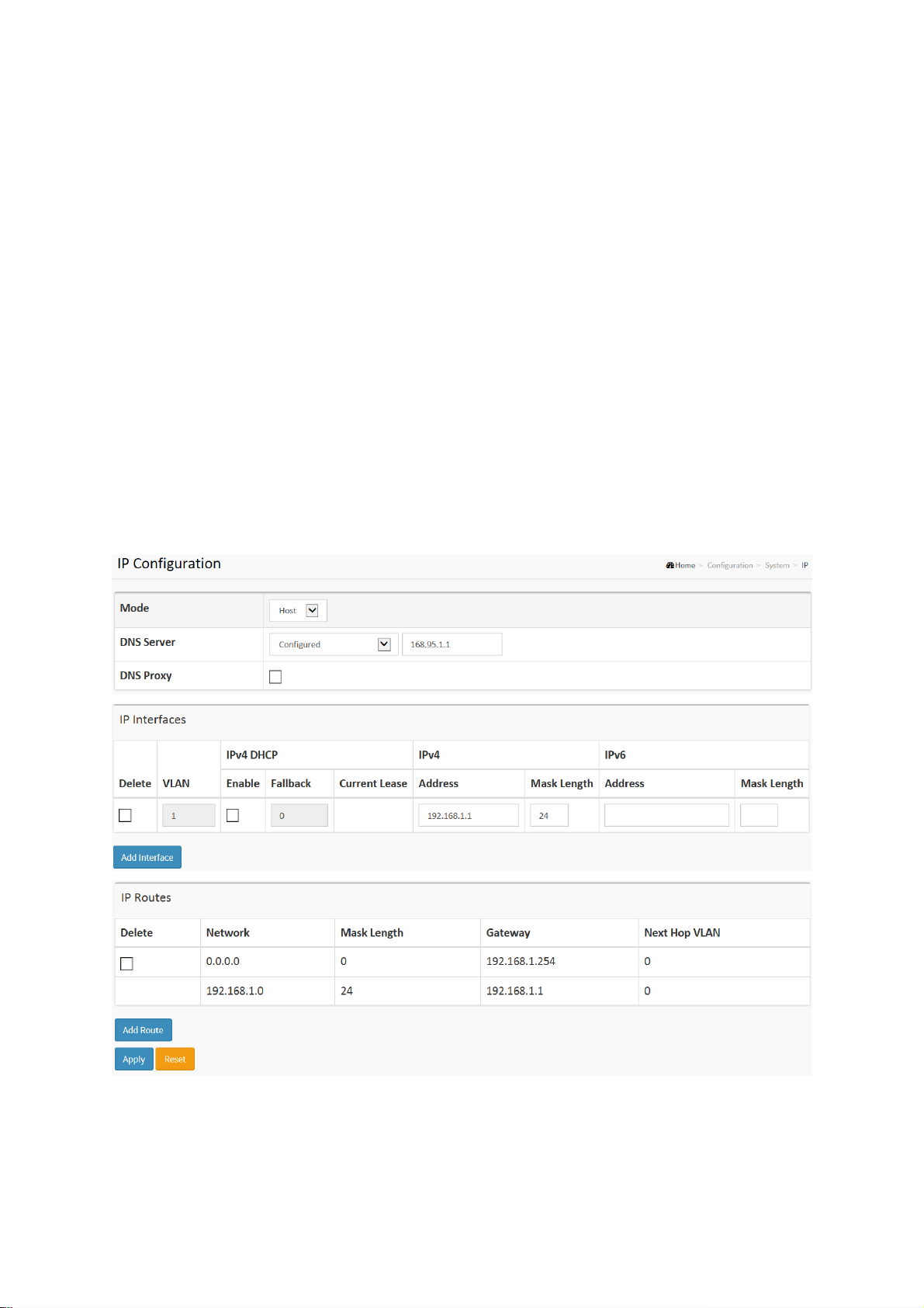
Figure2-1.7: The IP configuration
Parameter description:
IP Configuration
Mode:
Configure whether the IP stack should act as a Host or a Router. In Host mode, IP traffic
between interfaces will not be routed. In Router mode traffic is routed between all
www.ot-systems.com Ver.1.0
7

ET42202M-S-PD
100/1000Base-FX SFP Combo Optical Ethernet Switch with AC + DC inputs
interfaces.
DNS Server
This setting controls the DNS name resolution done by the switch. The following modes are
supported:
• From any DHCP interfaces
• No DNS server
• Configured
• From this DHCP interface
DNS Proxy
When DNS proxy is enabled, system will relay DNS requests to the currently configured
DNS server, and reply as a DNS resolver to the client devices on the network.
IP Interfaces
Delete
L2+ Managed 20-port 100Base-FX/1000Base-X SFP + 4-port 10/100/1000Base-T or
The first DNS server offered from a DHCP lease to a DHCP-enabled interface will be
used.
No DNS server will be used.
Explicitly provide the IP address of the DNS Server in dotted decimal notation.
Specify from which DHCP-enabled interface a provided DNS server should be
preferred.
Select this option to delete an existing IP interface.
VLAN
The VLAN associated with the IP interface. Only ports in this VLAN will be able to access
the IP interface. This field is only available for input when creating an new interface.
IPv4 DHCP Enabled
Enable the DHCP client by checking this box. If this option is enabled, the system will
configure the IPv4 address and mask of the interface using the DHCP protocol. The DHCP
client will announce the configured System Name as hostname to provide DNS lookup.
IPv4 DHCP Fallback Timeout
The number of seconds for trying to obtain a DHCP lease. After this period expires, a
configured IPv4 address will be used as IPv4 interface address. A value of zero disables
the fallback mechanism, such that DHCP will keep retrying until a valid lease is obtained.
Legal values are 0 to 4294967295 seconds.
IPv4 DHCP Current Lease
For DHCP interfaces with an active lease, this column show the current interface address,
as provided by the DHCP server.
IPv4 Address
The IPv4 address of the interface in dotted decimal notation.
If DHCP is enabled, this field is not used. The field may also be left blank if IPv4 operation
on the interface is not desired.
IPv4 Mask
The IPv4 network mask, in number of bits (prefix length). Valid values are between 0 and 30
bits for a IPv4 address.
If DHCP is enabled, this field is not used. The field may also be left blank if IPv4 operation
on the interface is not desired.
IPv6 Address
The IPv6 address of the interface. A IPv6 address is in 128-bit records represented as eight
fields of up to four hexadecimal digits with a colon separating each field (:). For example,
fe80::215:c5ff:fe03:4dc7. The symbol :: is a special syntax that can be used as a shorthand
way of representing multiple 16-bit groups of contiguous zeros; but it can appear only once.
It can also represent a legally valid IPv4 address. For example, ::192.1.2.34.
The field may be left blank if IPv6 operation on the interface is not desired.
IPv6 Mask
www.ot-systems.com Ver.1.0
8

ET42202M-S-PD
100/1000Base-FX SFP Combo Optical Ethernet Switch with AC + DC inputs
The IPv6 network mask, in number of bits (prefix length). Valid values are between 1 and
128 bits for a IPv6 address.
The field may be left blank if IPv6 operation on the interface is not desired.
IP Routes
Delete
Select this option to delete an existing IP route.
Network
The destination IP network or host address of this route. Valid format is dotted decimal
notationor a valid IPv6 notation. A default route can use the value 0.0.0.0or IPv6 :: notation.
Mask Length
The destination IP network or host mask, in number of bits (prefix length). It defines how
much of a network address that must match, in order to qualify for this route. Valid values
are between 0 and 32 bits respectively 128 for IPv6 routes. Only a default route will have a
mask length of 0 (as it will match anything).
Gateway
The IP address of the IP gateway. Valid format is dotted decimal notationor a valid IPv6
notation. Gateway and Network must be of the same type.
Next Hop VLAN (Only for IPv6)
L2+ Managed 20-port 100Base-FX/1000Base-X SFP + 4-port 10/100/1000Base-T or
The VLAN ID (VID) of the specific IPv6 interface associated with the gateway.
The given VID ranges from 1 to 4094 and will be effective only when the corresponding
IPv6 interface is valid.
If the IPv6 gateway address is link-local, it must specify the next hop VLAN for the gateway.
If the IPv6 gateway address is not link-local, system ignores the next hop VLAN for the
gateway.
Buttons
Add Interface:
Click to add a new IP interface. A maximum of 8 interfaces is supported.
Add Route:
Click to add a new IP route. A maximum of 32 routes is supported.
Apply:
Click to save changes.
Reset:
Click to undo any changes made locally and revert to previously saved values.
www.ot-systems.com Ver.1.0
9
ET42202M-S-PD
100/1000Base-FX SFP Combo Optical Ethernet Switch with AC + DC inputs
L2+ Managed 20-port 100Base-FX/1000Base-X SFP + 4-port 10/100/1000Base-T or
2-1.8 NTP
NTP is Network Time Protocol and is used to sync the network time based Greenwich Mean
Time (GMT). If use the NTP mode and select a built-in NTP time server or manually specify an
user-defined NTP server as well as Time Zone, the switch will sync the time in a short after
pressing <Apply> button. Though it synchronizes the time automatically, NTP does not update
the time periodically without user’s processing.
Time Zone is an offset time off GMT. You have to select the time zone first and then perform
time sync via NTP because the switch will combine this time zone offset and updated NTP time
to come out the local time, otherwise, you will not able to get the correct time. The switch
supports configurable time zone from –12 to +13 step 1 hour.
Default Time zone: +8 Hrs.
Web Interface
To configure NTP in the web interface:
1. Click Configuration, System, NTP.
2. Specify the Time parameter in manual parameters.
3. Click Apply.
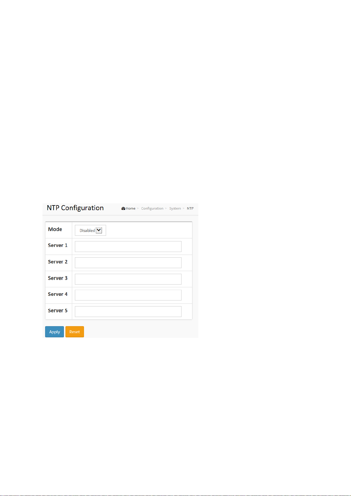
Figure 2-1.8: The NTP configuration
Parameter description:
Mode :
Indicates the NTP mode operation. Possible modes are:
Enabled: Enable NTP client mode operation.
Disabled: Disable NTP client mode operation.
Server 1 to 5 :
Provide the NTP IPv4 or IPv6 address of this switch. IPv6 address is in 128-bit
records represented as eight fields of up to four hexadecimal digits with a colon
separating each field (:). For example, 'fe80::215:c5ff:fe03:4dc7'. The symbol
'::' is a special syntax that can be used as a shorthand way of representing
multiple 16-bit groups of contiguous zeros; but it can only appear once. It can
also represent a legally valid IPv4 address. For example, '::192.1.2.34'.
Buttons
These buttons are displayed on the NTP page:
www.ot-systems.com Ver.1.0
10

ET42202M-S-PD
100/1000Base-FX SFP Combo Optical Ethernet Switch with AC + DC inputs
Apply – Click to save changes.
Reset - Click to undo any changes made locally and revert to previously saved
L2+ Managed 20-port 100Base-FX/1000Base-X SFP + 4-port 10/100/1000Base-T or
value
www.ot-systems.com Ver.1.0
11

2-1.9 Time
The switch provides manual and automatic ways to set the system time via NTP. Manual
setting is simple and you just input “Year”, “Month”, “Day”, “Hour” and “Minute” within the valid
value range indicated in each item.
Web Interface
To configure Time in the web interface:
1. Click Configuration, System and Time
2. Specify the Time parameter.
3. Click Apply.
Figure 2-1.9: The time configuration
11
Publication date: Sept., 2015
Revision A2

ET42202M-S-PD
100/1000Base-FX SFP Combo Optical Ethernet Switch with AC + DC inputs
L2+ Managed 20-port 100Base-FX/1000Base-X SFP + 4-port 10/100/1000Base-T or
Parameter description:
Time Configuration
Clock Source:
There are two modes for configuring how the Clock Source from. Select "Use
Local Settings" : Clock Source from Local Time. Select "Use NTP Server" : Clock
Source from NTP Server.
System Date:
Show the current time of the system. The year of system date limits between
2011 and 2037.
Time Zone Configuration
Time Zone:
Lists various Time Zones world wide. Select appropriate Time Zone from the drop
down and click Apply to set.
Acronym:
User can set the acronym of the time zone. This is a User configurable acronym to
identify the time zone. ( Range : Up to 16 characters )
Daylight Saving Time Configuration
Daylight Saving Time:
This is used to set the clock forward or backward according to the configurations
set below for a defined Daylight Saving Time duration. Select 'Disable' to disable
the Daylight Saving Time configuration. Select 'Recurring' and configure the
Daylight Saving Time duration to repeat the configuration every year. Select
'Non-Recurring' and configure the Daylight Saving Time duration for single time
configuration. ( Default : Disabled ).
www.ot-systems.com Ver.1.0
12

ET42202M-S-PD
The under
“Start Time
S
ettings”
and
“End Time
100/1000Base-FX SFP Combo Optical Ethernet Switch with AC + DC inputs
Recurring Configuration
Start time settings:
Week - Select the starting week number.
Day - Select the starting day.
Month - Select the starting month.
Hours - Select the starting hour.
Minutes - Select the starting minute.
End time settings:
Week - Select the ending week number.
Day - Select the ending day.
Month - Select the ending month.
Hours - Select the ending hour.
Minutes - Select the ending minute.
Offset settings:
Offset - Enter the number of minutes to add during Daylight Saving Time. ( Range:
1 to 1440 )
L2+ Managed 20-port 100Base-FX/1000Base-X SFP + 4-port 10/100/1000Base-T or
Buttons
These buttons are displayed on the NTP page:
Apply – Click to save changes.
Reset - Click to undo any changes made locally and revert to previously saved
2-1.10 Log
The log is a standard for logging program messages . It allows separation of the software that
generates messages from the system that stores them and the software that reports and
analyzes them. It can be used as well a generalized informational, analysis and debugging
messages. It is supported by a wide variety of devices and receivers across multiple platforms.
Web Interface
values.
N
OTE
:
Settings” was displayed what you set on the “Start Time
Settings” and “End Time Settings” field information.
To configure log configuration in the web interface:
1. Click Configuration, System and log.
2. Specify the syslog parameters include IP Address of Syslog server and Port number.
3. Evoke the Syslog to enable it.
4. Click Apply.
www.ot-systems.com Ver.1.0
13
ET42202M-S-PD
100/1000Base-FX SFP Combo Optical Ethernet Switch with AC + DC inputs
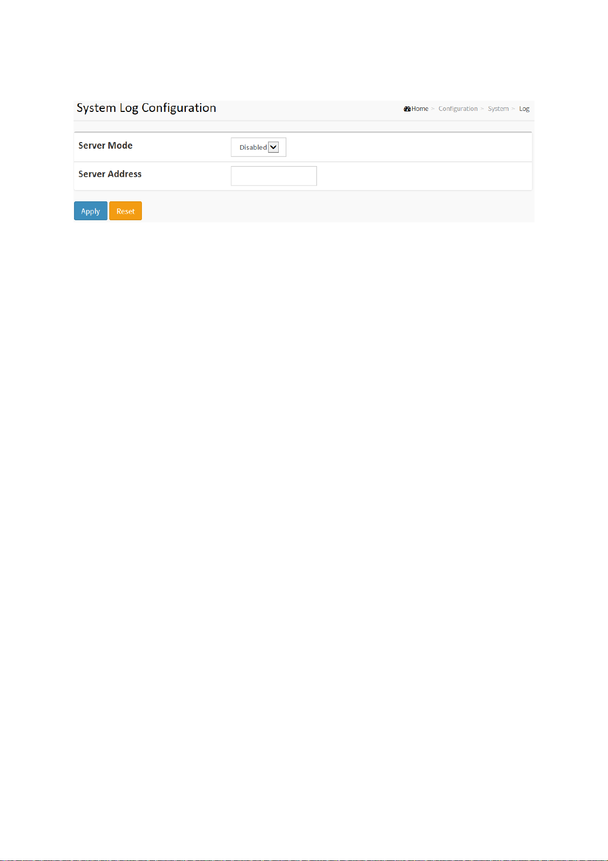
Figure2-1.10: The System Log configuration
Parameter description:
Server Mode :
Indicate the server mode operation. When the mode operation is enabled, the
syslog message will send out to syslog server. The syslog protocol is based on
UDP communication and received on UDP port 514 and the syslog server will not
send acknowledgments back sender since UDP is a connectionless protocol and it
does not provide acknowledgments. The syslog packet will always send out even
if the syslog server does not exist. Possible modes are:
L2+ Managed 20-port 100Base-FX/1000Base-X SFP + 4-port 10/100/1000Base-T or
Enabled: Enable server mode operation.
Disabled: Disable server mode operation.
Server Address :
Indicates the IPv4 hosts address of syslog server. If the switch provide DNS
feature, it also can be a host name.
Syslog Level :
Indicates what kind of message will send to syslog server. Possible modes are:
Info: Send information, warnings and errors.
Warning: Send warnings and errors.
Error: Send errors.
Buttons
These buttons are displayed on the NTP page:
Apply – Click to save changes.
Reset - Click to undo any changes made locally and revert to previously saved
values.
2-2 Green Ethernet
EEE is a power saving option that reduces the power usage when there is low or no traffic
utilization.
EEE works by powering down circuits when there is no traffic. When a port gets data to be
transmitted all circuits are powered up. The time it takes to power up the circuits is named
wakeup time. The default wakeup time is 17 us for 1Gbit links and 30 us for other link speeds.
EEE devices must agree upon the value of the wakeup time in order to make sure that both the
receiving and transmitting device has all circuits powered up when traffic is transmitted. The
devices can exchange wakeup time information using the LLDP protocol.
EEE works for ports in auto-negotiation mode, where the port is negotiated to either 1G or 100
Mbit full duplex mode.
For ports that are not EEE-capable the corresponding EEE checkboxes are grayed out and
www.ot-systems.com Ver.1.0
14
ET42202M-S-PD
100/1000Base-FX SFP Combo Optical Ethernet Switch with AC + DC inputs
thus impossible to enable EEE for.
When a port is powered down for saving power, outgoing traffic is stored in a buffer until the
port is powered up again. Because there are some overhead in turning the port down and up,
more power can be saved if the traffic can be buffered up until a large burst of traffic can be
transmitted. Buffering traffic will give some latency in the traffic.
L2+ Managed 20-port 100Base-FX/1000Base-X SFP + 4-port 10/100/1000Base-T or
Web Interface
To configure a Port Power Saving Configuration in the web interface:
1. Click Configuration, Green Ethernet
2. Evoke to enable or disable the ActiPHY, PerfectReach, EEE and EEE Urgent Queues .
3. Click Apply.
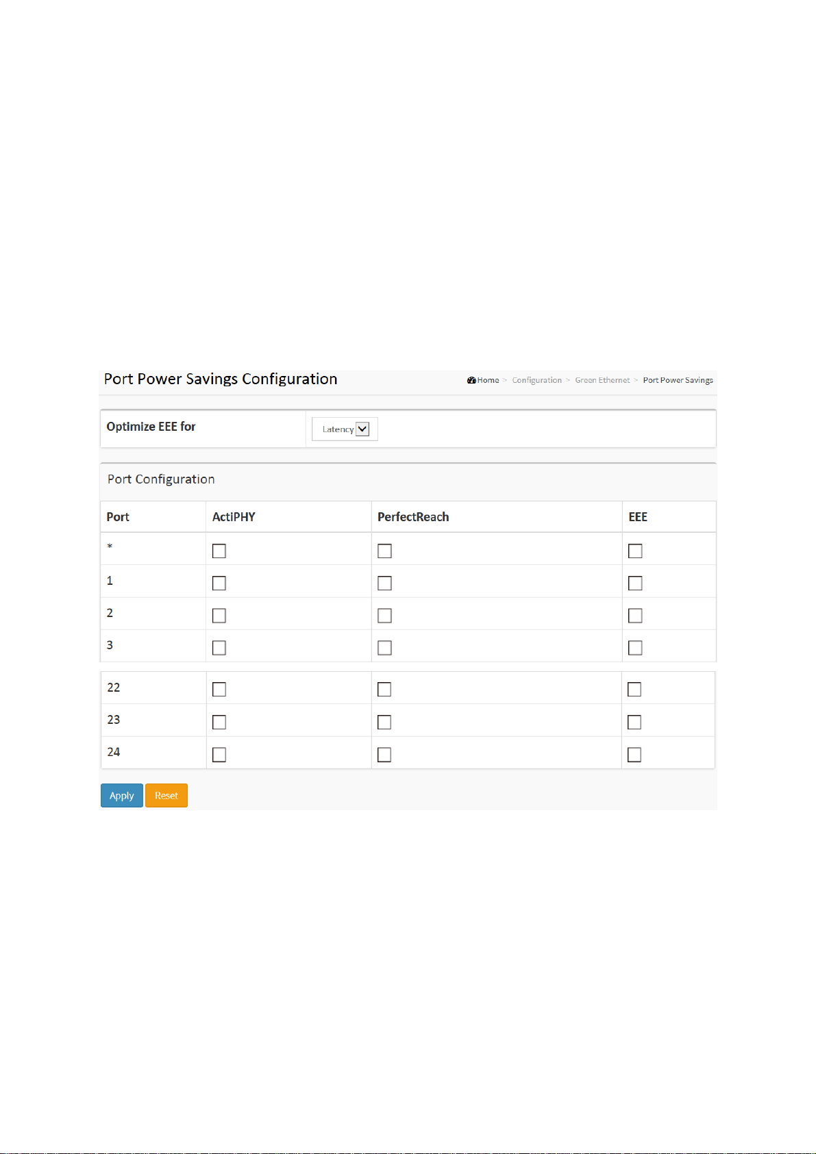
Figure 2-2.1: The Port Power Saving Configuration
Parameter description:
Optimize EEE for
The switch can be set to optimize EEE for either best power saving or least traffic
latency.
Port:
The switch port number of the logical port.
ActiPHY :
Link down power savings enabled.
ActiPHY works by lowering the power for a port when there is no link. The port is
power up for short moment in order to determine if cable is inserted.
www.ot-systems.com Ver.1.0
15

ET42202M-S-PD
100/1000Base-FX SFP Combo Optical Ethernet Switch with AC + DC inputs
PerfectReach :
Cable length power savings enabled.
PerfectReach works by determining the cable length and lowering the power for
ports with short cables.
EEE :
Controls whether EEE is enabled for this switch port.
For maximizing power savings, the circuit isn't started at once transmit data is
ready for a port, but is instead queued until a burst of data is ready to be
transmitted. This will give some traffic latency.
If desired it is possible to minimize the latency for specific frames, by mapping the
frames to a specific queue (done with QOS), and then mark the queue as an
urgent queue. When an urgent queue gets data to be transmitted, the circuits will
be powered up at once and the latency will be reduced to the wakeup time.
L2+ Managed 20-port 100Base-FX/1000Base-X SFP + 4-port 10/100/1000Base-T or
www.ot-systems.com Ver.1.0
16
2-3 Ports Configuration
The section describes to configure the Port detail parameters of the switch. Others you could
using the Port configure to enable or disable the Port of the switch. Monitor the ports content or
status in the function.
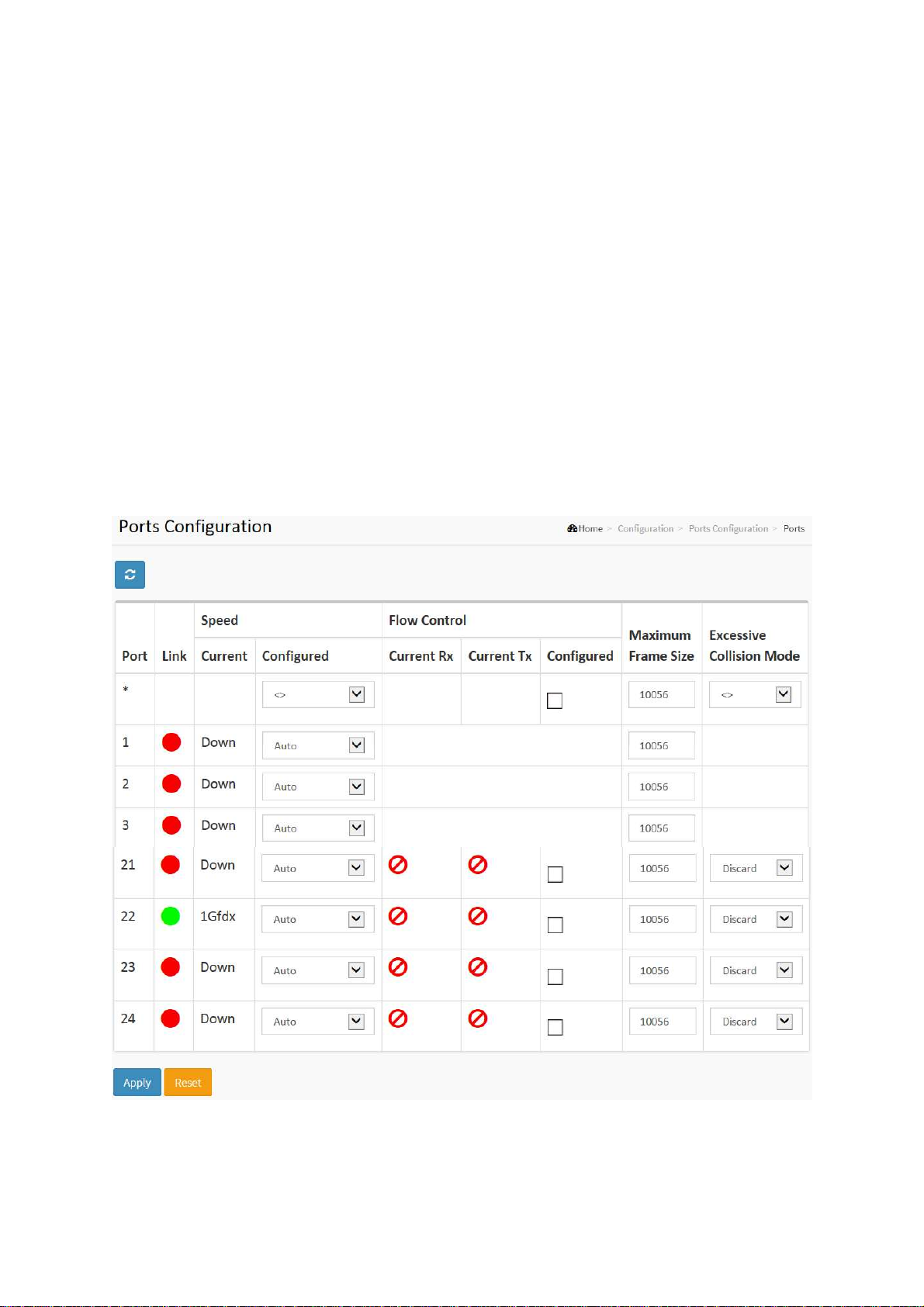
2-3.1 Ports
This page displays current port configurations. Ports can also be configured here.
Web Interface
To configure a Current Port Configuration in the web interface:
1. Click Configuration, Ports Configuration, and Ports
2. Specify the Speed Configured, Flow Control, Maximum Frame size, Excessive Collision
mode and Power Control.
3. Click Apply.
Figure 2-3.1: The Port Configuration

ET42202M-S-PD
100/1000Base-FX SFP Combo Optical Ethernet Switch with AC + DC inputs
Parameter description:
Port :
This is the logical port number for this row.
Link :
The current link state is displayed graphically. Green indicates the link is up and
red that it is down.
Current Link Speed :
Provides the current link speed of the port.
Configured Link Speed :
Selects any available link speed for the given switch port. Only speeds supported
by the specific port is shown. Possible speeds are:
Disabled - Disables the switch port operation.
Auto - Port auto negotiating speed with the link partner and selects the highest
speed that is compatible with the link partner.
10Mbps HDX - Forces the cu port in 10Mbps half duplex mode.
10Mbps FDX - Forces the cu port in 10Mbps full duplex mode.
L2+ Managed 20-port 100Base-FX/1000Base-X SFP + 4-port 10/100/1000Base-T or
100Mbps HDX - Forces the cu port in 100Mbps half duplex mode.
100Mbps FDX - Forces the cu port in 100Mbps full duplex mode.
1Gbps FDX - Forces the port in 1Gbps full duplex
2.5Gbps FDX - Forces the Serdes port in 2.5Gbps full duplex mode.
SFP_Auto_AMS - Automatically determines the speed of the SFP. Note: There is
no standardized way to do SFP auto detect, so here it is done by reading the SFP
rom. Due to the missing standardized way of doing SFP auto detect some SFPs
might not be detectable. The port is set in AMS mode. Cu port is set in Auto mode.
100-FX - SFP port in 100-FX speed. Cu port disabled.
100-FX_AMS - Port in AMS mode. SFP port in 100-FX speed. Cu port in Auto
mode.
1000-X - SFP port in 1000-X speed. Cu port disabled.
1000-X_AMS - Port in AMS mode. SFP port in 1000-X speed. Cu port in Auto mode.
Ports in AMS mode with 1000-X speed has Cu port preferred. Ports in AMS mode
with 100-FX speed has fiber port preferred.
Flow Control :
When Auto Speed is selected on a port, this section indicates the flow control
capability that is advertised to the link partner. When a fixed-speed setting is
selected, that is what is used. The Current Rx column indicates whether pause
frames on the port are obeyed, and the Current Tx column indicates whether
pause frames on the port are transmitted. The Rx and Tx settings are determined
by the result of the last Auto-Negotiation.
Check the configured column to use flow control. This setting is related to the
setting for Configured Link Speed.
Maximum Frame Size :
Enter the maximum frame size allowed for the switch port, including FCS.
Excessive Collision Mode :
Configure port transmit collision behavior.
Discard: Discard frame after 16 collisions (default).
Restart: Restart backoff algorithm after 16 collisions.
www.ot-systems.com Ver.1.0
19
 Loading...