

Page 1

© Copyright 2013, American Fibertek, Inc. 082613JPM
Instruction Manual
DRBK-1
DIN Rail Adapter Bracket
Page 2
2
INSTALLATION INSTRUCTIONS
INTRODUCTION
Thank you for purchasing your American Fibertek DRBK-1 DIN Rail Adapter Bracket.
Please take a few minutes to read these installation instructions in order to obtain the
maximum performance from this product.
FUNCTIONAL DESCRIPTION
The DRBK-1 provides DIN Rail mounting to a wide variety of American Fibertek fiber
optic and network products. The DRBK-1 is sized to accommodate the 4¼” x 4¼”
package.
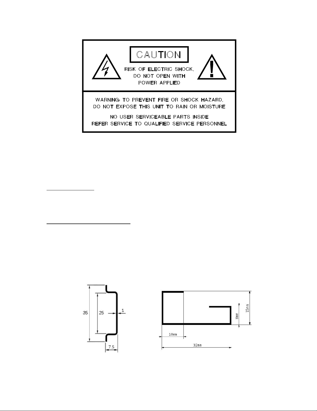
The DRBK-1 is compatible with 35mm Top Hat type rails (EN 50022, BS 5584, DIN
46277-3) and 32mm G-type rail (EN 50035, BS 5825, DIN 46277-1).
35mm Top Hat 32mm G-type
Page 3

3
INSTALLATION
THIS INSTALLATION SHOULD BE MADE BY A QUALIFIED SERVICE PERSON AND
SHOULD CONFORM TO THE NATIONAL ELECTRICAL CODE, ANSI/NFPA 70 AND
LOCAL CODES.
Place the DRBK-1 on a flat surface. Align the unit to be mounted with the four threaded
holes on the plate. The unit may be mounted with the connectors facing up or down. It is
recommended to face the optical connectors down to reduce the chance of dust or other
foreign materials from entering the optical receptacle. Secure the unit with the four
#6x32 screws and lock washers provided.
To mount the assembled unit to the rail, hold the DRBK-1 vertically with the unit to the
left side. Align the top of the rail with the appropriate slot of the plastic DIN mounting
component for the type of rail used. On the upper part of the DIN rail clip there is a
downward facing slot for the Top Hat rail and an upward facing slot for the G Rail. Keep
the unit tilted upwards to align the upper slot. With slight pressure, keep the clip in the
upper slot while tilting the unit downwards until it snaps into place on the rail.
To remove the unit, use your index finger to apply slight downward pressure on the
bottom tab of the DIN clip. Tilt the DRBK-1 upwards and lift away from the rail. If you
can not fit your finger behind the unit, you may apply firm upwards pressure on the
assembly and tilt the unit downwards to clear the top slot of the rail a bring the unit away
from the rail.
Page 4

4
LIFETIME WARRANTY INFORMATION
American Fibertek, Inc warrants that at the time of delivery the products delivered will be
free of defects in materials and workmanship. Defective products will be repaired or
replaced at the exclusive option of American Fibertek. A Return Material Authorization
(RMA) number is required to send the products back in case of return. All returns must
be shipped prepaid. This warranty is void if the products have been tampered with. This
warranty shall be construed in accordance with New Jersey law and the courts of New
Jersey shall have exclusive jurisdiction over this contract. EXCEPT FOR THE
FOREGOING WARRANTY, THERE IS NO WARRANTY OF MERCHANTABILITY OR
FITNESS FOR A PARTICULAR PURPOSE OR OTHERWISE, EXPRESSED OR
IMPLIED, WHICH EXTENDS BEYOND THE WARRANTY SET FORTH IN THIS
AGREEMENT. In any event, American Fibertek will not be responsible or liable for
contingent, consequential, or incidental damages. No agreement or understanding,
expressed or implied, except as set forth in this warranty, will be binding upon American
Fibertek unless in writing, signed by a duly authorized officer of American Fibertek.
SERVICE INFORMATION
There are no user serviceable parts inside the unit.
In the event that service is required to this unit, please direct all inquiries to:
American Fibertek, Inc. Phone: (877) 234-7200
120 Belmont Drive Phone: (732) 302-0660
Somerset, NJ 08873 FAX (732) 302-0667
E-mail: techinfo@americanfibertek.com
 Loading...