

Page 1
Commander
C10e-PoE/C10p-PoE
Operations
Manual
1
Page 2

FCC Caution and Warnings
Caution:
Before attempting to connect or operate this product, please read the label on the top and bottom.
Note:
This equipment has been tested and found to comply with the limits for a Class A digital device,
pursuant to Part 15 of the FCC Rules. These limits are designed to provide reasonable protection
against harmful interference when the equipment is operated in a commercial environment. This
equipment
generates, uses,
and can radiate radio frequency energy and, if not installed and used
in accordance with the instruction manual, may cause harmful inter ference to radio
communications. Operation of this equipment in a residential area is likely to cause harmful
interference in which case the user will be required to correct the interference at his own expense.
FCC Caution:
To assure continued compliance of this product, do not modify any interface cables when
connecting to computer or peripheral devices. Any changes or modifications not expressly
approved by the party responsible for compliance could void the user’s authority to operate this
equipment.
Warning:
To prevent fire or electric shock hazard, do not expose this device to rain or moisture. This
apparatus shall not be exposed to dripping or splashing and no objects filled with liquids, such as
vases, shall be placed on the apparatus. The lightning flash with arrowhead symbol, within an
equilateral triangle, is intended to alert the user to the presence of un-insulated "dangerous
voltage" within the product's enclosure that may be of sufficient magnitude to constitute a risk of
electric shock to persons. The exclamation point within an equilateral triangle is intended to alert
the user to the presence of important operating and maintenance (servicing) instructions in the
literature accompanying t
h
e
appliance.
This unit has power supplied to it whenever the power
cord is inserted into the power source. The power cord is the main power disconnect for all units.
2
Page 3

Before You Start: Limitations of Liability/ Disclaimer of Warranty/ Safety Instructions
Limitations of Liability:
This Commander Instruction and Operation manual is provided “as is” without warranty of any
kind, either expressed or implied. This includes but is not limited to: implied warranties of
merchantability, or fitness for any reason or purpose. This limitation also includes noninfringement of any third party’s rights.
The reader acknowledges this publication could include technical inaccuracies or typographic
errors. American Fibertek reserves the rights to add or make changes to the product represented in
this manual and to add or change the information presented in this manual as required.
Disclaimer of Warranty:
In no event or under any condition will American Fibertek be liable to any party or persons
for
except
replacement or repair of Commander under the terms and conditions of its stated
warranty. American Fibertek will not be liable for the following conditions:
1. Any damages or losses including, without limitation, direct, indirect or otherwise, any
consequential or exemplary damages that arise out of or related to the Commander.
2. Personal injury or any damage resulting from inappropriate use or negligent on the part of the
user in proper operation as stated by American Fibertek.
3. Unauthorized disassembly, repair, or modification of the product by the user.
4. Any problem, inability to perform to stated specifications, inconvenience, loss or damage
arising from the combination of Commander with third party devices, software, browsers or
interfaces.
5. Any claim or action for damage that is brought about by an individual, or group of individuals,
or organization, due to violations or privacy that result from information, including saved data
that for any reason becomes public.
6. Any claim, problem or consequential inconvenience, loss or damage arising from improper
detection of sensor or alarm functions.
7. Any claim resulting from the loss of data created or stored by Commander caused by the need
to reboot due to improper operation.
8. Any claim resulting from inability to co mmunicate with Commander due to changes made to
third party browsers.
Safety Instructions:
1. Please read these instructions completely prior to operating Commander for the first time.
2. Keep these instructions in a place where they can be referred to as required.
3. Follow all warnings as indicated.
4. Follow all instructions as indicated.
5. Do not use Commander near water or areas of dampness.
6. Clean Commander only using a dry lint free cloth.
7. Do not block any of the ventilation openings.
8. Do not use next to high heat or cold sources that exceed the manufacturer’s environmental
ratings.
9. Do not misuse polarized or grounding type plugs.
10. Do not rem ove the grounding plug.
11. Protect the power cord from being step on or pinched.
12. Only plug the cord into a proper receptacle.
13. Only use accessories and attachments designed for Commander or approved by American
Fibertek.
14. Operate, mount, and transport Commander only in horizontal position.
15. It is recommended that Commander be operated with power sources that include proper EMI,
RFI or power surge protection, or if required the customer take proper steps to assure problems
from these conditions will be minimized.
3
Page 4

Trademarks and Registered Trademarks/ Warnings
Precautions:
1. Logs are held in Commander’s volatile memory. Any loss of power will erase all log data.
2. As Commander is a computer device, it is strongly suggested that it be powered from devices
which offer EMI and RFI protection and power back up,
3. Do not operate Commander beyond its specified temperature, humidity, or power source
ratings. When installing Co mmander make certain th at the following environmental conditions
are maintained:
Temperature: (-40C to + 75C-Industrial Versions) (0C to +70C – Commercial Versions)
Humidity 0% to 95% non Condensing
Power: 100 to 240 VAC @ 50 to 60 Hz
4. Battery Back up:
The back up battery maintains the clock and programming features. The built in battery life is
approximately 2 years and can vary due to operations under external environmental conditions.
5. Cooling Fan
Commander uses a cooling fan in order to protect itself against da mage from high temperature
conditions. The fan should be checked and clean periodically. Make certain the power is off to the
unit when cleaning the fan and that the Event Log has been transferred out of Commander to
prevent information loss.
6. To properly operate Commander, place it on a horizontally surface. When stacking units or
rack mounting multiple units leave at least a space of 1RU (1 7/8 inches) between each unit.
7. Commander allows operators with Admin (Administrator) level permission to download its
programming and upload programming in the event Commander programming is lost. It is
recommended that after programming is complete, it be downloaded and kept in a safe place.
8. For proper viewing of Web screens monitor resolutions of 1024 X 768 are required.
Trademarks and Registered Trademarks:
Microsoft, Windows and Windows XP are registered trademarks of Microsoft Corporation in the
United States and/or foreign countries Other names of corporations and products that are found
this operations
in
manual may be trademarks or registered t rademarks of their respective
companies.
American Fibertek reserves the right to make changes to this manual and the Commander
product it represents without prior notification to existing users. Those pur chasing
Commander are advised to check the American Fibertek web site and/or call American
Fibertek to check on updates.
The distribution and copying of Comma nder firmware and related software; the
disassembly of Commander and its related components for the propose of reverse
engineering and exporting in violation of existing export laws is expressly prohibited.
Commander’s USB connections will only interface with Commander Probes and cannot be
used with any other equipment using USB connections. Plugging in a USB device that
requires bus power can result in disabling or damaging of Commander and violating the
warranty.
Logs are held in volatile memory. Any loss of power can result in a loss of all recorded data.
To prevent this it is strongly suggested that Commander be operated with a back power
supply. Commander also has several modes that allow operators to save complete logs and
sort search results. Commander also provides an Event Log Email mode which will Email
out complete logs
For Commander C10p versions use only Small Format Pluggable fiber modules that are
sold or recommended by the American Fibertek.
on a
regular basis.
4
Page 5

Overview
Model Numbers ....................................................................................................7
Operation...............................................................................................................8
Front Panel ............................................................................................................9
Rear Panel ...........................................................................................................11
Probe Placement..................................................................................................13
Watch Dog Timer ...............................................................................................14
Web Browsers .....................................................................................................15
Screen Refresh & Warnings................................................................................16
Event Pop Ups.....................................................................................................17
Reset to Factory Default .....................................................................................18
IP Address in DHCP ...........................................................................................20
LED Startup Sequence ........................................................................................21
UTC Time ...........................................................................................................22
Sending Email Notices and Files ........................................................................22
System Access
System Access Levels.........................................................................................23
Master Admin Menu ...........................................................................................24
IT Access Menus.................................................................................................25
Security Access Menus .......................................................................................26
Logging In and Out .............................................................................................27
Programming
Operator Setup ....................................................................................................28
Global Settings....................................................................................................31
Firmware Setup (Upgrade) .................................................................................34
Save / Restore Configuration ..............................................................................36
IP Settings ...........................................................................................................38
Time & Date .......................................................................................................41
NTP .....................................................................................................................42
Firewall ...............................................................................................................43
Status View .........................................................................................................44
Tree View............................................................................................................52
Log Database ......................................................................................................54
Event & Polling Log ...........................................................................................55
Log Filtering .......................................................................................................60
Access log ...........................................................................................................64
Email Event Log .................................................................................................66
Probe Setup .........................................................................................................67
Port Flow.............................................................................................................74
PoE ......................................................................................................................78
Alarm (Sensor) Setup..........................................................................................80
Aux (Relay) Setup...............................................................................................81
Table of
Contents
5
Page 6

Switch
Communications Ports ........................................................................................82
Switch flow .........................................................................................................83
MAC Tables & Ageing .......................................................................................85
Spanning Tree Protocol.......................................................................................87
VLAN Setup .......................................................................................................89
Bandwidth Management .....................................................................................91
QoS .....................................................................................................................93
Port Monitoring...................................................................................................95
Port Trunking ......................................................................................................97
Port Multicasting.................................................................................................98
Switch View (Statistics)......................................................................................99
Reboot ...........................................................................................................................100
Q&A ...........................................................................................................................101
Default Settings.............................................................................................................103
Email Message Formats ................................................................................................107
Log File Formats...........................................................................................................109
Event & Polling Log Capacities ...................................................................................110
Warranty & Contact Information..................................................................................111
6
Page 7
Overview
Model Numbers
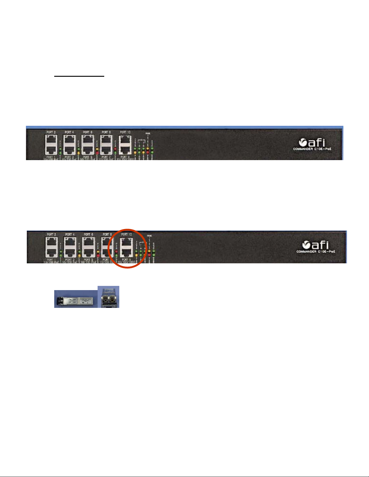
Commander C10 PoE series is available as two model numbers:
C10e-PoE: Is an all copper version and has (8) 10/100 Base T copper Ethernet ports and (2)
10/100/1000 Base T copper Ethernet ports
C10p-PoE: Has (8) 10/100 Base T copper Ethernet ports and (2) open slots for 1000 Base T ports
that use industry standard Small Format Pluggable (SFP) adaptors.
Important Note: C10p versions require optional Small Format Pluggable (SFP) fiber adaptors
into order to operate both 1000 Base T ports. Use only adaptors sold or recommended by
American Fibertek. Use of any other SFP will violate the warranty.
7
Page 8
Operation
Commander is an IP Security Commander’s Center designed for any application that requires
network switching, network traffic monitoring and protecting system components from failure
due to temperature, humidity or the loss of air flow.
Commander’s unique design also provides interfaces for hard
contacts and control of external auxiliary triggers. Commander
Probes are intelligent. They contain a pre-assigned identification
number and are pre-programmed to activate LED # 1 until
reassigned b y an operator. Once programmed for LED and
operations, the programming is maintained within the probe and
will not be lost if the probe is unplugged or transferred to another
Commander.
Records of warning and alarm sensor events are recorded in logs. In addition Commander can be
programmed to poll itself at regular intervals and record its results in a Poll log. Reviewing this
log can help in tracking trends that, while not triggering warning or alarm events might lead to
conditions that significantly affect the life span of mission critical component such as hard drives.
In addition, warnings and alarms triggers as well as logs themselves can be programmed as
emails for alerts and for maintaining logs at remote locations. Commander also provides two
serial communication ports, one for RS 232 and one for RS 485. These ports can be used for data
exchange between Commander and any data storage or data generating source.
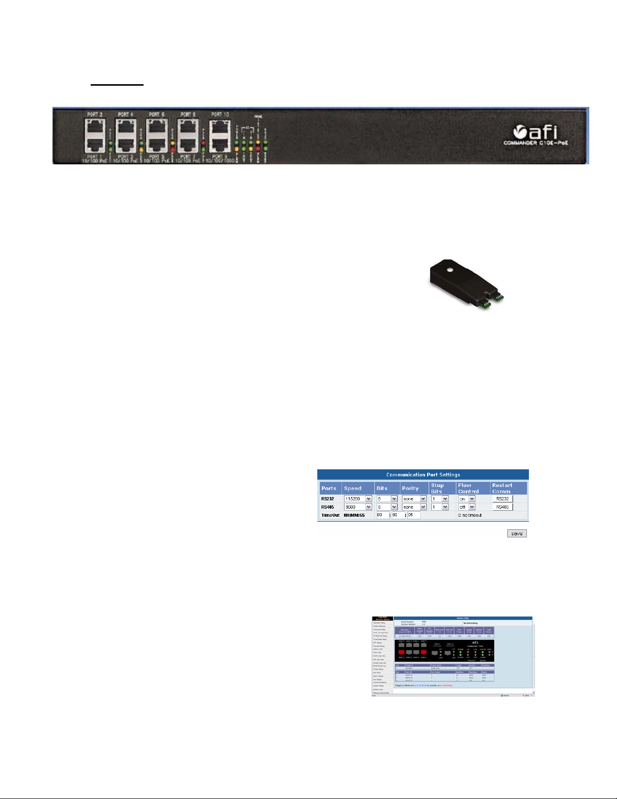
Communication time outs and restarts are
operated in the communication menu. The Time
out settings defines the time duration that if no
traffic is sensed, the port will be shut down. The
port can only be accessed by one client at a time.
If the time is set to 0, no time out will occur and the potential remains for the port to be blocked
from additional clients. Master and Security Admin security levels can set and save time out
settings. All security levels with “Security View” access can manually restart communication
ports by point and click on the selected port .
Commander conditions and operations can be viewed via an
easy to operate User Interface. As Commander is its own
server, no external client software is required. As interfacing
to Commander doesn’t require an Active X component, it
can be viewed and operated with most common web
browsers. The Status view screen displays a series o f colors
matching those on the
front panel.
8
Page 9
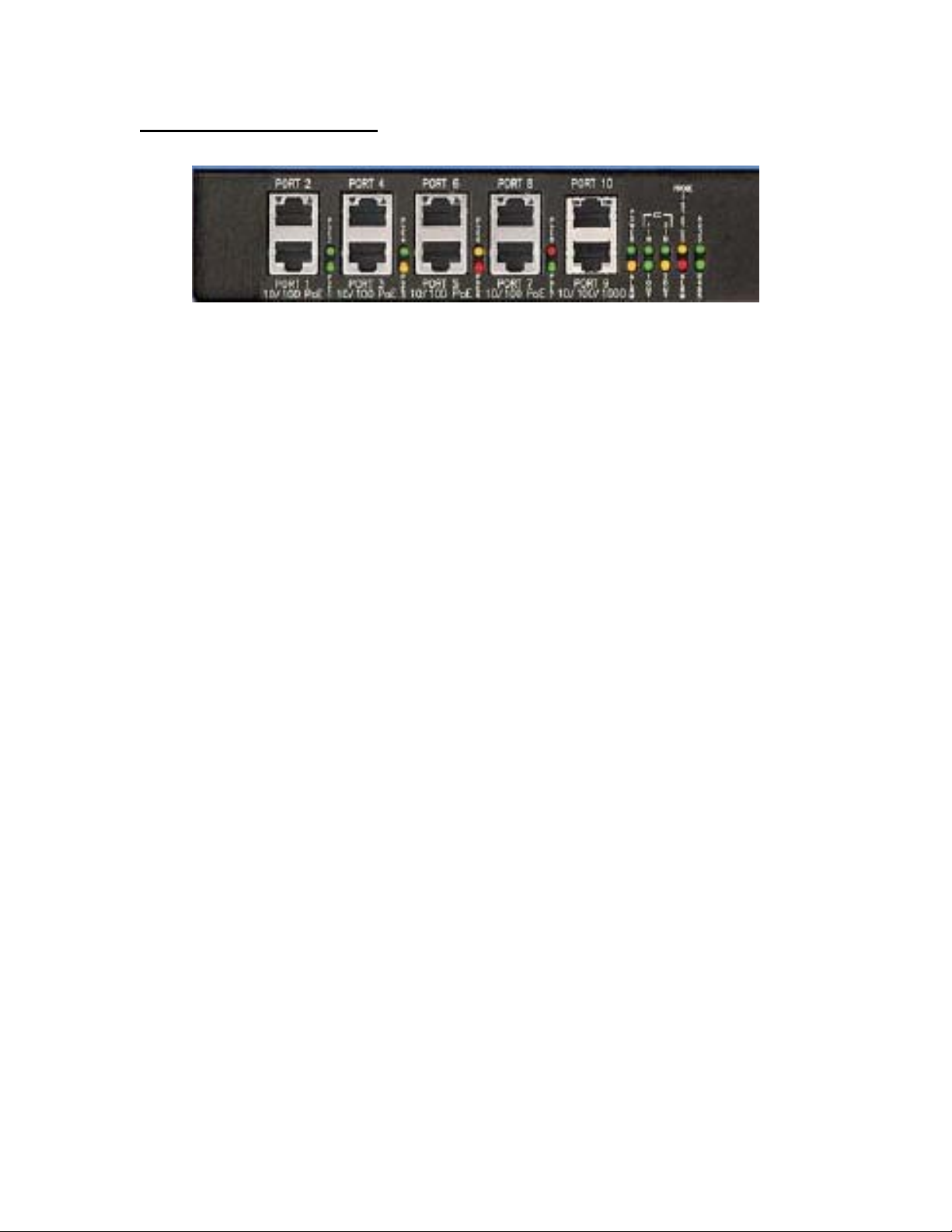
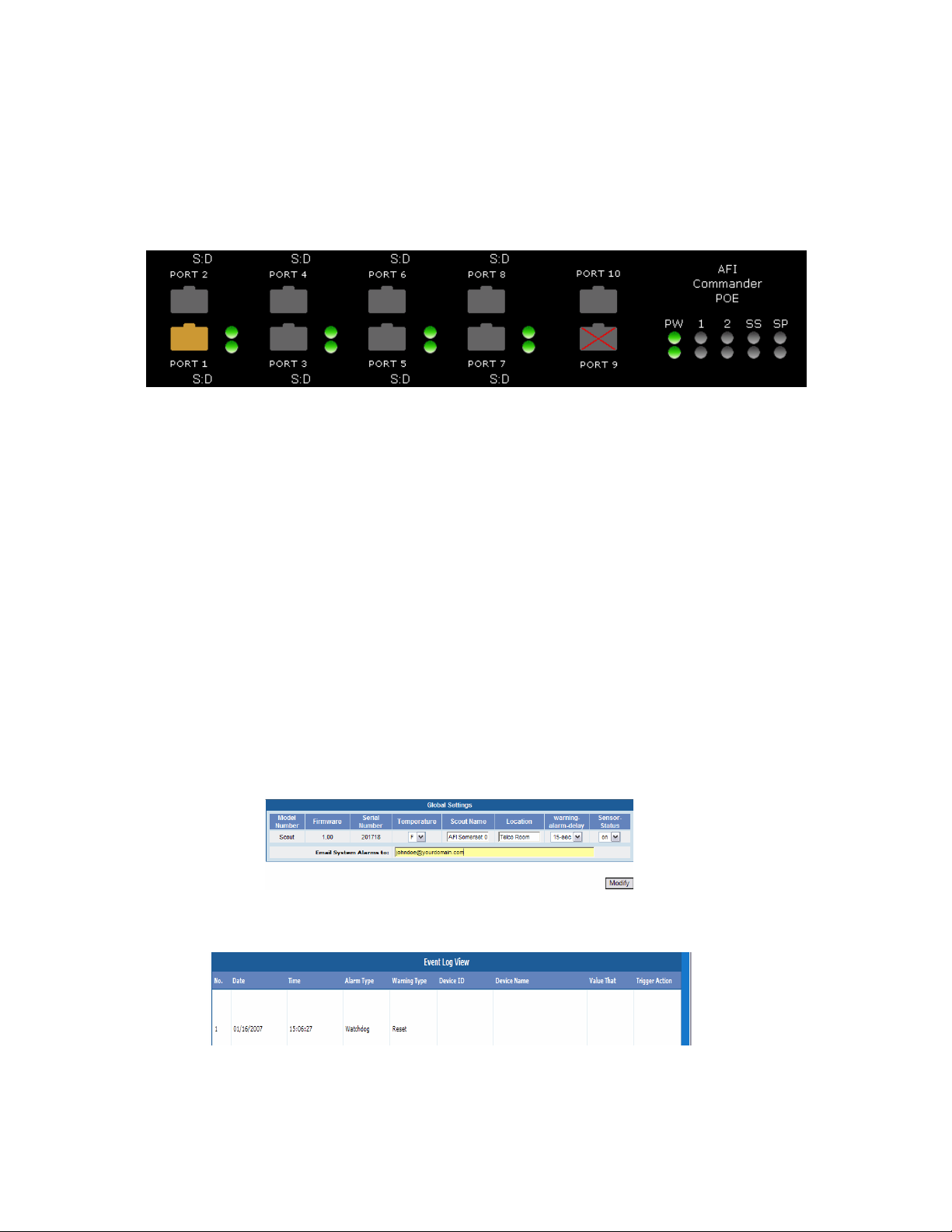
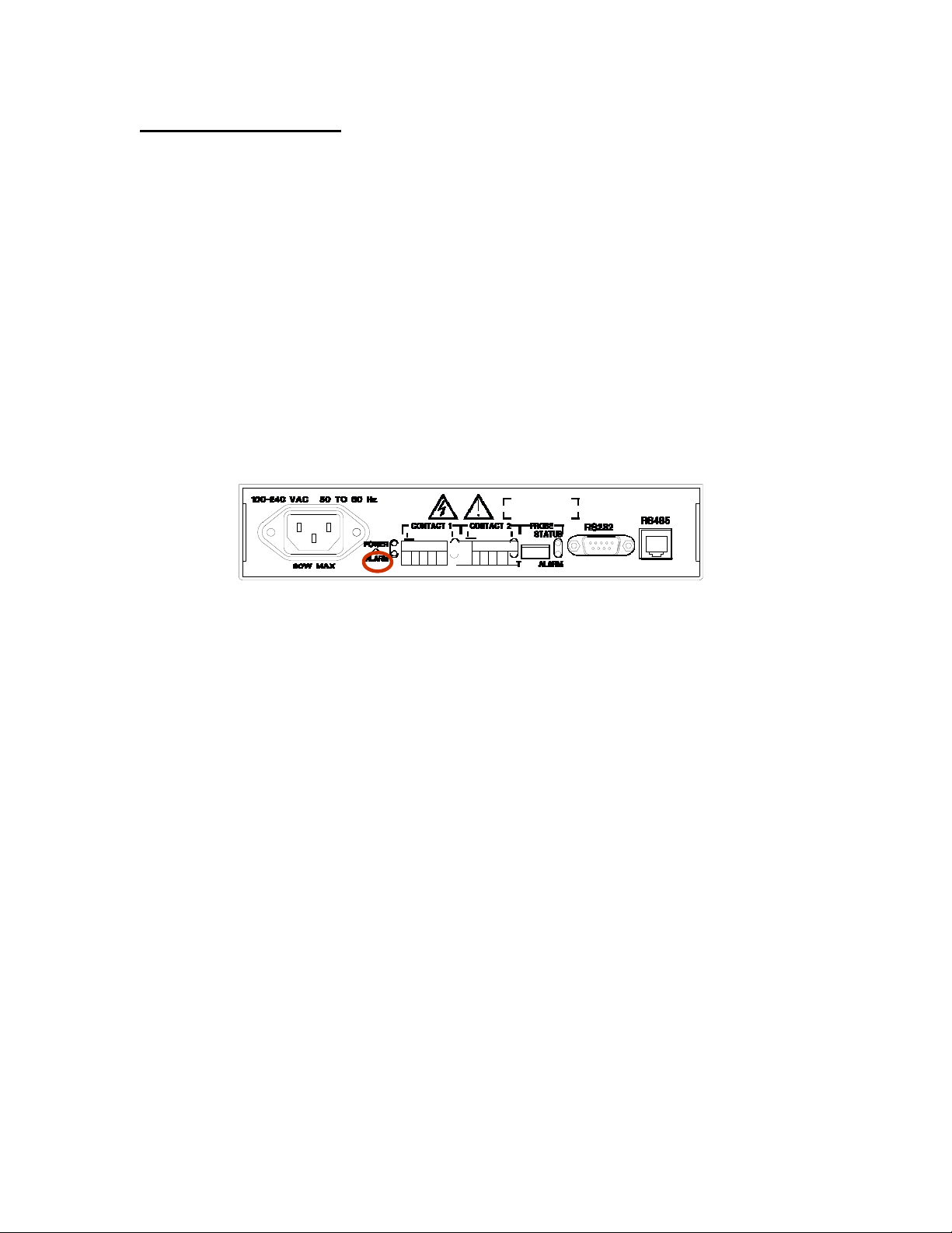
Commander PoE Front Panel
Power: There are two power indicators, one for power supply and one for power status.
The Power LED illuminates green when power is applied.
The Alarm LED is green for normal operation and will turn red for alarm conditions on any of the
internal temperature monitors or power supply voltage monitors.
Solid Green = Norm al Operation
Solid Red = Alarm Condition Present
Flashing Green= Unit booting up
Ports 1 through 8: Port 9 & 10:
10/100baseTx Ethernet Ports: 1000baseT Ethernet Ports:
Link – Off – No connection Link – Off – No connection
Amber - 10 Mb/s Amber - 10 or 100 Mb/s
Green - 100 Mb/s Green - 1000 Mb/s
Act - Off – No data activity Act - Off – No data activity
Amber Flashing – Data activity
Amber Flashing – Data activity
Alarm In 1, 2: The default alarm condition is a closed contact. If the NC check box is active for
an alarm input, then the alarm condition will be an open contact. Alarm contact LED’s are per
“current status”.
Normal condition - Off
Alarm condition - Red
Auxiliary Out 1,2: Auxiliary contact LED’s are per “current status”.
Normal condition - LED is off
Relay Activated - LED will be red
PoE Status
Each port has an associated indicator for PoE status
PoE Off - Led is off PoE On and Normal – Led is green
PoE Searching – Led is amber PoE fault – Led is red
9
Page 10

Data Ports A (RS232) & B (RS485) LEDs:
There is one Bicolor LED per port. (Port A = RS232, Port B = RS485). When the Tx of the port
is active the LED will turn on Red for 0.25 seconds. When the Rx of the port is active the LED
will turn on Green for 0.25 seconds.
Rx: = Data from TCP to Serial
Tx: = Data from Serial to TCP
Probe Status & Alarm LED’s:
Commander operates by sensing the number and location of probes upon power up. Those ports
with sensor probes connected will be indicated on the front panel. Commander has one direct
USB port but can sense up to 4 probes using a USB hub. The Alarm Sensor will reflect the
condition of any of the probes.
If Commander is powered on and a new probe is plugged in, Commander will sense the new
probe and acknowledge its existence. Probes can be installed or removed without having to power
down Commander. When installing or removing probes, perform a browser refresh.
Front panel Sensor Probe S tatus LED States:
No connection, probe is not present - LED is Off
Probe is connected and communicating - LED is Green
Upon connecting a probe for the first time the Probe Status LED will flash Green to Amber four
times.
Front Panel Sensor Probe Alarm LED indications:
No connection, probe is not present - Off
Probe is connected, no alarm has occurred - Green
Probe is connected, warning state activated - Amber
Probe is connected, alarm state activated - Red
The Probe Alarm LED will indicate the active condition for the duration the alarm or warning. In
the event multiple warning and/or alarm conditions are received by the same probe the LED will
alternate between Orange and Red. At the time when the multiple warning and/or alarm
conditions end, the LED will reflect the color of the warning or alarm mode, if any, that is still
active.
Sensor Probe LED:
Front panel Sensor Probe S tatus LED indicates:
No connection - Off
Probe is connected and ready - Green
Probe is connected and communicating - Am ber
Probe is connected but not communicating - Blinking Red
Upon connecting a probe for the first time the Probe LED will
flash Green to Amber 4 times
If the probe is blinking continuously, it indicates that probe could have a problem.
10
Page 11
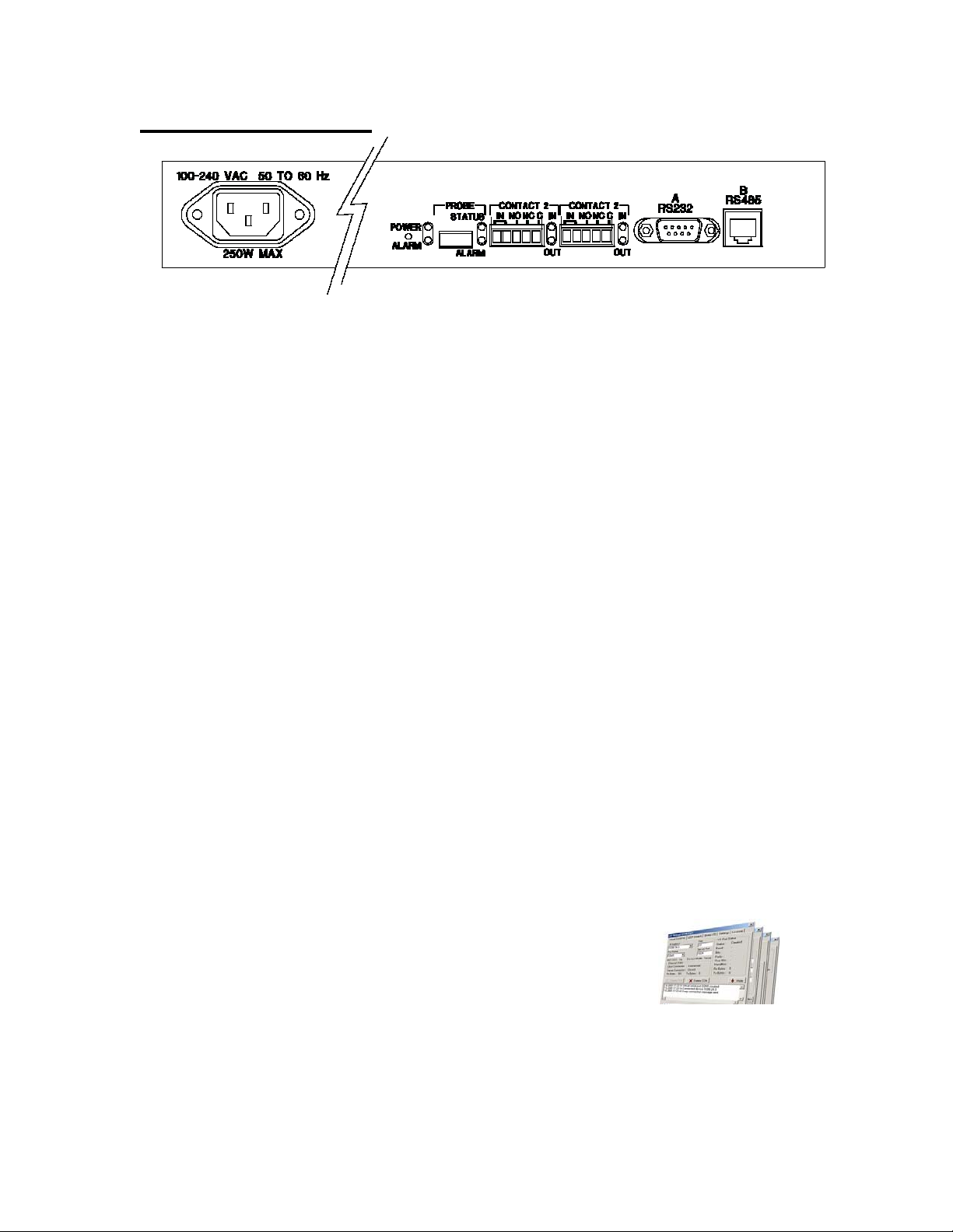
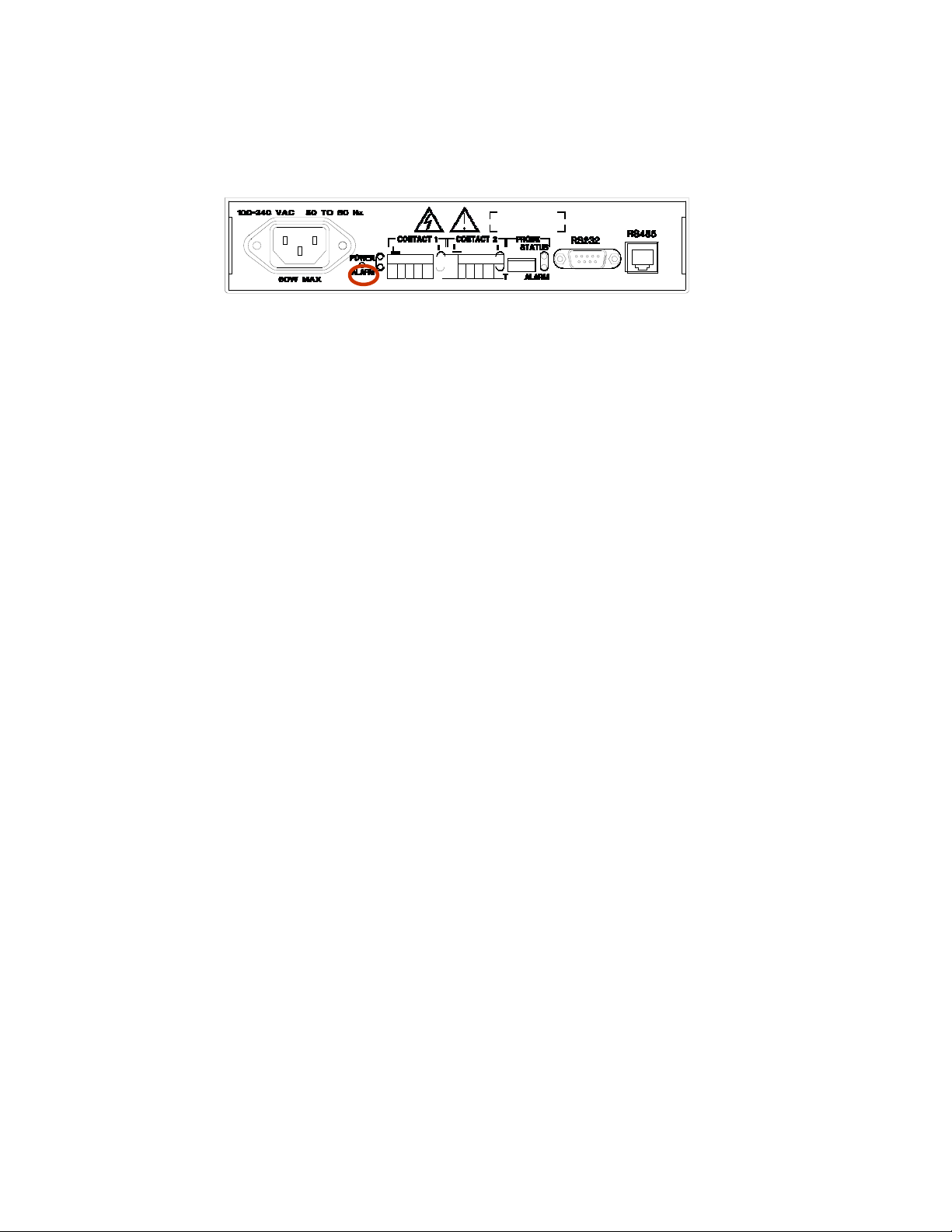
Commander PoE Rear Panel
1 2 3 4 5 6
1. Power connection: 100-240 VAC @ 50 to 60 Hz.
2. Alarm Inputs 1, 2: A potential free contact closure can be used as an alarm input. These
may be programmed as Normally Open or Normally Closed.
3. Auxiliary Outputs 1, 2: This port is triggered by the alarm inputs, sensor warning and
alar
ms as
programmed by the operator. Active durations are also programmable. In
addition Auxiliaries can be manually turned on or off via the web browser interface.
4. Sensor Probe Input: Sensor probes connect directly to the USB ports using a mini to
standard USB cable. Once connected Commander will automatically read the
identification data from the probe and enter it in its data base. Commander can accept up
to 4 sensor probes using a standard USB Hub. It is recommended the hub be self powered
Each USB cable requires a Ferrite RFI reducer is required to meet FCC
compliance standards.
5. Serial Data Port A RS232: A standard DB 9 connector is use for RS 232 bidirectional
communication and can be use to read d ata fro m or transmit data to external devices such
as access control panels and cash registers.
6. Serial Data Port B RS485: The RJ 11 connection is use for bidirectional RS485
communications and can be used to read data from or transmit data to external devices
such as access control panels and cash registers and can be used to control devices such
as PTZ domes
Notes on RS 232 and RS 485:
Both ports are compliant to RFC 2217. In order for a Windows program to recognize these ports,
an RFC2217 compliant driver must b e installed on the computer. A Hardware Serial Port
shareware program is included on the CD supplied with the unit.
AFI Pilot software programs contain RS 232 and RS 485 port
communications as standard features when a Commander is installed
as a device.
Rear panel LEDs mirror the functions of front panel LEDs
11
Page 12
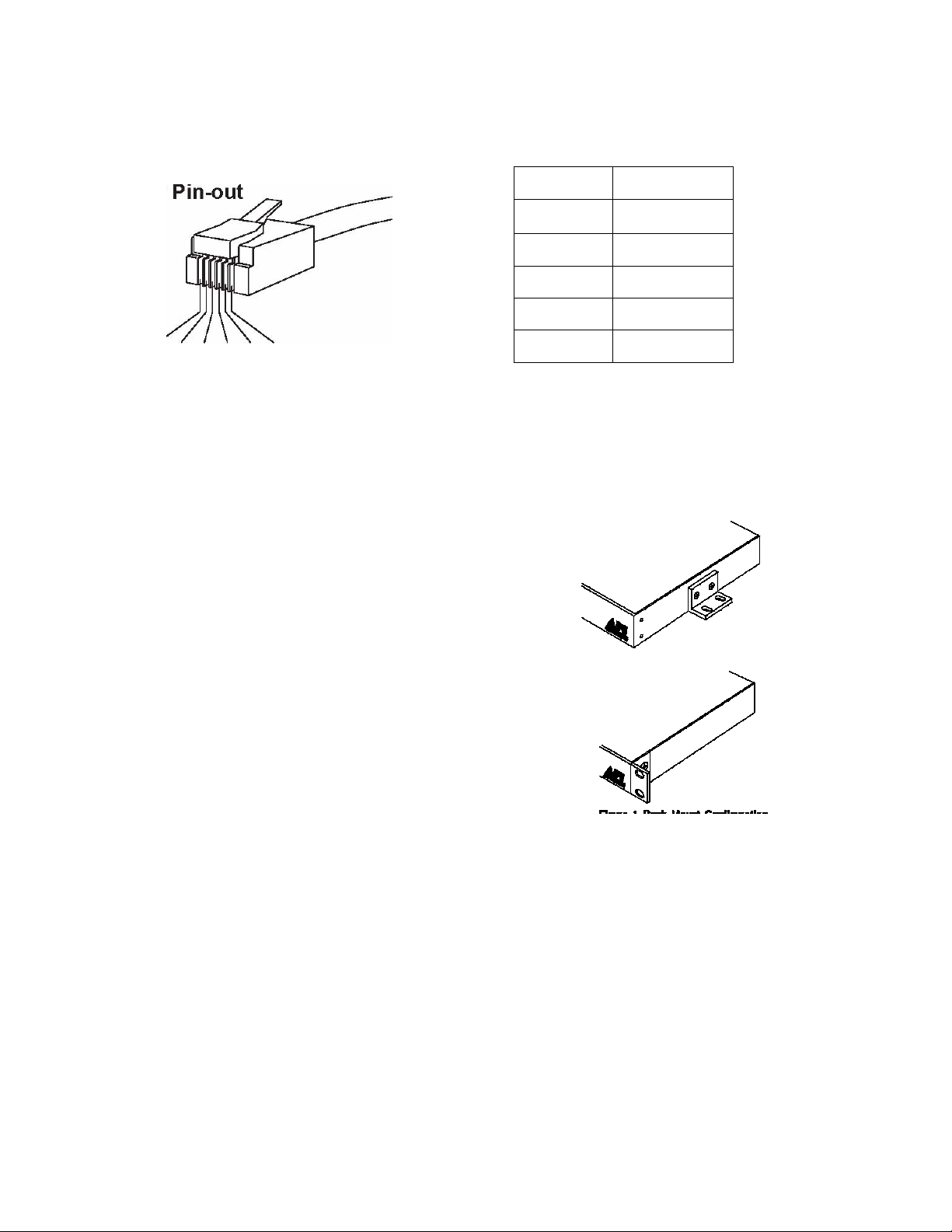
RS485 Connector
The RS232 connections is a standard DB9 DTE configuration
1 - 6
1
Common
2
IN -
3
IN +
4
OUT +
5
OUT -
6
Common
Installation
Mounting
To install the Commander it is first necessary to mount
the rack flanges to the unit. Two mounting flanges are
supplied with each Commander. For flush mounting,
install the ears with the #10 flathead screws provided
There are two rack mounting options. A single
Commander can be installed in a rack using the half
rack mounting kit C10-HRM. Two Commanders may
be rack mounted side by side with a C10-FRM kit.
For rack mounting the ears are installed on the sides of
the unit with the surfaces that have oval holes flush
with the front of the unit as in Figure 1. Mount the ears
with the #10 flathead screws provided. To mount in
the rack cabinet, use mounting screws that are
appropriate for the rack cabinet being used.
Power Source
The internal power supply accepts universal line voltage. Any mains supply from (85 to 264
VAC), (47 to 63 Hz) may be used without modification or adjustment. A universal
connector
is provided on the rear of the unit to facilitate connection to the power mains.
Power Connection
The unit is supplied (in the US and UK only) with a three conductor power cord. The “ground”
conductor is directly connected to the chassis.
power
12
Page 13
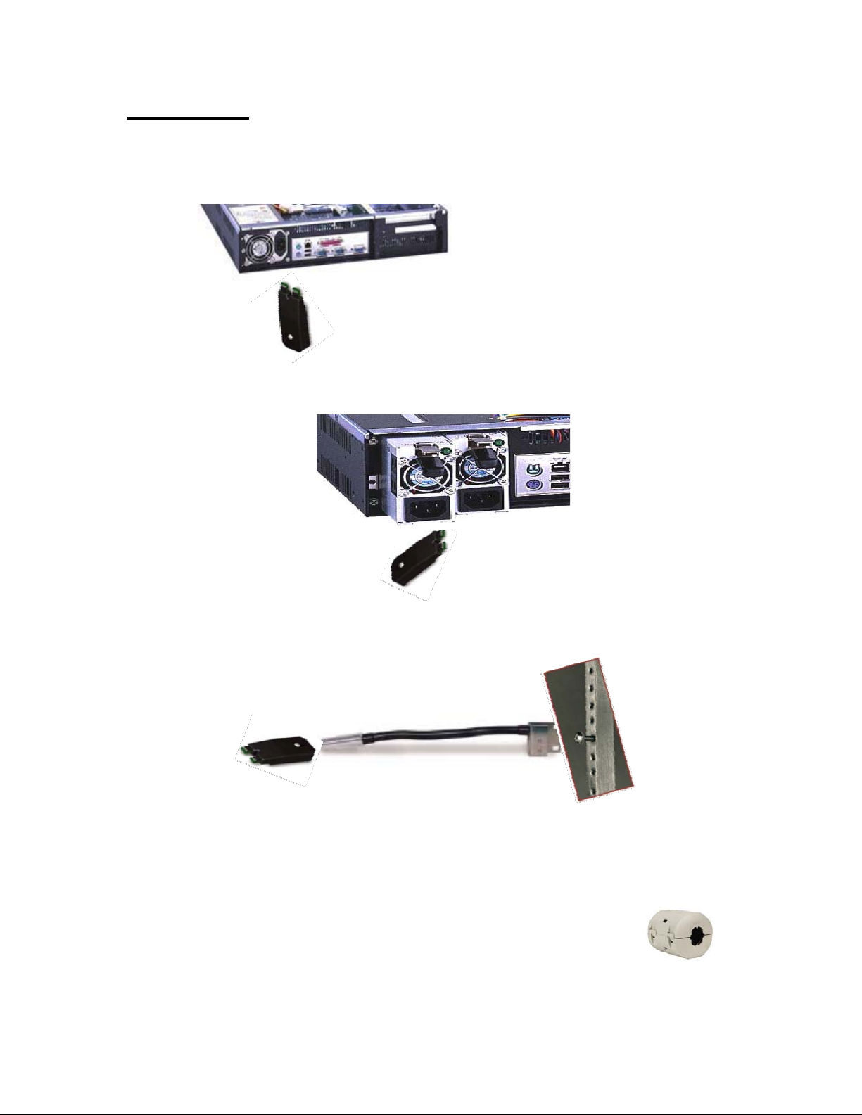
Probe Placement
Temperature and Humidity Reading: (P-TA and P-TAH)
Place the probe between 1-3 inches from the device so that heat will flow directly towards the
sensor. Probes can be directly mounted to a chassis using double sided tape or Velcro.
For Airflow Read
ing:
Place the probe between 1-3 inches from the device so airflow will flow perpendicular to each
sensor tip.
For Rack Mounting:
AFI provides an optional rack mount kit P-RM. Sensor probes plug directly into a goose head
mount providing actual positioning. The P-RM mounts directly to most racks taking up a 1RU
space.
Connecting Environmental Sensing Probes:
Sensor probes are connected to Commander using a standard USB to mini USB cable. When
using the R-RM the Commander probe is directly connected to the mount. The cable is connected
to the rear of the mounting arm. In both cases the maximum distance is 25 feet or 7.6 meters.
In order to comply with FCC radiation requirements, the ferrite clamp
provided with the USB cable must be positioned approximately 2 inches
from the side connected directly to Commander.
Probes can be inserted and removed while Commander is powered on. If an email address has
been programmed in the Global Settings an email alert will be sent.
13
Page 14
Commander’s status can be viewed via LED’s located on Commander’s front panel or via a
Graphic User Interface provided as part of Commander’s web services. As some operators may
also want to view current Sensor probe status and no t just exceptions, a Sensor Status mode is
provided. Using this mode the front panel probe LED’s will indicate status in the same method as
the probe itself. Actual response will be dependent on your network speed.
Alarm Alerts: Watch Dog Timer Operation
Watch Dog Timer:
Commander contains a watch dog timer that will monitor the internal system. In the event
Commander cannot properly operate for more than two minutes, the system will wait until the
condition no longer exists and reboot itself.
Once Commander reboots, all data will have been lost. Many reboot conditions occur due to poor
main power supplies or fluctuations in main line voltage. As with any other computer device, AFI
strongly recommends the use of back up power supply.
Watch Dog Timer Responses:
If the action is due to poor power or power fl uctuations, the Port “B” LED will turn Red
An Email alert “Watch Dog” activated will sent to the address programmed in the Global Settings
when power is returned to Commander. The time will indicate when power was returned.
The first entry in the event log will show as Watchdog with time and date when
conditions
were restored
14
norm
al
Page 15
Web Browsers
Commander does not require an Active X component be loaded on the client computer. As such
Commander is compatible with most web browsers. However, since programming within Web
browsers is not under the control of American Fibertek, the company cannot be held responsible
for the performance of Commander under any given browser.
In addition Graphic User Interface screens and their operation may change from browser to
browser. Their appearance or specific operation may not match the appearance included in this
operation manual.
Commander has been tested with several web browsers; however American Fibertek cannot
account for or be held responsible for changes to web browsers that might affect Commander’s
operation. Internet Explorer and Firefox are the two primary browsers used in the development of
Commander. In some cases even their performance will differ.
In Firefox operation when Commander’s Web page is minimized, the toolbar will change color
on an alert provided Firefox Version 2.0 is used as the browser. Explorer will not perform this
function.
Warning: In order to view a color change to the tool bar (Firefox 2.0 only) and pop up,
Commander must be minimized in the Status View condition, refresh mode and Event Warning
If
enabled.
any of these conditions are not met, no warning will be possible.
15
Page 16
Screen Refresh and Event Warnings
Commander contains a built in web server. No additional software is required to
individual
Commanders. There are two ways to monitor Commander activity.
monitor
Method one is to view a complete .html web page. This allows an operator with the appropriate
permission levels to view different pages and set ups.
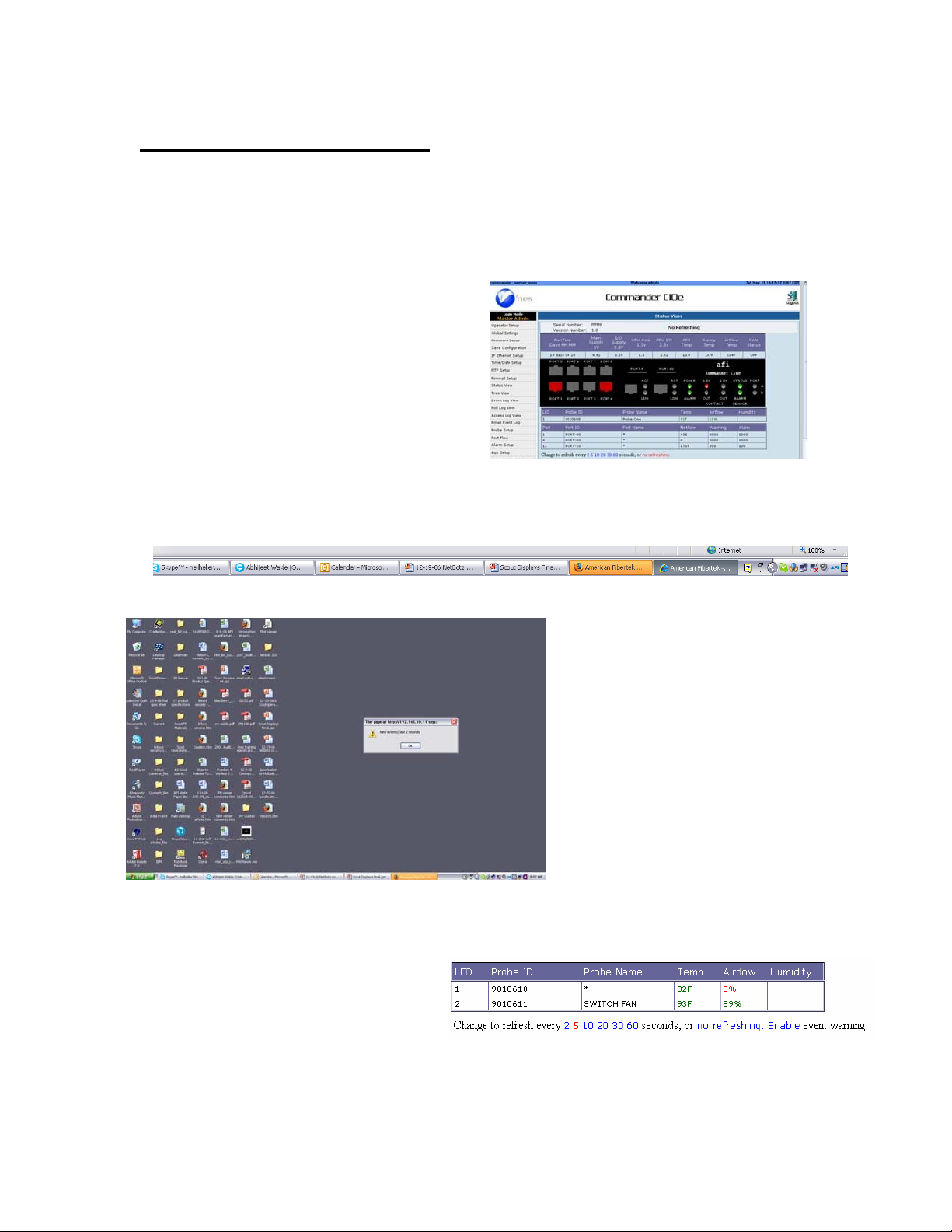
All statuses can be monitored by viewing
Commander’s “Status View” page. Up to 10
Clients can individually monitor an individual
Commander. Clients can have an individual
View and perform individual operations.
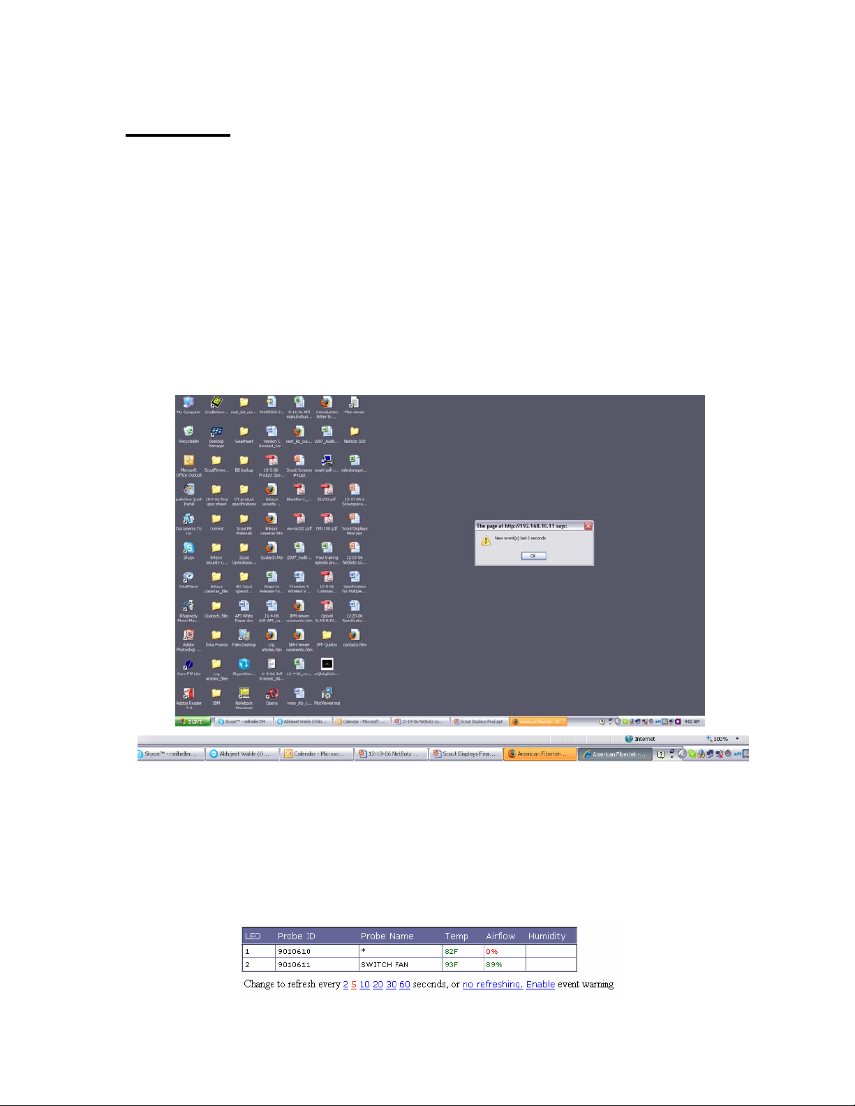
Method two allows the operator to minimize the html page. In this position Commander will be
represented in the tool bar. When warnings or alarms are present the tool bar will turn orange if
the browser is Firefox
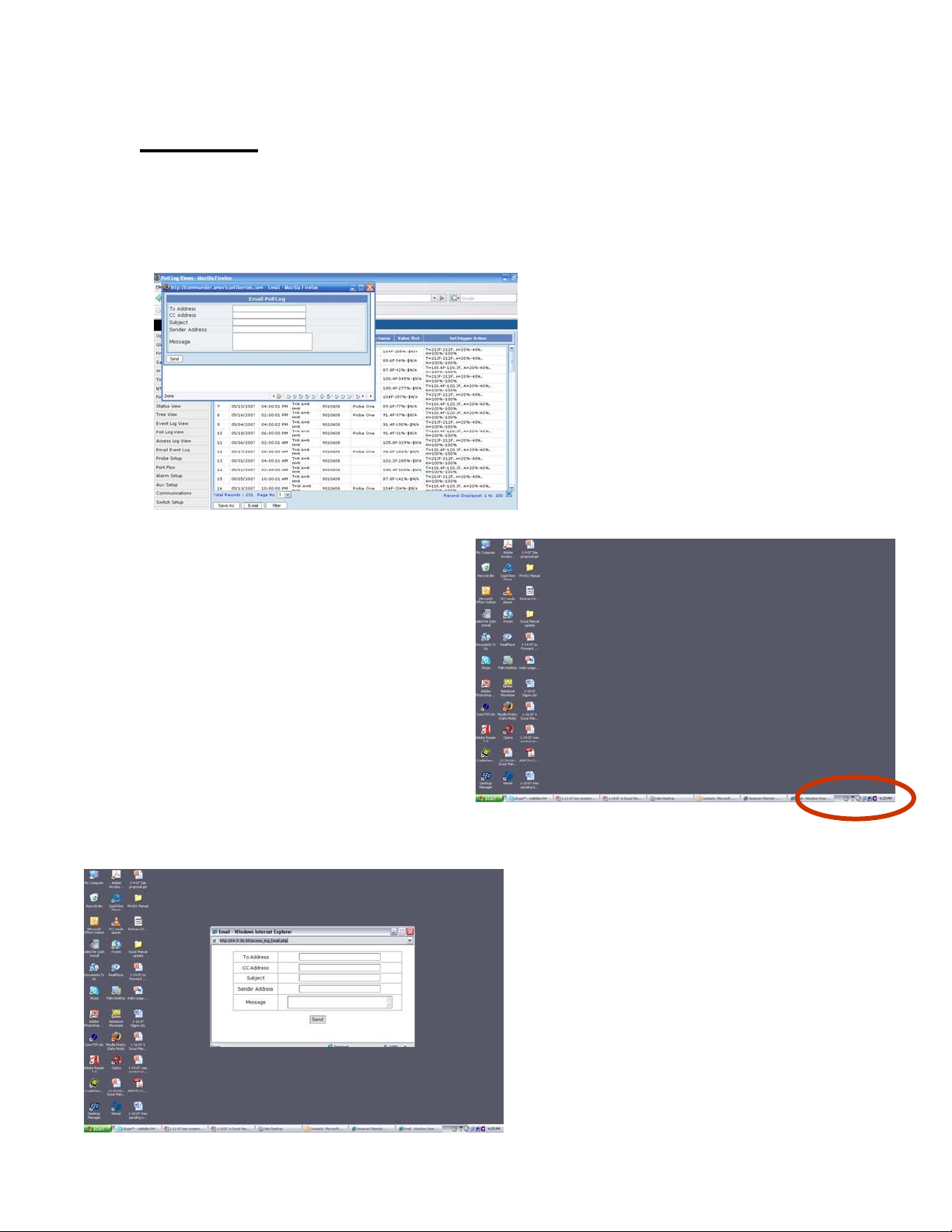
Method two provides a pop up
box which indicates an event has
occurred and the number of events
over a recent period. The operator
can expand the screen to a full
page to view the alarm in more
specific details.
Warning and alert pop ups can be enabled or disabled from the Status View Screen.
Warning: In order to view a color change to the tool bar (Firefox 3.x only) and pop up, the
Commander browser window must be minimized in the Status View condition and must be in the
refresh mode. If either of these conditions are not met, warning pop ups will not be possible
16
Page 17
Event Pop Ups
Many of the functions in Commander operates by means of pop ups. Activating a function in
Commander only requires a single mouse click. If more than one mouse click is used or
additional browser functions are opened the potential exists for the pop ups not to appear the in
screen foreground.
Under normal operations the
pop up will appear in the screen
foreground over the main view.
In all cases the pop up will appear in the
tool bar.
If this occurs click the tool bar
to expose the pop up
17
Page 18
Reset to Factory Defaults
If the Master Admin password is changed and lost for any reason, the only recovery method is to
reset Commander back to its defaults. For this reason the following precautions should be taken:
1. Keep a record of all user names an d passwords. IT and Secu rity user names and
passwords are maintained by and can be accessed by the Master Admin. However the
Master Admin user and password is not.
2. Follow the procedures to download and save programmed settings. If a Co mmander reset
is required all programming will b e returned to its default settings. By saving
programming a Master Admin can perform a Restore, returning Commander to its
programmed functions.
3. Save all existing logs by performing either a Save As to a client computer or by emailing
logs. Please note: once a unit is reset to defau lts or powered down all log information is
erased.
To Reset Commander: Locate the recessed button on the rear panel.
(As a precaution the procedure must be performed during power u p)
!
Power on Commander and wait approximately one minute.
The Port A LED will change to Amber, meaning program is waiting for instruction
Press the reset button for 10 seconds, the Port B LED will turn amber.
Keep pressing the reset button for 2 full seconds longer.
When both Port A and B turn off at the same time the system has reset to its defaults.
This procedure must be followed exactly. If the procedure is not followed as stated, the Port A
LED will turn off after 10 seconds and will not allow any more attempts to reset. To override this
condition Commander must be powered off and on.
Factory Default Settings:
Global Admin Login (Case Sensitive):
User: Admin
Password: Password
IP Address: 192.168.0.246 (Before firmware 20110504: 192.168.10.11)
Net Mask: 255.255.255.0
Gateway: 192.168.0.143 (Before firmware 20110504: 192.168.10.1)
18
Page 19
Resetting Comm ander’s using the RS 232 Port
In some cases it maybe necessary to reset Commander using the RS 232 Port in order to recover
from incorrect IP settings.
!
To reset the RS232 Port:
Connect to the RS232 port with a Null Modem cable.
Set the computer’s terminal program to 115200/8/N/1.
Push the reset button for 4 seconds.
The Port B Led will go Orange when the button is pressed and then Red after the 4 seconds.
The following login will appear:
> AFI Commander Linux
>
> Commander login: root
> Password: (not required)
> Enter the recovery user name
The unit will list the current system time and IP Address with a menu:
>
> Wed Nov 15 15:34:02 EST 2006
> 192.168.10.11 (192.168.0.246)
> >
The settings are as follows:
>
0) Dump current setting
1) Disable Firewall, allow all IPs
2) Set IP to 192.168.10.11 (192.168.0.246)
9) Exit
Select:
Selecting 0 will dump the current status of the Commander device for advanced troubleshooting.
Selecting 1 will disable the firewall until it is set via the web interface.
Selecting 2 will set the IP Address back to the default settings without resetting any other
parameters.
Selecting 9 will set the serial port settings back to default.
19
Page 20
Recovering IP Address when DHCP Is Used
Commander has the ability to be programmed with a fixed IP address and operate in systems
using DHCP. In the latter case Commander’s IP address will change according to the IP address
assigned to it
by
that system’s DHCP server. In order to inform the operator of any such change
in its IP address, Commander will send the new IP to the email address programmed in the Global
Settings.
Please note: The programming of Global Settings is restricted to the Master Admin.
DHCP notification: Commander provides programmable email notification of any IP address
changes. Also, ARP packet with IP and MAC address sent once every minute, may be detected
by using standard freeware such as Wireshark or TCPDUMP. Both methods keep you up to date
on Commanders using DHCP without the need to remove from system or complex external
connections.
20
Page 21

LED Startup Sequence
On power up, Commander will go through a boot process. The front panel LED’s will display
different colors and states as Commander goes through these steps. The following is the normal
sequencing
1) Power LED green: power is applied.
2) The Status LED will alternate between Amber and Green as several boot process occur and
will remain Green when completed:
3) Serial Port A
4) Serial Port B
of these
Kernel is loaded and initialized
Reading real-time clock time
Initializing ramdisk and mounting flash file systems,
Loading the CPU lm85 drivers, and MAC address,
Amber: Ready for reset to factor default.
LED will remain on for 30 seconds to permit reset function.
Off normally. Amber if reset button pressed,
If reset button is pressed longer than two seconds, both Serial Port A and Serial Port B
LED’s will turn off and the system will reset to factor default values.
LED’s after power is applied:
5) The Status LED will alternate between Amber and Green as the boot process continues:
Set up variables including untar web pages, zone files
Setup IP network:
6) The Sensor Status LED will then indicate the final boot steps and will remain off when
complete:
Starting send mail, SSHD, and read probe data.
Mounting NFS if applicable,
Creating new database files and starting database server,
Starting web, ftp, and SNMP servers,
21
Page 22

UTC Time
Time zones, "UT" and "GMT" are indications of "Universal Time" and "Greenwich Mean Time"
respectively and are both semantically identical to "+0000". As Commander can exist on a
network anywhere in the world, it is important to know its time zone location. Please note that
logged dates and times reflect the date and time at the actual location of the Commander and not
at the viewing client.
Sending Email Notices and Files:
At various places in the Commander set up you will be able to input emails addresses for sending
out warnings, alarms, log files, and notices of changes in IP addresses when DHCP is applied.
The
success in
sending out emails is dependent upon your em ail server settings.
If an email is being sent from Commander to an address on the Internet, there are two important
considerations. First your internal network must have a router or gateway to the internet. Second
the
SMTP
server needs to allow the Commander to relay mail or rout the mail to a local user. The
most reliable way is to set up an email account for the Commander.
It is suggested that during the installation of Commander you run a test of all required email
addresses to determine if any problems exist. Ultimately, the solution to these problems will rely
on the programming of your mail server.
Commander has been tested for sending emails to various internet email hosts, however these
providers can change their set ups at any time leading to changes in performance. American
Fibertek does not take responsibility for these changes.
22
Page 23

System
Access
System Access Levels
Commander has three main access levels and seven total login levels. The main access levels are
Master Administrator, IT Administrator, and Security Administrator. The Master Admin can
create
passwords for all IT levels and the Security Admin can create user names and passwords for all
Security levels.
In addition, menus that c onfigure overall operation can only be accessed and set up by the Master
Admin. The separation of IT and Security Administrators allows operations for each to be
isolated
communications without changing or having access to functions affecting security operations and
security directors can make changes to settings affecting security operations without affecting
network communications and operations.
Additional user names and password assignments can be made by the IT Admin which will allow
security users to view, but not change, IT settings. The Security Admin can likewise assign user
names and passwords to IT personnel that will allow them to view, but not change, security
settings.
user names
from
e
ach
and passwords for all levels. The IT Admin can create user names and
other so that an IT administrator can make changes affecting network
23
Page 24
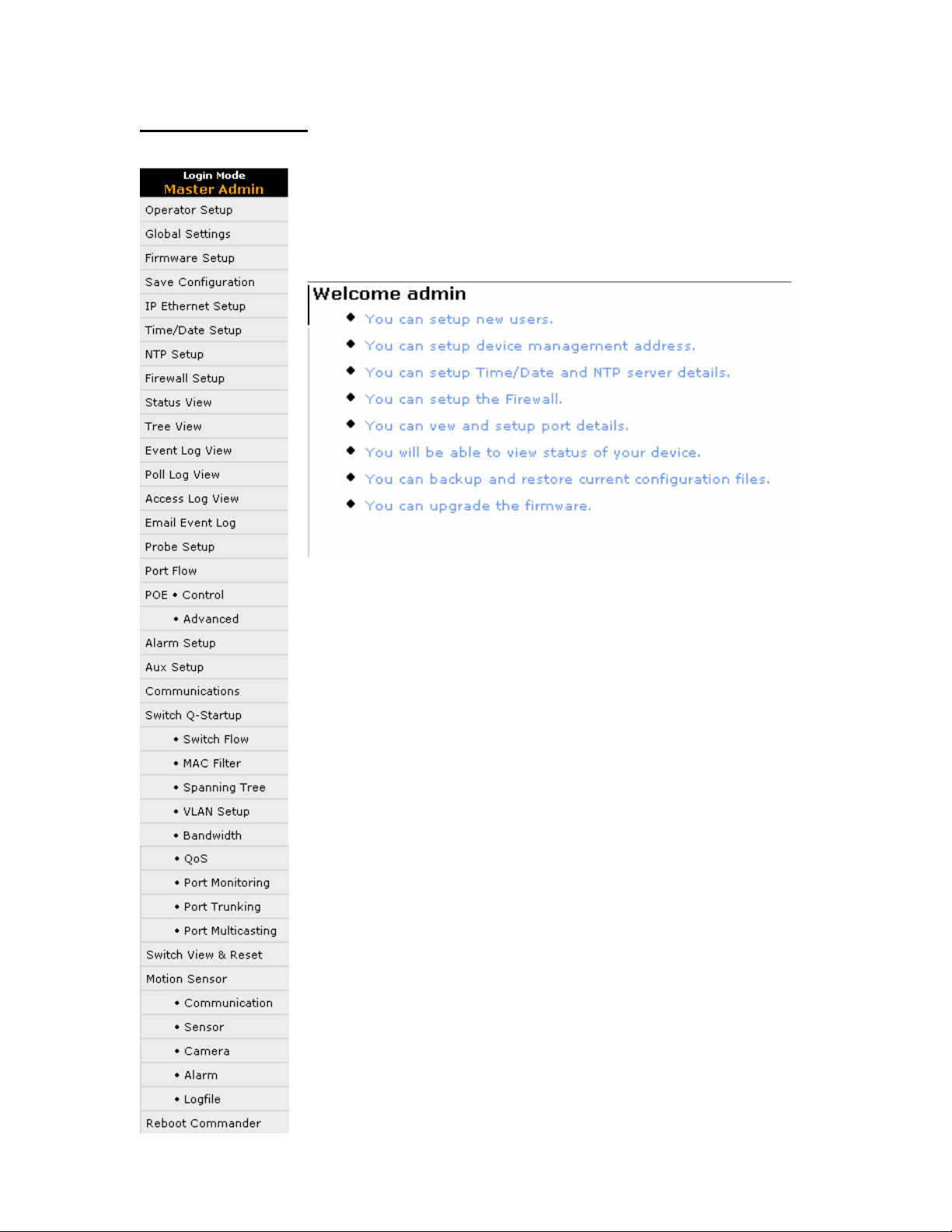
Master Admin Menu
Commander has several modes for operation and set up. All of these can
be found in the operating menu bar which appears on all screens. The
menus available are defined by the access level assig ned to an individual
user. Operator Set Up is restricted to the assigned level access
Each sign in screen contains a “Welcome” message which details the
permissions grated to that access level.
24
Page 25
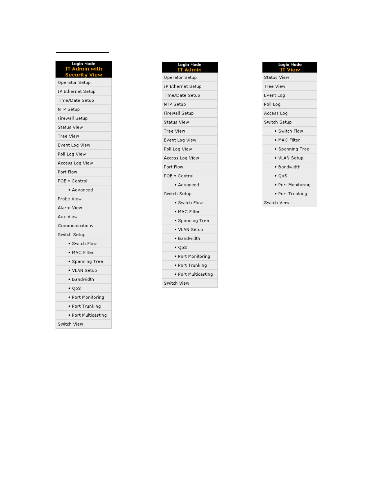
IT Access Levels
25
Page 26

Security Access Levels
26
Page 27
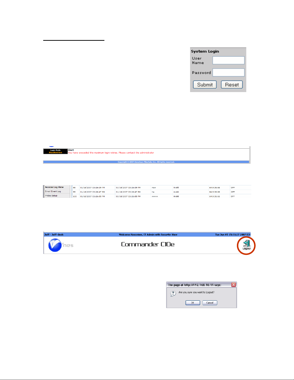
Logging In/ Logging Out
Using a web browser enter the Commander’s IP address (default IP
address in the case of first login) as the URL and the log in screen
will appear. If the location has been previously titled, that name
will
appear.
your
access
name and
Entering the User Name and Password will define
level to the Commander. After entering your user
password,
press Submit. If a mistake is made, press
Reset and reenter the user name and password.
The Master Admin default username is “Admin”. The Master Admin default password is
“Password”. The Master Adm in password should be changed on first login.
Log In Exceeded:
Commander allows three attempts to enter the correct User Name and Password. If on the fourth
attempt the correct name and password are not entered the user will be blocked. Retries can be
attempted after a
5
minute time out period.
When the number of allowable retires is exceeded, the invalid log attem pts will be recorded in the
acce
ss log
showing the date, time and IP address source
Logging Out:
The icon in the upper right hand corner of the screen is used to log out of Commander. Point and
click on the icon to log off. The icon will appear in all operation and programming screens
allowing the log out function at any time.
Auto Logging Out:
If no activity has occurred in twenty (20) minutes, Commander will automatically log out as a
security precaution. To avoid this, after programming is complete, leave Commander operating in
Status View mode with a programmed refresh rate.
As a result of pressing the Log Out icon a pop
up will appear asking if you are sure. Press OK
to log out. Press Cancel to return to the previous
screen.
27
Page 28
Programming
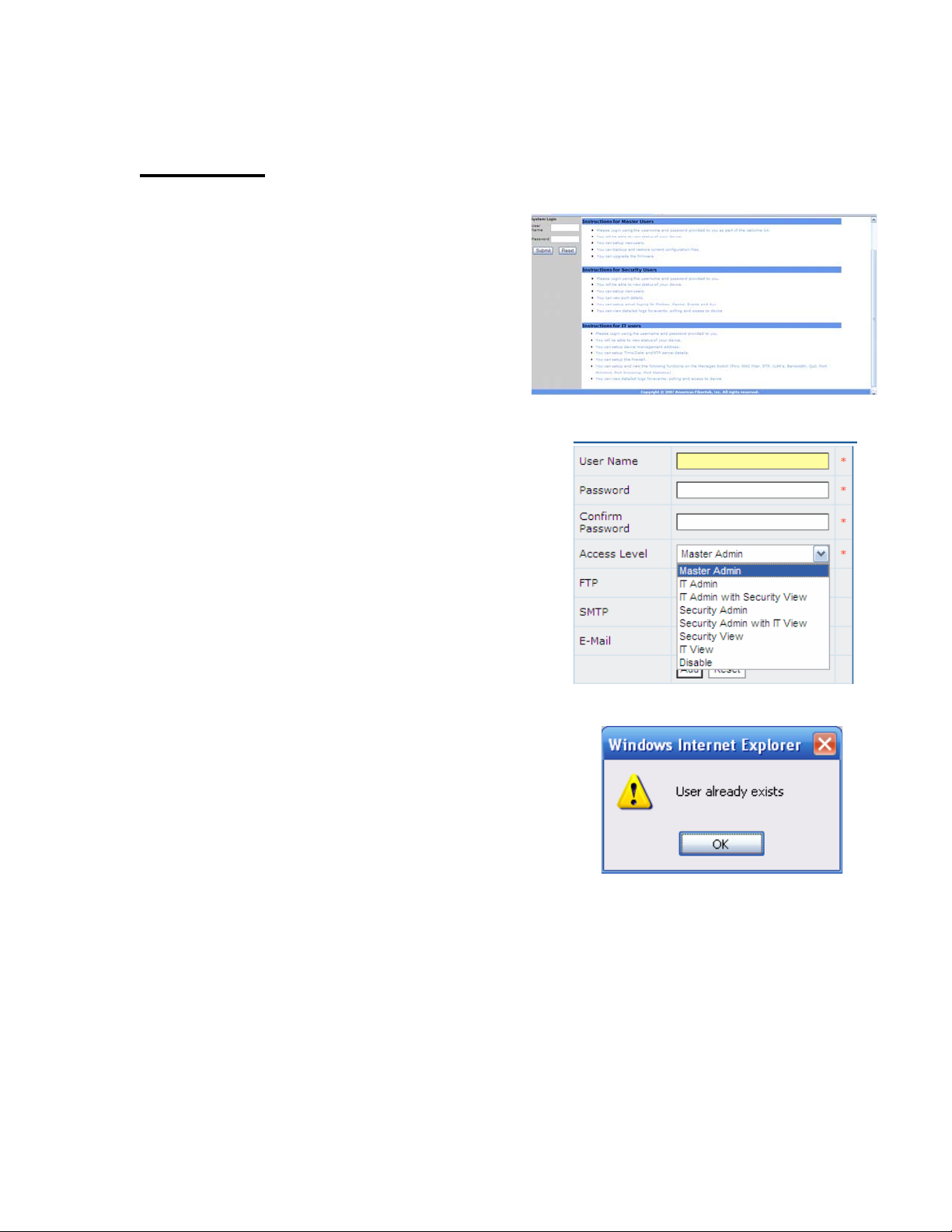
Operator Setup
When first accessing Commander by entering
the correct IP Address, Commander will display
opening screen for entering User Name and
Password. This screen also display the general
permissions for Master Users (Admin), Security
Users and IT Users. Signing in as Master Admin
will display the Master Admin Welcome screen
outlining the general permission levels.
The Master Admin can assign operator user
names and password for all security levels.
Access to operations is determined by the sign in
security level. Only those levels available to the
specific security level will appear in the mode
select.
If a user name and password has previously been
assigned a pop will indicate the “User already
exists”. Click OK and start the process over.
28
Page 29
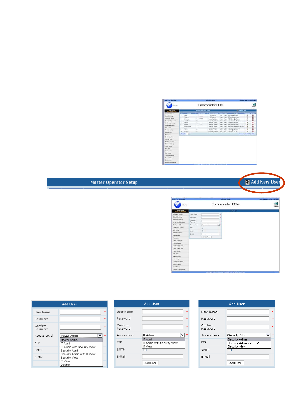
Adding an Operator
Commander allows each of the three Administrators, and seven total security levels. The main
security levels are: Master, IT and Security to assign up to 10 User Names and Passwords for
each category. Assignments can only be made at the authorized level and below. An IT Admin
cannot
and Passwords for any access level.
When entering the Operator Setup mode a
complete list of all User Names and Passwords
allowable at that level will be displayed.
To add a user, point and click on the “Add User” icon
The add user screen will appear. Enter a User
Name, Password, reconfirm the Password
make assignments
in the Master and Security categories. A Master Admin can assign User
User Name is limited to 10 Characters.
Password is limited to 8 Characters .
User and Password assignments will be determined by the Login User Name and Password.
Master Admin IT Admin Security Admin
29
Page 30
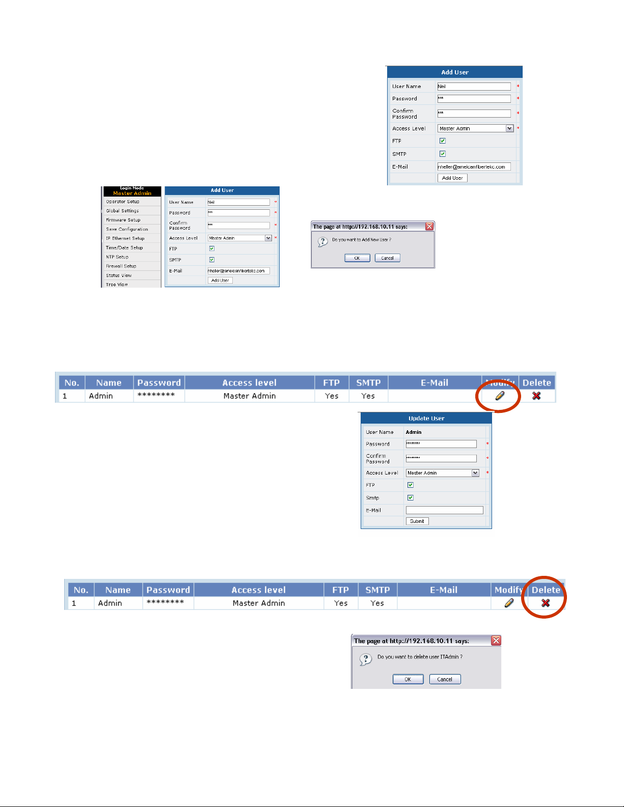
Next Check the FTP and/or SMTP providing
that user permission to FTP and/or Email. Fill in
the
Em
ail address. This will be the specific
email address for that operator. All functions
with email capacity will send their emails to that
address. FTP user name and Password is the
same as the user name and password.
Click the Add User icon and a pop up box will appear asking to confirm your decision. Clicking
OK will complete the process of adding the operator. Clicking Cancel will return to the previous
screen
Operator Set Up-Modifying an Operator
Click on the Modify icon to display the “Update
User” screen. Make any changes as required and
click on the “Submit” button. If the modification
is accepted, the screen will go to the operator set
up.
Operator Set Up-Deleting an Operator
In the Operator Setup click on the “Delete” icon associated with the operator you wish to delete.
A pop box will appear asking you to confirm
your decision. Click OK to delete the operator.
Click on the Cancel button to return to the
previous screen.
30
Page 31

Global Settings
Internal Values and Warnings
Commander monitors its own internal temperature and voltage values. Operating at too high or
too low of these values can r esult in decreasing Commander’ s performance or turning
Commander off. Extreme operating conditions could further result in damaging Commander.
The best precaution against environmental damage to Commander is to properly install and
operate the unit. When mounted in a rack at least 1RU spacing should be provided on both
Commander’s top and bottom. Installations with unstable or questionable power sources should
use back up generators. In all cases the use of filtered power supplies is strongly recommended.
Commander PoE contains two internal fans which are designed to activate at temperatures higher
than
those
that can result in damage to Commander. The use of temperature controlled activation
also contributes to extending fan life as it doesn’t have to operator under proper temperature
conditions.
When these warning levels are reached, Commander will issue email alerts to the address
programmed in Global Settings.
Commander will trigger an internal alarm when any of the following conditions exist:
CPU I/O voltage is less than 2.25 volts or greater than 2.75 volts.
CPU core voltage is less than 1.17 volts or greater than 1.43 volts.
CPU
voltage supply
Main Voltage Supply is less than 4.5 volts or greater than 5.5 volts.
Power Supply tem perature (temp1) is less than -25C or greater than +59C.
Airflow temperature (temp2) is less than -27C or greater than +54C.
CPU temperature (temp3) is less than -16C or greater than +60C.
The internal fan will be turn on when any of the internal temperatures exceed preset limits:
temp1 > 55C or temp2 > 55C or temp3 > 65C
An internal alarm will be issued when any of the internal temperatures exceed preset limits:
temp1 > 60C or temp2 > 60C or temp3 > 70C
These settings are not user adjustable.
is less than 2.97 volts or greater than 3.63 volts.
31
Page 32

Name and Location
Fill in the name and location of your Commander. These names will appear in all logs, emails and
records.
Global Settings: Temperature
Use the drop down menu to select Fahrenheit or
Celsius temperature scale.
Warning-Alarm Delay
Commander probes sample environmental
conditions once every 10 seconds and verify
conditions after 3 samples or 30 seconds.
This
delay is programmable and determines the
duration a condition must be valid prior to
taking any action
Alarm Alerts: To sense an alarm or warning condition a probe is polled three times to avoid any
potential for false alarms. As each poll is 10 seconds the total time to confirm if a condition is
valid is
30 seconds.
To further avoid false alarms the Master Admin can program a WarningAlarm delay which will require the condition be valid for the total programmed time prior to
taking any action.
Global Settings: Sensor Status
This setting is used to display sensor sta tus when
communication occurs between the sensors and
Commander. It is a notification only and its
operation will not affect warning or alarm
reporting. Use the drop menu to select On or
OFF.
Email Address
This email address will receive the following
information:
1. IP address that occur when Commander is operated in the DHCP mode. When the client
receives a notification IP Address has changed, this new IP Address must be entered in the
client web browser.
2. When an existing Sensor has been unplugged or a new Sensor inserted when Commander is
ON.
3. When Commander senses an internal voltage or temperature warning or alarm condition.
You can enter more than one Email address. Multiple email addresses are separated by a space.
32
Page 33

Modify
When the Global Settings changes are
completed, click the Modify button. A pop up
will appear asking you to confirm your choice.
OK will enter the settings. Cancel will return the
screen to the previous mode.
Global Settings: Modify Complete
When Commander has completed the
modification it will issue a Pop Up. Click OK to
complete the process
33
Page 34

Firmware Upgrade
Master Admin Firmware Setup
Clicking on the Mode for Firmware Setup will
display the Firmware Setup screen which allows
new firmware to be loaded updating
Commander. The screen will also show a history
of the most recent updates
Firmware Update Browser Button
Clicking on the Browser button will open up the
Browser located on the client computer. The file
to be
uploaded must be located on the client
computer.
Select the file using the same methods as any
Windows ™ program. The valid file will have a
xxxx.tar.gz. Processing of the file is done by
Commander.
After the file is selected press the Upload button
to start the process.
Wrong File Section
If the file selected is not a .tar file the upload
process will not proceed and the following
display will appear.
Major firmware updates require an ISO CD-ROM i mage be downlo aded from our website
www.amercianfibertek.com
instructions on how to upgrade will be displayed on the laptop after it boots.
. A CD is burned from this image file and used to boot a laptop. The
34
Page 35

File Doesn’t Match
If the upgrade file is not accepted, the following
alert will appear. Clicking OK will return to the
previous screen and allow the selection process
be repeated.
to
Completing the Upload Process
If the correct file is selected a time bar will
appear at the upper end of the screen indicating
the upload is in process.
Successful completion of the Upload will be
indicated by the following alert box.
Master Admin Save Configuration
Clicking on the Save Configuration Mode button
will display the Save/Restore Configuration
screen. This function allows existing
programming on Commander to be saved to a
client computer.
Restore allows programming from a client
to be restored to Commander.
35
Page 36

Save / Restore Configuration
Clicking the Save button will open up the
Windows™ Save As screen on the client
computer.
The operator only needs to select the destination
folder
Save/Restore Feature: Save
If the save button is selected the system will
automatically create the file and downloaded to
the previously selected destination folder.
The .tar extension will automatically be added
after which the operator can elect to change the
file name.
Caution only file names with .tar extensions can
be uploaded.
Save/Restore Feature: Restore: Open File
The Restore process from the previous screen by
selecting Open.
This will open up the Windows™ dialog box.
Select the folder and file name to be restored.
The file will open with the particular file as indicated by its extension. Make certain if the file is a
valid .tar file, the extension is changed prior to uploadi ng
Save/Restore Feature: Restore: Confirmation
After selecting the file, the Restore button will appear along with an alert
box. Responding Ok will active the Restore function and overwrite
Commander’s existing programming. Clicking Cancel, returns to the
previous screen.
36
Page 37

Save/Restore Feature: Restore:
File Restored
When the Restore function is completed the
“File Restored” alert box will appear.
37
Page 38

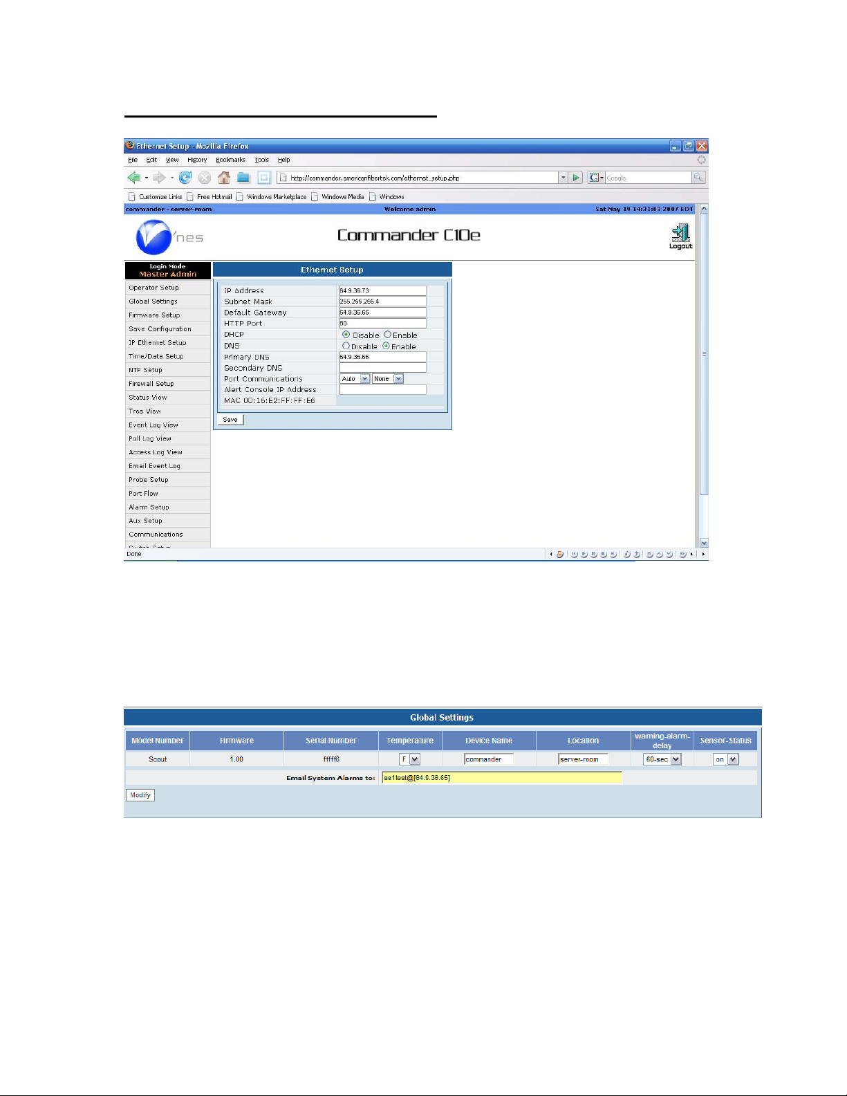
IP Settings
Default IP Settings
Commander’s default settings are displayed to the
right. DHCP is set to off in the default settings and the
default HTTP port is 80.
IP Address: 192.168.10.11
Subnet mask: 255.25.2 55.0
Gateway: 192.168.1.1
HTTP Port
This is the port used to access these setup screens via a
web browser. This setting is restricted to certain ports
as displayed on screen
DHCP
When DHCP is enabled Commander will report any changes in its IP Address to the email
address entered in the Global Settings. (Master Admin function)
DNS
A DNS resolver address is required for SMTP (email) to function. Select Enable and enter at least
one DNS server address.
Port Communications
Port communications is controlled by the switch. See Switch Flow under Switch Setup.
Alert Console IP Address:Port
The Alert Console allows you to program an IP address and port to receive alerts responses to
alarms and warnings. The receiving client computer must allow these alerts to be received. Up to
four addresses and ports may be entered separated by a space.
Network Settings: Saving your settings
Clicking the Save button will result in a pop up
asking you to confirm your settings. Click OK to
confirm. Click Cancel to return to the previous
screen. Remember to make a note of your new
IP Address.
Network Settings: Settings Accepted
When Commander has successfully accepted
your changes it will issue a pop up. Click OK to
continue set up.
38
Page 39

SMTP Settings
Simple Mail Transfer Protocol setup is required
for emails to be sent from the Commander.
There are two methods provided. An internal
SMTP server may be used, or Commander can
connect to a mail server using login account
credentials.
Internal SMPT server will act on its own,
connecting to other mail servers. However,
other servers may not recognize Commander as
a legitimate internet mail server and may refuse
connection. External SMTP server will setup
Commander to act as an email client. This will
require an account on an existing mail server.
Internal SMPT Server
To use the internal mail server, select the “Internal” radio button. Enter the host name for the Commander
to use to identify itself to other mails servers. The values for retry and Duration will set how many times
and for how long Commander will try to send an email before stopping.
External SMPT Server
To use and external mail host, select the “External” radio button. Enter the URL or ip address of the mail
server and optionally the port if not port 25. Some ISPs restrict access to port 25 in order to reduce spam.
Many mail servers provide alternate ports on which to connect. This port would need to be supplied by
your ISP or mail administrator.
Enter the username and password of the account for Commander to use to establish connection. The
default retry is 3, you may enter another value her if necessary.
Email Test Feature
By entering the (To) and (From) addresses in the spaces provide, Commander can send a short test
message using the email setup provided. After entering the information, press the Test button to send. After
a few moments, the Details button may be used to display the SMTP messages in order to aid in
troubleshooting email issues. Knowledge of SMTP transaction messages is helpful.
VPN
The VPN feature will connect to an AFI local device in order to aid in trouble shooting. This is rarely
required.
39
Page 40

Time & Date
The Time/Date function defines the formats for
date and time, the time zone commander is
functioning within, and the current data
and
time. Start by setting the Date and Time Display
Time/Date Setup: NTP Active
Commander’s time reference can be set by NTP
(Network Time Protocol). If NTP is active the
time date setup will have the appearance to the
You
right.
will not be able to set a new time or
date. The screen will indicate “Using NTP
Time and Date Time Zone Function
Time/Date Setup: Selecting Time Zone
Select the time zone using the drop down menu.
Time/Date Setup: Time Zone Map Function
Click on the clock icon to display a world map.
Each dot on the map represents a time zone.
Moving your mouse over the dot will display the
time zone’s name
Click Change to select and accept the time zone
Time/Date Setup: New setting
Press up “Update” to accept the new time
settings. A pop up will appear informing it
will take 30 seconds to process the change.
Click OK to accept. Cancel will return the
screen to the previous setting.
40
Page 41

NTP
Commander provides three different NTP
settings;
None: NTP is not active. Commander’s internal
real time clock is used as the reference. When
using
make certain the time is correct.
the
internal clock as reference, please
Accept NTP Broadcasts: Commander will accept NTP broadcasts. Use this setting if you are
using a system clock.
Poll NTP Server: Commander will Poll a NTP Server at a specific IP address. This setting can be
used to poll at external NTP source located on the Internet.
NTP Setup: Accept NTP Broadcast
If you want Commander to accept NTP Broadcasts, clock the button and Save. A pop up will ask
you to confirm your selection. Click OK to accept and Cancel to return to the previous screen.
NTP Setup: NTP Broadcast Set
Up Successful
If Commander accepts the update, it will issue a
pop up. Click OK to return to the previous
screen
NTP Setup: Poll NTP Server
If you want Commander to Poll an NTP Server,
begin by confirming the location and access to
the server. Enter the NTP IP Server Address.
Next program the duration you want
Commander to poll the time server.
Finish by clicking “Save”.
NTP Setup: Poll NTP Server Setting Saved
If you want Commander to Poll an NTP Server,
begin by confirming the location and access to
the server. Enter the NTP IP Server Address.
Next
Commander to Poll the server. Finish by
clicking Save.
program
the duration you want
NTP Setup: Poll NTP Server Setting Saved
When Commander has ac cepted the changes it
will issue a pop up. Click OK to accept.
41
Page 42

Firewall
Firewall Setup: A-Opening Screen
Firewalls protect Comman der from acc ess from
outside sources that could data access without
authorization.
Firewall Setup: Adding an Address
To add an address, type the address in the “Mask
IP Address” box. Mask subnet addresses are
based on series of numbers 0-32 with 0
representing the full range. Type in the number
that corresponds to your network.
Click “Add” a pop up box will appear asking
you to confirm your settings. Click OK to accept
or Cancel
to return to the previous screen.
Firewall Setup: Adding an Address-Accepted
When Commander accepts your changes, it will
issue
a pop up. Click OK to accept.
Firewall Setup: Adding an AddressRejected
If you input an invalid addr ess a pop will
appear.
Click OK to return to the previous screen.
Firewall Setup: Deleting an Address
To delete an existing Firewall Address, select
the address from address box. Clicking on the
address will highlight it. Click the Delete button.
A pop up will appear asking you to confirm your
selection. Click OK to accept or Cancel to return
to the previous screen.
Firewall Setup: Deleting an Address –Accepted
When Commander has accepted the delete, it will
acknowledge by pop up box. Click OK to
accept.
42
Page 43

Status View
After logging in the screen will automatically go to the Status View. This view allows all users
the ability to see both the Commander’s internal and external status. A description of the
information displayed is as follows:
2
3
1. Header:
1 2
4
A. Access Level as defined by the operator user name and password.
B. Day, month, time, and year with reference time zone. In the header time is
always displayed in 24 hour format regardless of the actual time display setting.
C. Product name and model number.
D. Device name and location as provided by the operator if previously programmed.
2. Log Out:
Clicking the Log Out icon will ask you to confirm your decision and log out. Logging out is
required to properly record the log out time in the access log.
3. Operator Modes:
The modes that appear are determined by the User Name and Access Level provided at log in.
The active mode will be highlighted
4. Serial number and Firmware version number.
43
Page 44

5
5. Internal Settings:
In addition to monitoring external conditions, Commander monitors itself by reporting internal
voltage and temperature conditions. An internal fan will activate as determined by high
temperature conditions avoiding continues operation and extending its usage life span
Internal Triggers:
Commander will trigger an internal alarm when any of the following conditions exist:
CPU I/O voltage is less than 2.25 volts or greater than 2.75 volts.
CPU core voltage is less than 1.17 volts or greater than 1.43 volts.
voltage supply
CPU
Main Voltage Supply is less than 4.5 volts or greater than 5.5 volts.
Power Supply tem perature (temp1) is less than -25C or greater than 59C. (Temperatures greater
than 59C will trigger the internal fan)
Airflow temperature (temp2) is less than -27C or greater than +54C. (Temperatures greater than
54C will trigger the internal fan)
CPU temperature (temp30 is less than -16C or greater than +60C. (Temperatures greater than
60C will trigger the internal fan)
is less than 2.97 volts or greater than 3.63 volts.
44
Page 45

Port Status Color Code:
Green=Normal connection and data flow
Amber=Port is in warning state
Red=Port is in alarm state
Grey with red X =Port is disabled
Alarm LEDS: (Hard Contact Inputs)
Gray or no color for inactive stat
Red in active state (active duration
dependent
upon auxiliary duration setting.)
is
Auxiliary LEDS:
Gray or no color for inactive state Red in
active state (active duration is dependent
upon auxiliary duration setting.
Status LED:
Gray no probe present
Green probe present/normal operation
Alarm LED:
Gray no probe present
Green probe present/normal operation
Amber = Warning
Red = Alarm
In cases when more than on sensor probe is connected using an external USB hub, the Status
LED will flash in sequence representing the status of each of the probes (up to 4) that are
connected.
Power/Alarm LEDs
Power: Green for normal conditions
Alarm: Red for any internal alarm condition
Communication Port LEDs
Port A (RS 232) Green: Tx is active, Red: Rx is Active
Port B (RS 485) Green: Tx is active, Red: Rx is Active
45
Page 46

IP Address conflict notification
In the event the network has a duplicate IP address on the same LAN, Port A will flash
amber as long as the condition exists. Commander will check this network condition each
minute.
When the condition is no longer present the LED will return to the Off state. When
multiple Scouts or Commanders are operating on the same network, all units will show
this condition.
Probe Status
The Probe status view shows (moving from Left to Right)
LED = represents number assigned to that probe from 1 to 4. LED assignments can change due to
operator programming.
Probe ID = is the permanent number assigned to a probe during manufacturing and cannot be
changed.
Probe Name = the name assigned to the probe by the operator
Temp Airflow Humidity = display the current values and status. Warnings will be displayed in
amber and alarms in red. Warning and alarm values are determined by user set up.
Port Status: PortFlow™
This feature reports traffic at each port. Operators can set a traffic levels to meet quality
and reproduction rates for video streams. Warning and alarms can be set to operator
specified levels.
Port=1 to 11. Ports 1 to 10 represent each of the Ethernet ports. Port 11 monitors
Commander’s internal traffic and does not have warning or alarm settings.
Port ID= is the fix port identification assigned to each port.
Port Name: The name assigned to port by the operator during set up:
Port Flow: Display the value of the traffic as packet flow. Amber=Warning, Red =Alarm.
46
Page 47

Port Numbers: Commander’s port numbers are expressed two ways. The physical ports
are identified as Ports 00 through 10. The logical numbering system is Ports 1-11.
Logical Port 11 is Commander’s internal CPU port. This port carries signals from the
Ethernet switch to the internal processor. If communication is lost from this port, the
switch will lose some functions that require the CPU, such as STP, RSTP and
Multicasting. The CPU port is always connected to the same VLAN as logical Port 1.
Status View: Ports
The Status View is divided into 4 sections.
Internal
Conditions
Environmental: Temperature/Airflow/Humidity
Power: Voltage/Frequency/Power
Port Conditions: PortFlow™
and PoE power level.
Status View: Alarms and Auxiliaries
When hard contract alarms or
auxiliaries are active, they will
be displayed in the Status View
Commander can monitor communications with its probes if the Sensor Status is set to on in the
Global Settings. When set to on the LED will display a solid amber color during the
communication process. Please note in the default setting all probes will only address LED # 1
until the programming has been changed. Global settings are a Master Admin function only.
47
Page 48

Refresh Rate
Commander’s status is viewed over the network on a client computer. Changes can only be
viewed when the client’s web page is refreshed. This section allows the operator to select the
refresh rate duration or no refresh at all. The Refresh status is reflected in the Status View’s
header.
Refresh Rate Enabled/Disabled
This selection enables or disables the client’s status view refresh. Refresh must be enabled to
avoid a
20
minute auto log and to see event warnings. If Commander is in the no refresh rate, the
title will be red.
Event Warning Enabled/Disabled
This selection enables or disables the Event Warning feature. It must be enabled in order to pop
ups when the Commander’s Status View is minimized. It is only available in Refresh mode.
Refresh Rate/Event Warning Status Confirmation
This section will confirm the sections made for items 8,9 and 10. If this confirmation does not
the
reflect
desired operation, please change these settings. If the Event warning is off, it will not
appear in this area.
Commander must be in the refresh mode with events warning enabled in order to see pop ups and
display tool bar warnings.
48
Page 49

Front Panel Manual Auxiliary Operation
Commander’s Auxiliary functions can
be controlled from Status View by
clicking on any of the auxiliary buttons.
When an auxiliary button is selected, a pop up will appear asking the operator to confirm the
selection. If OK is selected the auxiliary will become active. If Cancel is selected Commander
will return to the previous screen.
When OK is selected the auxiliary will become active and the auxiliary LED will change from
grey to RED.
If the auxiliary LED is active, clicking on the
auxiliary will cause a pop up to appear asking to
confirm the decision. If OK is selected the
auxiliary will change from On to Off. If Cancel
is selected Commander will return to t
previous
screen.
Warning: Activating or De-activating the
auxiliary function manually will stop the
previously selected refresh rate and pop up and
tool bar (Firefox only) warnings. The screen
status will change to reflect this. When manually
operating the auxiliary function, Refresh must be
re-programmed.
Rules Governing Manual Auxiliary Operation:
(This function is restricted to Master Admin, IT Admin and Security Admin only)
Sensor Operation:
When an auxiliary is activated by a sensor, the auxiliary can be manually turned off as
However;
if this action is taken when the sensor is still in the alarm or warning condition, it will
described.
continue to be logged as active. The “turn off” time of the auxiliary will be logged as the actual
time when the environmental condition is no longer present and not when the operator terminated
the auxiliary. As environmental conditions may last for long durations this features allows
operations to turn off visual or auditable alerts which maybe annoying if left on for long period.
Hard Contact Alarm Operation: Manually terminating the auxiliary will also terminate the
alarm duration. The time of the term ination will be recorded in the Auxiliary log.
h
e
49
Page 50

Activating an Auxiliary
Commander allows an operator to manually
activate an auxiliary.
Move the mouse over an auxiliary in the off
position. Left click will bring up an alert box
asking to confirm your decision to active the
auxiliary. OK will result in activation. Cancel
will return the screen to the previous mode.
Once an auxiliary is active it can be deactivated.
Acknowledgement:
In order for acknowledgement to respond to an
alarm, it must be programmed as part of the
security set up.
AUX operation: If an AUX is active it will
show as red. The user can extinguish the AUX
by point and right click. A pop up box will
appear
Operation of Alarm Acknowledgements and the effect on Aux duration operations:
“Turn Aux
(number) off? Yes/No
In the case of an sensor warning or alarm the following will occur:
The logical device name will turn Amber in the case of a warning
The logical device name will turn Red in the case of an alarm
This action will continue a s long as the conditi on is valid
If an Auxiliary has been programmed to turn on for a pre-determined period of time, its
logical name representation in the tree will become Red, indication it is active.
An operator with permission will have the ability to terminate the auxiliary output prior
to its programmed time, by the action of moving the mouse over the individual Auxiliary
LED and point and click.
A display block will appear with “Turn aux (number) off? YES/NO.
A YES will De-activate the Auxiliary and return that part of the screen to the tree
display. A NO will return that part of the screen of the tree display.
If YES is selected the following actions will take place:
The auxiliary function will be de-activated and will not become activate again until the
current alarm condition is ended and a new alarm input (programmed to correspond with
that individual auxiliary) is received . The Red indication on that Auxiliary’s logical
name will be terminated and return to its normal non-color state.
50
Page 51

Tree View
Tree View shows the status of sensors, alarm i nputs and auxiliary outputs. These are referred to
as “Logical Devices”.
Tree View Operations
When first clicking on the Tree View, the
Device ID will appear. In the Tree, Commander
is referr ed to as the ‘Physical Device” while the
connections to Commander are referred to as
“Logical Devices”
If an operator has previously named
Commander, that name will appear.
Expanding the Tree will show the show the three
logical devices, Probes, Alarms and Aux
(auxiliary)
Expanding each logical device will display its
name, status as indicated by the color,
assignment to an LED and the number of alarms
or warnings that have occurred.
Views: Tree View- Logical Device Status
Sensor Probes: In the example to the right, the
green circle to the left of probe test 03 indicates
it is currently in the normal mode. The (4)
indicates that probe is assigned to front panel
LED number 4. (Although the LED may be
assigned to 1 through 10, Commander only
displays LED #1 in the front panel.) The number
30 indicates that a combination of 30 alarms and
warnings has occurred.
When a name has previously been assigned to a
logical device, the tree will show that name.
When a name has not been assigned it will
automatically be given the probe ID number.
Port Probes: Are displayed under Probes. The
number in ( ) is the port number displayed after
the Port Name. The number following this is the
number of events that will appear in the
when
active.
log
51
Page 52

Aux (Auxiliary): The indicator to the left indicates the alarm status, Gray for OFF, and Red when
in the active alarm mode. The alarm mode will be displayed for its programmed duration or until
the operator terminates by using the front panel status. The operator may provide a name for each.
OFF indicates the alarm is not currently active. The first number indicates the number of times an
OFF to ON state transition has occurred while the second indicates the number of times an ON to
OFF has occurred.
Logs
To display the history of a logical device, point
and click on a device in the tree display. Its
history will be displayed. Sensors will also
display their programmed alar m and warning
levels.
the tree. To
logical device,
The + sign indicates when an event started and
the
Clicking on
–
signs shows when it ended.
a logical device will collapse
view the
repeat the
tree or to select another
previous process.
52
Page 53

Log Database
Commander maintains a database of events. Poll and Event Logs can hold as many as 30,000
entries in the following maximum storage configurations:
Sensor Probes: 1,000 entries per sensor probe (4 probes = 4,000 entries)
Ethernet Ports: 1,000 entries per port (10 ports = 10,000 entries)
Alarms: 1,000 entries
Auxiliary: 1,000 entries
Event Log: 16,00 0
Poll Log: 14,000
Access: 1,000
Event Log
The Event Log Displays events in the form of
Sensor Alarms, Warnings, hard contact alarms
and auxiliary activity as programmed by the
operator. The log displays the Date, Time, Type,
Logical Device ID and Name, the trigger value
that was assigned (in the case of sensors) and the
action that caused the trigger to occur.
+ indicates time event started
- indicates time event ended
Poll Log
Poll log entries occur based on the operator programming. Only Sensors are polled. When the
poll
occurs
the time, date Sensor ID, Name, and current temperature, airflow and humidity are
along
recorded
with there operator programmed trigger values.
Access Log
Access log entries occur based upon users logging in and out of the Commander web browser. In
order to properly register the time an operator has logged off in the Access Log, the operator must
log out and not end the browser session. Failure to log out first will cause an error in the Access
Log mode which can interfere with data filter functions.
For Event, Poll and Access Views:
Use the drop down menu to select an
page
For Event, Poll and Access Views:
You can view up to 100 entries at a time by
using the increase or decrease arrows
individual
53
Page 54

Event & Polling Logs
The Event log will display the time the Auxiliary was activated and the time the Auxiliary was
de-activated which will be the time the operator selected this function.
With regard to Sensor Alarm functions: (applies only to sensor events)
The termination of t he Auxiliary function will not affect the Alarm duration of a sensor event
The alarm will remain active for the duration of that the alarm condition.
The alarm logical name in the tree will remain Red as along as the Alarm condition is valid.
The Event Log will show the time the Alarm condition started and the time the time the Alarm
condition ended.
It will NOT correspond to any user action taken with regard to de-activating the auxiliary
function.
With regard to Warning Functions: (applies only to sensor events)
The termination of the Auxiliary function will not affect the Warning duration.
The Warning will remain activate for the duration of that Warning condition. The Warning
logical name in the tree will remain Yellow as along as the Warning condition is valid. The Event
Log will show the time the Warning condition started and the time the time the Warning
condition ended.
It will NOT correspond to any user action taken with regard to de-activating the auxiliary
function. In the case of a Hard Contact Alarm:
The logical device name will turn Red in the case of an alarm.
This action will continue as long as the condition is valid
As the programmed Alarm action may be a short duration pulse, the duration of the alarm a ction
will be determined by the duration of the programmed auxiliar y.
If the operator has not programmed an auxiliary duration, the logical device name will flash red
once.
The
operation manual will caution the operator that an auxiliary duration should be
programmed for this function.
If an Auxiliary associated with the hard contact alarm has been programmed to turn on for a predetermined period of time, its logical name representation in the tree will become Red (indicating
it is active).
Both the alarm input and associated auxiliary logical device names will be Red, indicating they
are activate.
An operator with permission will have the ability to terminate the auxiliary output prior to its
programmed time, by the action of moving the mouse over the individual Auxiliary and point and
right click. When the point and click action occurs the following will take place. Both the Alarm
and Auxiliary logical device names will change from Red to no color indicating they are no
longer active The Event log will reflect the point and click as the termination time for both the
Alarm and Auxiliary action.
54
Page 55

Deleting Event and Poll Logs
Tree View provides three operations. They are:
Save
as: This will save the complete log.
Email: This will email the complete log.
Delete: This will delete any individual entry or
the complete log.
When the number of entries exceeds the screen view use the slider to view additional
entries.
Event and Polling Logs View
The Event, Poll and Acces s Logs use two
different methods for viewing all entries when
they exceed a single page. The total number of
records
number column. The total number of record s
displayed is shown under the values column.
is
displayed at the bottom of the item
55
Page 56

Saving Event and Polling Logs
Clicking on the “Save As” button will open up a
pop up asking to confirm your choice. Click OK
to
save or
the previous function.
Requesting a Save As function will result either
a request to save or open file depending on the
type of browser used.
Clicking the Email button will open up the
Email address box. Fill in a primary email
address and if required a CC or secondary
address. Indicate the subject, the sender address
(your email address). A custom message can
also be included.
Press the Send button to
Cancel which will return the screen to
email
the Log
For a successful email delivery , DNS, gateway and email server setting are crucial. Co mmander
can deliver email over Intranet or Internet connections, to any reachable SMTP server. However
some SMTP servers may reject the email. It is the responsibility of the operator to make certain
Commander emails are not rejected by the SMTP server.
56
Page 57

Email and Save As File Format
When saved the format will display the log it was created from, the date and time. The last four
digital represent the time expressed in military time. In the example below the Access Log was
saved at 15:15 or 3:15 PM.
AccessLog_28Nov06_1515.csv
EventLog_28Nov06_1426.csv
PollLog_28Nov06_1701.csv
Commander provides individual email messages for all warning, alarm and log transmission
functions. Emails are sent according to user based programming for times, alarms and warning
settings.
Environmental Sensor Emails
Sat, 2 Jun 2007 00:26:20 -0400
commander commander-server-room
ProbeID=9010608
ProbeName=Probe One
Temp Warning Temp Current=100F, Warning=100F, Alarm=120F
AirFlow Current=180%, Warning=20%, Alarm=40%
Humidity Current=$N/A, Warning=100%, Alarm=100%
Ethernet Port Emails
Tue, 5 Jun 2007 10:04:30 -0400 commander Jeff-Jeff-desk Network=PORT-00
PortName= PortFlow Warning –
PortFlow Current=6808, Warning=3000, Alarm=1000
Port Connect Emails
Mon, 4 Jun 2007 14:20:51 -0400 comm ander Jeff
PORT-05 Connected
Port Disconnect Emails
Mon, 4 Jun 2007 12:45:01 -0400 comm ander Jeff
PORT-05 Disconnected
Port Disconnect Emails
Mon, 4 Jun 2007 12:45:01 -0400 comm ander Jeff
PORT-05 Disconnected
Alarm De-activation Email
Tue, 5 Jun 2007 12:26:21 -0400 commander Jeff 192.168.0.247
alarm2_name IN[2]ON->OFF.
alarm1 IN[1]ON->OFF.
57
Page 58

Auxiliary Activation Emails
Tue, 5 Jun 2007 12:26:27 -0400 commander Jeff 192.168.0.247
aux2_name OUT[2]OFF->ON.
aux1_name OUT[1]OFF->ON.
Internal Status Emails
temp1=<1.00 -1.00 42.50> Current=42.500000 Threshold=>40.000 000 Alarm temp3=<1.00 -
1.00 -127.50> Current=-127.500000 Threshold=<-16.000000 Alarm
# in0: CPU I/O voltage (not scaled)
# in1: CPU core voltage (not scaled)
# in2: 3.3V nominal (not scaled) # in3: 5.0V nominal (scaled)
# temp1: power supply temperature # temp2: airflow tem perature
# temp3: CPU temperature
# fan: side fan
Notification of Log Transmission
ss1_event_log_commander.csv, ss1_poll_log_commander.csv, ss1_access_log_commander.csv
Log files from IP:192.168.10.11
EventLog Fri Jun 1 13:0 0:3 6 EDT 20 07 device_nam e=commander
Log Filter Functions: How it Works. Time and Date
The Event, Poll and Access logs have filter
functions which allows an operator to search for
results based on specific conditions. To enter
Filter mode, point and click on the Sort
the
58
Page 59

Log Filtering
The sort function is divided into Four Major
They
are:
1. Start Time and Date/End Time and Date
2. Probe
3. Contact
4. Auxiliary
Port Filter functions are found under probes
areas.
Time and Date:
Click the Calendar next to the start date and
select the starting date from the calendar. Enter
the time and repeat the process for the End Time
and Date. The time is entered as Hours: Minutes:
Seconds. For time settings use the drop down
menu to select AM or PM
If an incorrect date is selected a Pop Up will
appear. Click “OK” to re turn to th e previous
screen. Re-enter the correct date.
Selecting Probes and Ports
Commanders Filter function allows the operator
to select up to three probes by point and click
activate a dr op down menu. The probes are
displayed with their name, or if not named as
their probe ID.
If more than one probe is select the sort function
will OR the probes providing results for each of
the selected probes. Click to make a selection.
to
59
Page 60

Selecting Warning and Alarm Types
Commander offers a choice of two different
Warning and Alarm types. Each provides a drop
down menu for selecting Temperature, Airflow
or Humidity.
If more than one Warning or Alarm Type is
selected, the Filter function will “or” the
selections.
The conditions will define the probe. If two
probes are selected along with Temperature
Warning, Airflow Warning, Humidity Alarm
and Temperature Alarm, the Filter will show
results if anyone of the selected conditions is
true for anyone of the selected probes.
Click to make a selection
Selecting Alarm Contacts
Commander provides searching for one external
alarm contact. Click the drop down menu to
display the alarms, which are shown with there
assigned names or default name is none has been
assigned. Click to select the alarm contact.
The selected search result will AND the Alarm
Contact with the probes you have previously
defined. A positive search result requires that
BOTH the defined or conditions for the
AND
the defined alarm contact must be true.
probes
Selecting Auxiliary Outputs
Commander provides selecting one auxiliary
output. Click the drop down menu to display the
auxiliary, which are shown with there assigned
names or default name if none has been
assigned. Click to select the alarm auxiliary
output.
The selected search result will PLUS the
Auxiliary Output with the probes you have
previously defined. A positive search result
requires that BOTH the defined or conditions for
the probes PLUS the defined auxiliary output
must be true.
60
Page 61

No Search Results
If the search yields no results and “No Records
Found” pop will appear. Click OK to return to
the previous screen and recheck the data y ou
entered.
Closing Filter: Close sorts by activating any other function.
Important: Filter results will not be saved unless a “Save As” or “Email” action has taken place.
Exiting to another function or starting another sort will automatically delete the sort results.
Deleting Logs
The ability to delete whole logs or any individual item within a log is only be available if the
operator is signed in as the Master Admin. The process will not be available at any other
operator level except Master Admin. The delete function can only be performed in a tree view
and will apply to any tree view. This delete function is not to be confused with the action that
takes place when an operator other than the master admin has performed a sort and search
function. The Master Admin can apply the Delete procedure to the search results log.
The “Delete” button will NOT appear in the tree
view screen if the operator has NOT signed in as
the
Master
Admin.
To delete the complete log select the top delete
check box. All items in the log will be
highlighted.
Next click the delete button.
To delete and individual item, select that item’s
check box. Next click the delete button. Repeat
this action selecting all individual items to be
deleted prior to pressing the Delete button.
Confirming Delete:
After all individual log items have been selected
press
the Delete button. An alert box will
appear. Selecting OK will permanently delete
the selected items.
Selecting OK will permanently delete the
selected items.
Selecting Cancel will cancel the action and
return to the previous screen. The select items
will still remain as selected.
61
Page 62

De-Selecting an Item To be Deleted
To deselect an individual log entry, the entry
must first have to have been selected and
highlighted. Move the curser over the check box
and left click. The highlight will return to a
normal state.
62
Page 63

Access Log
Note: Access Log is only accessible to Master
Admin and IT Admin users.
The access log displays the date/time, the name
and access level of the person that signed on in
addition to the Client IP address. The log also
indicates if that person is current sign on or off.
If the number of entries exceeds a single scr een view, y ou either use the drop down box to move
from page
to page or the record advance arrows which will move the 100 records at a time.
Filtering Operations
Filtering allows the Master Admin to search for a specific operator’s activity during time period
from a specific date and time to a specific date and time.
The following function is only available to Master Admin Level operators
Selecting Operator Name
Select the operator name by using the drop down menu.
Selecting Access Level
Select the Access Level by using the drop down menu.
63
Page 64

If only a Start Date is provided: The search will display all results from that Start Date ending
with the last record. If only an End Date is provided: The search will display all results ending
with End Date.
If both a Start Date and End Date are selected: The results will display all records between those
dates.
If only a Start Time is pr ovided: The search will display all results from that Start Time ending
with last record.
If only an End Time if provided: The search will display all results from that End Time ending
with the last record.
If Both a Start Time and End Time is provided: the search will display all results between those
two times ending with last record.
If a Start Time, Start Date and End Time, End Date are provided: The results will display all
activity between those times and dates ending with the last record.
Operator Name and Access Level work as an OR function and will display all records with
results of the selected operator’s name OR the selected Access Level.
To select an individual user, just select the name and “None” as the access level.
To select all records of an individual Access Level, just select the Access Level and “None” as
the name.
64
Page 65

Email Event Log
Email Log: Method of Operation
Everyday is keyed off a 24 hour clock starting at midnight. Logs are sent on the hour
depending on the duration program med by the operator
1-hr: 00:00, 01:00, 02:00, 03:00 ...... 23:00
4-hr: 00:00, 04:00, 08:00, 12:00, 16:00, 2 0:00
6-hr: 00:00, 06:00, 12:00, 18:00
8-hr: 00:00, 08:00, 16:00
12-hr: 00:00, 12:00 24-hr: 00:00
Every month is keyed off a 24 hour clock starting at midnight on the first day of the month.
If the program is set on the 2nd day of the month, the first log will be transmitted on the 3rd
day of the month and continue every 72 hours
72-hr: 1st 00:00, 3rd, 00:00 6th 00:00, 9th 00:00, ...... 30th 00:00
Weekly is keyed off a 24 hour clock starting at midnight Sunday. The Log is emailed every
Sunday at that time.
Sunday 00:00
Monthly is triggered off a 24 hour clock starting at midnight on the first day of the month.
The log is emailed at midnight on the first day of the month.
1st of the month 00:00
Logs are emailed out in complete form
containing all entries up to the time the email
occurred.
Emailing logs is one of the best protections
against data loss
65
Page 66

Probe Setup: P-TA/ P-TAH
P-TA and P-TAH are intelligent probes. The parameters applied to a probe via operator
programming will remain even if the probe is unplugged. If connected to another input ( in cases
where a USB hub is used) on the same Commander or another input on a different Commander,
upon power up the probe’s programming will automatically be read from Commander.
Commander will automatically sense which type of probe is connected. If a P-TA probe is
connected Commander will not display any programming for Humidity functions .
Commander can use either of two different types of probes. P-TA is used for sensing
Temperature and Airflow, P-TAH is used for sensing Temperature, Airflow and Humidity. Both
are intelligent and provide communication on their status with Commander.
Note: If you physically add or remove a probe while in the probe set up mode you must perform a
browser refresh to apply the change.
P-TAH: Temperature/Airflow /Humidity Probe setup
P-TA: Temperature/Airflow Probe setup
When a Temperature/Airflow only probe is selected Humidity setups will not appear. The probe
type is automatically read from the probe. When the probe is selected, its type, either P-TA, PTAH or P-VFP will automatically appear.
66
Page 67

Probe Set up-Header
Selected Probe: This is fixed and automatically downloaded from the probe when it is
connected to Commander. A drop down box will list all the connected probes. The operator can
select the probe to set up from the drop down listing.
Updated by indicates who and when the last update to the probe was performed
Polling every: The drop down box indicates if this probe will be included in the Polling Log and
allows
selections from a poll once every minute to once every 24 hours.
Front Panel: This drop down menu lists LEDs. The operator can assign the probe to a specific
front panel LED. Only LED #1 is displayed on the Commander front panel.
Probe Name: This is the space used by the operator to assign a name to the sensor. Once
assigned, the name will be included in the Name drop down menu. The probe name is held
directly by t
The probe name is limited to 16 characters.
E-mail: Warnings and alarms from an individual sensor can be assigned to a specific email
address. This enables different sensors to be directed to different personal in the event different
responses are required. More than one Email address can be entered. Make certain email
addresses are separated by a space.
the
operator to assign the duration between polling events. The drop down menu provides
he probe
and will be maintained even if the probe is disconnected from Commander.
67
Page 68

Temperature Probe Alarm/ Warning Level
Setup for Temperature Airflow and Humidity
Caution: Prior to setting any sensor levels it is important that sensors be placed in fixed operating
physical positions. Changing the physical position of a sensor may require resetting the setup
values.
Commander provides individual warning and alarm levels for each sensor. Each of the three
sensors (temperature, airflow and humidity can be custom programmed to meet any
environmental condition. The following setups apply to Temperature, Airflow and Humidity.
Current probe conditions are shown below the status screen.
Temperature: This indicates the current temperature. If you consider this value to be normal it
should be
used as the reference for setting alarm and warning levels Commander references all
temperature reading in Celsius. If Fahrenheit was selected in Global Settings, Commander will
perform automatic conversion. As Fahrenheit values do not directly match Celsius, differences
can occur. Attempting
to en
ter 85 F can result in displaying 84F.
Warning Level: Enter the value in degrees that will trigger a warning alert. Make certain to set
the temperature value to match the Global Temperature setting of either C or F.
Log: Check this box if you want the warning to be recorded in the Event Log
Alert: Check this box if you want to send the alert to the IP address that was programmed as the
Alert IP Console (this is an IT Adm inistrator Setup Page 69)
Email: Checking this box will send an Email to the addressed entered in the header.
Aux Action 1: Select an auxiliary output from the drop down box listing auxiliary outputs 1or 2.
This will assign the warning alert to that auxiliary output.
Duration: This defines the duration of time the auxiliary will be active as a result of the warning
trigger. The choices range from 0 sec (no output) to Indefinitely. If the auxiliary output is set to a
fixed duration of time and the condition continues longer than that duration, the warning will still
remain active and its actual end time will be recorded in the event log.
68
Page 69

Sensor Probe Setup: Programming the Auxiliary Duration Setting
The Auxiliary Duration settings will only appear once a probe has been selected.
The Duration provides a setting ranging from 0 Sec- Indefinitely
0 Sec = no auxiliary response occurs.
10 Seconds to 4 Hours = Auxiliary will remain active for the programmed
duration.
Follow = the auxiliary duration will follow the same duration of the active
warning
or alarm. The auxiliary start point will be 30 Seconds after the start of
the event and end 30 seconds after the event has ended.
Indefinitely = the Auxiliary will remain active until the operator extinguishes it
via the Status View mode.
Duration Theory of Operation:
Programming the auxiliary duration acts independent of entries made to the Event Log.
Regardless of programmed auxiliary the event log will record the actual start time and actual end
time of the event.
An operator can terminate any auxiliary output but clicking on the active auxiliary in the Status
View mode. Regardless of manually terminating an auxiliary event the event log will record the
actual start time and actual end time of the event.
Aux Action 2: See Aux Action 1
Duration: See Duration 1
Alarm Level: Log, Alert, Email, Aux Action 1, Duration, Aux Action 2, and Duration all operate
in the same manner as Warning.
69
Page 70

Setting Airflow Reference
Setting the Airflow Reference: The primary
function of airflow measurement is to determine if
the fan is operational. The setting is relative and
large changes in temperature could result in changes to airflow. To reduce the potential for false
triggers the following settings are suggested: Reference=100%, Warning = 50%, Alarm = 25%.
Unlike the current values that are applied to Humidity and Temperature, the Airflow setting is a
relative value. After the sensor is installed in a fixed position, click the “Set Airflow Reference”
button to set the air flow reference level.
The current airflow value will be recorded as Relative Airflow = 100%.
After the value is registered, an alert box will appear asking to confirm the setting. Click OK to
accept
another attempt
the
value. Click Cancel to Cancel the value and return to the previous screen allowing
to
set the airflow value. Clicking OK will display the following screen
Click OK to register the value. Enter the Warning and Alarm levels. The remaining portions of
the Airflow set using the same methods as Temperature and Humidity
70
Page 71

Humidity
The probe’s internal humidity sensor reports values of relative humidity from 0 to 100%. The
valu
reported
for temperature.
e is displayed on the Probe setup screen. Warning and alarm settings are the same as
Save/ Verifications of Settings/ Probe Restore
Probe Set Up: Save
To save the set up click the save button and the
following screen will appear. Click OK to save
settings.
Verification of settings:
Follow the steps in the Verification Box after
clicking OK, wait 30 seconds and click your
web browser refresh button
Probe Restore
This setting restores probes to their default
settings. Clicking on Restore Probe will display
an alert box asking the operator to confirm.
Click OK to restore the probe to defaults. Click
Cancel to return to the previous screen
Probe Restore Verification:
Once the probe has reported to Commander that
its settings have returned to default, it will issue
an
alert “Probe set to Default Successful”
message box.
71
Page 72

Probe Setup P-VFP
The power probe (model P-VFP) measures: Voltage, Frequency and Power.
Setting Warning and Alarm Levels:
Levels within the Lower and Upper range are
normal. Levels outside this range will result in
an alarm as programmed by the operator.
Default Settings:
Default settings are set at the factory and
to be changed depending on the equipment
have
operation and location.
may
Settings for Log, Alert, Email, Aux Action and Durations are the same as for the P-TA and PTAH probes.
72
Page 73

PortFlow™
PortFlow™ is a unique feature that allows an
operator to determine signal quality at an
individual port and set warning, alarm levels and
port polling to in order assure data streams and
signal quality are maintained.
PortFlow is extremely important for monitoring
video signals whose signal quality and
reproduction rates must be constantly monitored
and maintained to order to achieve satisfactory
results.
Setting up PortFlow™
Selecting the Port: By Electrical Port Number
Use the drop down menu to select the Port to
program. The ports are labeled with their
electrical
representing front panel ports 1 to 10. Port 00=
Port 1 and Port 09 = Port 10.
Port 10 in this drop down menu is used to select
Commander’s internal port which monitors
traffic flow between the Ethernet ports and
Commander’s internal processor.
names
as Port 00 to Port 09
73
Page 74

PortFlow™: Setup: Selecting the Port to Program
Selecting the Port by Name:
If the port has been previous name it can be
selected by the name drop down box.
To Name a Port or
Change a Port Nam e:
Fill in a name to right hand side of the
drop down box. Once the save
function has been perform that name
will appear in all logs and set up
operations
Polling Setting:
The polling setting will determine how often the
selected Port is polled. The reading taken at the
time of the poll will be entered in the Poll Log.
0-Sec equals no polling action.
74
Page 75

PortFlow™: Setup: Warning and Alarm
Setting the Email Address
Input Email addresses that you want to receive warning and alert messages. You can enter as
many email addresses as you want. Please make certain to separate each address with a space.
Entering Port Warning and Alarm Levels
This process starts by knowing what values to input. Commander reads and displays six previous
port traffic readings each with 10 second duration. In total the previous 1 minute of activity is
displayed. This values are used to help determine the values you want to program for warnings
and alarms. Data values will tend to change dramatically, however once a video signal quality
level and reproduction rate is determine, those values should remain constant. When video is
present as the input to a port the six values should be averaged to determine your settings.
Input the alarm and warning values.
Settings for Log/Alert/Email and Auxiliary activation and durations are programmed in the same
manner as Sensor probes, alarms and auxiliary.
75
Page 76

PortFlow™: Setup: Savin g and Confirming your settings
Saving your settings:
When Port Set up is complete, point and click on the Save button. A pop up will ask you to
confirm your action. Click OK to complete
Set up Confirmed:
When the Set up is successfully com pleted the screen will indicate who performed the update by
security level and the date and time.
Setting Default: Click the Default button
A pop up will ask you to confirm your decision.
Click to OK. Commander will start a new count.
76
Page 77

PoE Power over Ethernet - Control
Commander PoE switches can provide standard IEE803.3AF power to all eight 10/100 ports
simultaneously. In addition, “Hi Power”, up to 25 Watts at the load can be provided. PoE is
enabled
by
selecting the PoE Control menu.
The display shows the port number and name. The PoE mode indicates which pairs of the
Ethernet cable are used for power. The status indicates if the port is searching (S) for a powered
device or is disabled (D) or normal (N). Each port may be individually enabled to allow PoE
power to be provided. Use the “Stat” drop down box to select enabled or disabled as required.
The Auto Reset may be enabled to have the PoE controllers automatically cycle power to a port
under fault until a proper power configuration is determined. The Alt A back off timing set the B
pair to power first and if a powered device is not found, the A pair is tried.
After making changes, select Save to make your settings permanent.
77
Page 78

PoE Power over Ethernet - Advanced
Select the Advanced menu to setup detailed control functions of PoE.
The port number and name are displayed for each port. The PoE Mode allows pairs A or B to be
selected for PoE power. The status indicates if the port is searching for a powered device or is
disabled or in normal operation.
The PoE Class radio buttons allow a specific power range to be forced into effect. If the powered
device tries to negotiate power outside of this range, the PoE port will go into protective fault
mode. Select none to allow the powered device to auto select the power range.
After making changes, select Save to make your settings permanent.
78
Page 79

Alarm Setup
This screen allows for hard contact Alarm inputs to be named and to set responses and durations.
Email Address
This will be the destination em ail address for a ll email messages regarding Alarm inputs 1 or 2.
Name
This Name will appear in all logs and emails regarding the Alarm inputs 1 or 2.
NC:
The default condition is set for Normally Open (NO). A closed Alarm contact input will trigger
Alarms. Check this box to change to a Normally Closed condition.
Log:
Click the Log check box to have the Alarms recorded in the Event L og.
Alert Select
Click the Alert check box to have an XML message send to an Event server. The destination
address and port number are determined by the Master Admin in IP Setup.
Email Select
Click this box to send an email when an Alarm occurs to the address programmed at the top of
the page.
Email Event Log Select
When this box is checked the entire Event Log will be sent to the Address provided in the Email
Event Log screen. Caution: Due to the size of the log, this can up to 1 minute to send. During this
period new events will not be recorded in the log until the transfer is complete. In situations
where hardware contact alarms occur frequentl y checking t his box must be done with caution.
79
Page 80

Auxiliary Assignment and Duration
For each alarm input, the operator can assign
two auxiliary outputs and corresponding
durations. In the case where one contact output
has been assigned to two different alarm inputs
and the auxiliary output will respond to the first
alarm occurrence.
When that duration has ended, if the second alarm input is active, the auxiliary output will
continue to be active. Unlike the auxiliary duration response for sensor warnings and alarms
whose duration can differ from the sensor warning and alarm duration, setting the Alarm
duration will determine the duration of the actual alarm.
The duration selections range from 0 to 4 hours, follow and indefinitely. If duration of 0 is
selected, the alarm event will be recorded in the log, but no auxiliary output will be present. If a
timed duration is selected, the alarm condition and auxiliary output will remain active for that
selected period. If “Follow” is selected, the auxiliary output will remain active for the as long as
the alarm is active. If “Indefinite” is selected, the Aux will need to be manually reset through
software or the Status View screen control.
Manually terminating the auxiliary duration for a hard contact alarm event will also terminate the
alarm. The Event Log will record the alarm start time and the time the event was terminated by
either the programmed auxiliary duration or manually.
IP:PORT:
IP:PORT 1 and 2 will send a TCP text message to an IP Address and TCP port number as
entered. IP Address and Port number are separated by a colon. The text message is user
configurable in the message text boxes provided. A TCP message may be programmed
separately for when an alarm condition occurs and for when it is cleared.
When an Alarm occurs ( or i s c le a re d) a TCP session is opened, t he messages are sent and
automatically ended with a <CR> and <LF>. The s ession is then closed. Messages can be sent
by pressing the test button to confirm operation.
Virtual Aux Setup
Commander alarm inputs may be tunneled to other Commander, Scout or Net I/O devices on the
network. The IP Address of the corresponding unit is entered in the text box. Up to two virtual
Aux connections may be entered for each Alarm. Aux selection and time durations may be
programmed similarly to local Aux contacts as described above. An ON and OFF button is
provided to confirm operation.
Alarm Set Up Save
After all the settings have been completed click
the Save button and a dialog box will appear
asking the operator to confirm the Save action.
OK to
Click
cancel the action and return to the previous
screen.
confirm the Save. Click Cancel to
80
Page 81

Auxiliary Set Up
This set up defines the action to be taken for each of the 2 auxiliary outputs when they are
triggered per the previous alarm or sensor set ups.
Email Address
Enter an email address where an email alert will be sent. More than one email address can be
entered. Make sure email addresses are separated by a space
Auxiliary Name
Enter a name for the auxiliary output. This is the name that will appear in the tree view and logs.
Names can be up to 40 characters.
Auxiliary Action
Select Log, Alert and Email by clicking at the
corresponding check box.
Log: will enter the on and off auxiliary date and
time in the log.
Alert: will send an alert to the location
programmed by the Master Admin.
Email: will send an email alert to the address
entered above.
81
Page 82

Communications Ports
Commander provides two communication ports, one RS 232 and one RS 485. These can be
operated as edge communication ports. The driver conforms to RFC2217 and can be operated by
any
communication
these
ports and
program that is RFC 2217 complaint. AFI Pilot Software contains drivers for
will automatically recognize them. RS communication ports can be used for data
bi-directional communications for devices such as ATMS, PTZ and Cash Registers. Only one
client can be connected to the data port at one time.
For each of the ports use the drop down menus to set the Port: Speed, Bits, Parity, Stop Bits and
Flow control. Each of these can be set individually for the RS 232 and RS 485 ports.
Remote IP:Port
The RS ports may communicate to other AFI serial ports on Commander, Scout or Net I/O. Use
the Remote IP:Port text box to enter the IP Address and Port number, separated by a colon, of the
remote port for communications. This allows RS ports to be “tunneled” across the network as if
the were hard wired. RS232 to RS485 conversion is possible by tunneling between different
ports. Baud rate conversion
is
also possible.
IP Ports for Commander (and Scout) are fixed at:
RS232 – Port 8081
RS485 – Port 8082
TimeOut defines the duration the port can have without sensing traffic prior to shutting down. As
ports can only be accessed by one client, if a port is not being used but still open it would block
others from accessing that port. The duration can be programmed in hours: minutes: seconds.
If all three are set to zero, no time out will occur and the port will remain open. After the
programming is complete, point and click on “Save”.
82
Page 83

Confirm Setting changes
Click Ok and a confirmation pop up box will appear.
Click Ok and a confirmation that your settings
have been saved
will
appear.
Reset Communications
In the event port communication is disrupted in any manner, the operator can restart
communications by pressing the Reset button (RS 232 or RS 485)
83
Page 84

Switch Setup
Switch Flow
Switch setup are restricted to Master Admin, IT Adm in and IT
Admin with Security View authorization settings. Further,
Switch Setups can only be view by Master and IT authorization
levels.
Security levels cannot setup or access Switch Setups
Warning: The following section contains network switch
setups. Improper set up can degrade and/or significantly
degrade switch performance. Please proceed only if you have
knowledge in this area.
Return to Default
Each Switch mode set up screen
as a return to default setting
which will return that individual
mode to it programmed default
setting without affecting other
settings
When Default is selected a pop up will appear asking
you to confirm your decision. Selecting OK will return
the screen to its default setting.
Disabled Port:
When a port is disabled its name will
appear in RED. You will still be allowed
to program most functions. When the
port is made active the programming
will be applied
84
Page 85

Switch Flow Default Settings:
The screen reflects the port number and name assigned,
Use the drop down boxes to Enable or Disable the port, set speed and duplex.
85
Page 86

Switch Flow: Disabling a Port
Disabling a Port:
Using the drop down, select “Disable” for an individual port and click on Save.
A pop up will appear asking you to confirm your choice.
Selecting OK will bring up another pop up
warning you that changes may result in you
losing your network connection.
Once a port is disabled its name convention will appear as RED and the port will disabled.
Once the port is disabled, it can not be accessed
and will not appear in certain set up modes.
86
Page 87

Mac Filtering Settings
Returning to Default: If mistakes are
made during programming or there
need
to return to default, press the
Default button.
is
MAC Filter:
MAC Filter displays the MAC addresses availabl e at each of the ports. The total
connected
to that port will be displayed along with their status as either Dynamic or Static. The
devices
MAC addresses of devices connected to a port will be shown in the list. The total number of
devices connected to Commander is indicated by the Total Number
MAC Aging:
Enable or disable Aging using the drop down menu. Set the duration in seconds f rom 15 – 3825
seconds. Flushing relearns the devices connected to each port.
87
Page 88

Spanning Tree Protocol
STP / RSTP Setup
In order to use STP or RSTP, the ports
assigned for this purpose must be disabled in
Switch Flow. These disabled ports will then be
available in STP setup. Disabled port names
will appear in Red.
Both STP and RSTP use the same parameter
settings. In almost all cases, the defaults
settings should be used.
Up to four Spanning Tree bridges may be maintained by Commander. Disabled ports are assigned
to
any on
e of the listed bridge numbers using the radio buttons provided.
Text entry boxes are provided in order for the STP
parameters to be set to values other than the default.
After changes are made, click the Save button. A
dialog
box
will appear asking to “Change STP
Configuration”. Click OK to continue. Another
warning will then appear. Click OK to save.
88
Page 89

Another warning dialog box will then appear. It is
possible to apply settings that will make the
Commander host CPU unreachable. Check your
settings carefully before attempting to save the
settings. Click OK to save.
STP / RSTP Parameters
Aging
The aging time is the number of seconds a MAC address will be kept in the forwarding database
after having received a packet from this MAC address. The entries in the forwarding database are
periodically timed out to ensure they won't stay around forever. Normally there should be no need
to modify this parameter, but it can be changed with (time is in seconds).
Priority
Each bridge has a relative priority and cost. Each interface is associated with a port (number) in
the STP. Each has a priority and a cost that is used to decide which is the shortest path to forward
a packet. The lowest cost path is always used unless the other path is down.
If you have multiple bridges and interfaces then you may need to adjust the priorities to achieve
optimum performance
Forwarding delay
Forwarding delay time is the time spent in each of the Listening and Learning states before the
Forwarding state is entered. This delay is so that when a new bridge comes onto a busy network it
looks at some traffic before participating.
Hello time
Periodically, a hello packet is sent out by the Root Bridge and the Designated Bridges.
Hello packets are used to communicate information about the topology throughout the entire
Bridged Local Area Network.
Max age
If another bridge in the spanning tree does not send out a hello packet for a long period of time, it
is assumed to be dead.
Path priority and cost
Each interface in a bridge could have a different speed and this value is used when deciding
link
which
to use. Faster interfaces should have lower costs.
89
Page 90

VLAN Set Up
Commander’s internal CPU is always on VLAN1. Port 01 is always active to insure a proper
connection can be made to Commander in the default state.
To Create a VLAN:
Select the ports to assign to a VLAN. A port may be a member of only one VLAN. 10 VLAN IDs
are available.
Saving a VLAN will result in causing a dialog
box to appear asking you to confirm your
decision.
Confirming your choice will remind you that
you could lose your connection.
90
Page 91

VLAN Settings: Disabling Ports
Disabled Ports:
If a port has been disabled in the Switch Flow it will appear in RED. If a port has been selected
for monitoring the port is also removed from further programming. The word “monitoring” will
appear in the notes box. In both cases the port will removed from further programming and no
appear
set up screen will
for that individual port(s).
If a port is in the Trunking Mode:
The word “Trunking will appear in the notes box
Default:
At any point in the programming point and click on Default will return the settings to their default
position
91
Page 92

Bandwidth Management
Bandwidth Management Default Setting
In the default setting, modes are set to “all” with no bandwidth limitations
Mode
Use the drop down box to select the type of
mode the bandwidth setting will apply to. The
choices are Flood, Broadcast and Multicast or
Broadcast
For the Ingress Mode:
Select the bandwidth limitation rate from “Not
Limited” to 8 Mb/s.
92
Page 93

None Accessible Ports:
If a port has been assigned as monitoring or has been disabled it will not be able to be
programmed for bandwidth limitations. Disabled ports will be displayed in RED. Ports assigned
to monitoring will be indicated in the Notes section. Ports assigned to Trunking will be indicated
in the notes section but can be programmed for bandwidth limitations
Default:
At any point in the programming point and click on Default will return the settings to their default
settings.
93
Page 94

QoS
QoS has two different settings. Priority configuration is used to set port priority and Diff Serv is
used assign transmit values. The default is set according to 802.1q I EEE standards.
Default:
At any point in the programming point and click on Default will return the settings to their default
settings.
94
Page 95

QoS Priority Settings
Port Priority:
To change port priority, use the drop down box. 10/100 base ports have 4 priority settings and
Gig A and B, 1000 base T ports have 8 priority settings. Lower values have a higher priority in
the queue.
QoS Diff Serv Settings
Diff Serv Classes are shown in their 8 class settings by column. Use the drop down menu to
change any of the settings.
Clicking Save will result in a pop up box
appearing asking you to confirm your decision
95
Page 96

Port Monitoring
This program allows you to select a port for monitoring Ingress and Egress activity. Once a port
is selected it is removed from the system and no programming activity is allowed
Selecting a Port:
Use the drop down box to select a port:
Important note: Once a port is selected for
monitoring it cannot be selected for Ingress and
Egress port and will NO LONGER be available
for any other switch program function.
After you select a port for monitoring it is
suggested that you recheck other switch program
screens as ports removed for monitoring will be
indicated.
96
Page 97

Selecting Ingress and Egress Ports
Selecting Ingress and Egress Ports
After the Monitoring port is programmed, select
the Ingress and Egress ports to monitor.
Important Note: Ingress and Egress ports cannot
be the same as the selected monitor port. If this
condition occurs a warning will be issued.
Clicking on Save will issue a pop up asking you
to confirm your selection.
Selecting OK will issue a pop up warning that
the action might result in a disconnect. Press OK
to effect the change.
Selecting Default will allow you to return Port
Monitoring to its default settings.
97
Page 98

Port Trunking
Port Trunking Default Screen
Check a port to enable Port Trunking. To disable
an active port, click on the checked box.
Clicking on Save will issue a pop up asking you
to confirm your selection
Selecting OK will issue a pop up warning that
the action might result in a disconnect. Press OK
to effect the change
Selecting Default will allow you to return Port
Monitoring to its default settings
98
Page 99

Port Multicasting
Commander Ethernet ports may be set for multicasting on a port by port basis. Individual ports
may be set to IGMP Snooping, Disabled or Enabled. Commander will query via IGMP Snooping
to
keep multicasts
alive. The Snooping query time may be set between 30 seconds and 10
minutes.
Selecting the Disabled radio button will turn multicasting for the selected port off. Selecting the
IGMP Snooping radio button will allow dynamic updates to the multicast groups. Selecting
Enabled will forward all ingress multicast packets to the selected port.
99
Page 100

Switch View (Statistics)
Switch Statistics:
This screen provides a view of all the activities for all active ports, including Port 11 which
monitors Commander’s internal communications between ports and processor. The screen is
refreshed very 10 seconds. Each port has a time stamp indicating the time of the last update for
that port.
This screen also provides the ability to email Port Statistics as a report by entering an email
address and pressing Email.
To Email Port Statistics, Input a valid email address
Click the Email button. A pop up confirmation
will appear. Click OK and the email is sent. You
can
enter
as many emails as you want. Make
certain to separate each email by a space.
100
 Loading...