

Page 1
SpeedDome® Ultra VIIE
Day/Night Camera
Dome Configuration
Utility
Operator’s Manual Supplement
About this Supplement
This supplement provides detailed information
about SpeedDome Ultra VIIE camera dome
features that are not currently covered in your
operator’s manual. This supplement supports
information found in the following manuals:
• Day/Night Camera Dome Configuration Utility
Operator’s Manual, 8200-0184-04
NOTE: Keep this supplement with your operator’s
manual for reference purposes.
If you need assistance...
Contact your Sales Representative.
New SpeedDome Ultra VIIE Features
SpeedDome Ultra VIIE provides the following
features with firmware version 0710-0532-0100
and newer.
Contents
About this Supplement .......................................... 1
New SpeedDome Ultra VIIE Features .................. 1
DirectSet Menu...................................................... 2
Menu Programming Navigation............................. 3
Changing Camera Functions within Presets......... 3
Programming Motion Detection............................. 4
Programming Sequences...................................... 7
Pattern Options: Fixed or Variable Speed............. 9
Recording Patterns When Configured for 16 ...... 10
SensorNet, RS-422, Manchester, and UTC
Controllers and Switchers .............................. 10
Specifications-Indoor Dome ................................ 12
Specifications-23X Day/Night Camera................ 14
Declarations ........................................................ 15
• DirectSet Menu for accessing commonly used
dome settings.
• AD Up-the-Coax protocol (UTC) for compatible
American Dynamics controllers.
• Motion Detection (available only on domes with
the following part numbers: 0101-0120-01, 01010120-02, 0101-0120-03, 0101-0120-04, 01010120-05, 0101-0120-06).
• 16 Sequences.
• Up to 16 Patterns.
• Ability to change camera functions for each
Preset.
Updated information is also provided for the
following:
• SensorNet, RS-422, Manchester, and UTC
matrix switchers and controllers.
© 2004 Sensormatic Electronics Corp.
SPEEDDOME ULTRA VIIE DAY/NIGHT CAMERA DOME CONFIGURATION UTILITY 8200-0184-12, REV. A
OPERATOR’S MANUAL SUPPLEMENT
1 of 15
Page 2
DirectSet Menu
The DirectSet Menu provides easy access to
commonly used SpeedDome Ultra VIIE features
when used with compatible controllers. This allows
you to change or activate features without starting
the dome configuration menu. See Figure 1 for
examples of the Day/Night camera DirectSet
menu.
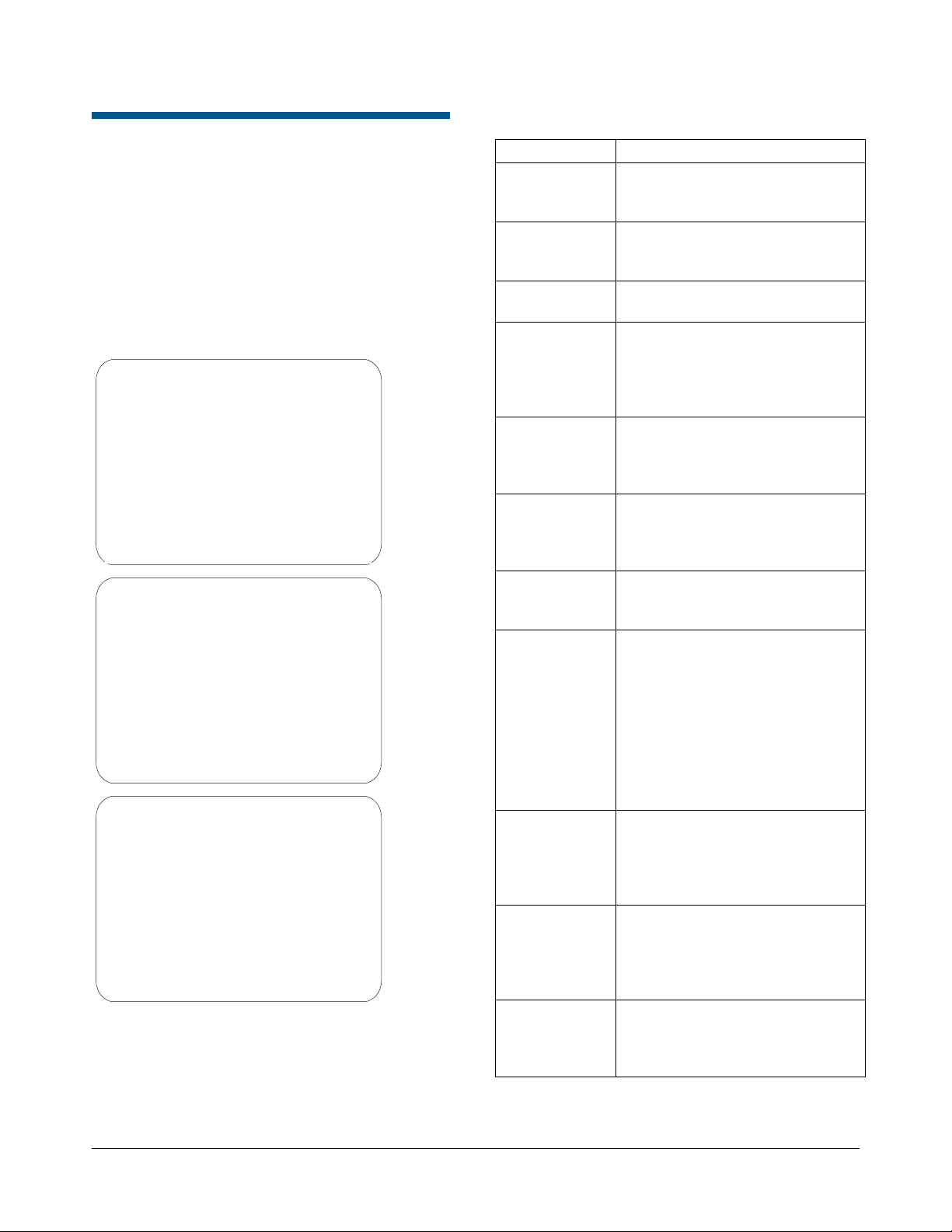
Figure 1: Day/Night Camera Dome DirectSet
Menu (3 screens)
0 TOGGLE DIRECT SET MENU
1 DOME CONFIG MENU
2 AUTO IRIS/AUTO FOCUS
3 FLIP
4 PEEL PATTERN
10 NIGHT MODE
11 DAY MODE
12 AUTO DAY/NIGHT MODE
13 WDR ON
14 WDR OFF
FOCUS NEAR = next page
15 SMOOTH SCAN
16 STEPPED SCAN
17 RANDOM SCAN
20 DOME INFORMATION
51 SEQUENCE 1
52 SEQUENCE 2
53 SEQUENCE 3
54 SEQUENCE 4
55 SEQUENCE 5
56 SEQUENCE 6
FOCUS NEAR = next page
57 SEQUENCE 7
58 SEQUENCE 8
59 SEQUENCE 9
60 SEQUENCE 10
61 SEQUENCE 11
62 SEQUENCE 12
63 SEQUENCE 13
64 SEQUENCE 14
65 SEQUENCE 15
66 SEQUENCE 16
FOCUS NEAR = previous page
To access a feature on the menu, enter the
number and press the DirectSet button (varies by
controller). Table 1 provides a description of the
available options.
Table 1: DirectSet Menu Options
Command Description
0+DirectSet Toggle DirectSet Menu: Toggles
between displaying and hiding
the DirectSet menu.
1+DirectSet Dome Config Menu: Displays the
SpeedDome Ultra configuration
menu.
2+DirectSet Auto Iris/Auto Focus: Resumes
Auto Focus/Auto Iris mode.
3+DirectSet Flip: Rotates the SpeedDome
180° from its current pointing
direction. This is the same as
pressing the Flip button on
compatible controllers.
4+DirectSet Peel Pattern: Runs the default
Apple Peel Pattern. This is the
same as pressing the Peel button
on compatible controllers.
10+DirectSet Night Mode: Sets the dome IR
mode setting to ON. The dome
switches to full-time black-andwhite (B/W) mode.
11+DirectSet Day Mode: Sets the dome IR
mode setting to OFF. The dome
switches to full-time color mode.
12+DirectSet Auto Day/Night Mode: Resumes
the most recently selected
automatic IR mode setting.
• Auto High: B/W mode activates
~30 lux.
• Auto Mid: B/W mode activates
~3 lux.
• Auto Low: B/W mode activates
~ 0.5 lux
13+DirectSet WDR On: Enables Wide Dynamic
Range (WDR). Use this setting
when both bright and low light
areas need to be viewed
simultaneously.
14+DirectSet WDR Off: Disables Wide
Dynamic Range (WDR). Use this
setting when the light level is
constant or when changes in
lighting conditions are gradual.
15+DirectSet Smooth Scan: Initiates a smooth
360° clockwise rotation around
the dome axis using the current
tilt, zoom and focus settings.
SPEEDDOME ULTRA VIIE DAY/NIGHT CAMERA DOME CONFIGURATION UTILITY 8200-0184-12, REV. A
OPERATOR’S MANUAL SUPPLEMENT
2 of 15
Page 3
Command Description
16+DirectSet Stepped Scan: Initiates a
clockwise rotation around the
dome axis pausing briefly every
10° (at 1x zoom) for 3 seconds
using the current tilt, zoom and
focus settings.
17+DirectSet Random Scan: Initiates a
clockwise or counter-clockwise
rotation around the dome axis
using the current tilt, zoom and
focus settings. The dome pauses
randomly as it rotates around the
axis.
20+DirectSet Dome Information: Displays the
Dome Information screen
available through the dome
configuration menu.
51+DirectSet Sequence: Runs Sequence 1
52+DirectSet Sequence: Runs Sequence 2
53+DirectSet Sequence: Runs Sequence 3
54+DirectSet Sequence: Runs Sequence 4
55+DirectSet Sequence: Runs Sequence 5
56+DirectSet Sequence: Runs Sequence 6
57+DirectSet Sequence: Runs Sequence 7
58+DirectSet Sequence: Runs Sequence 8
59+DirectSet Sequence: Runs Sequence 9
60+DirectSet Sequence: Runs Sequence 10
61+DirectSet Sequence: Runs Sequence 11
62+DirectSet Sequence: Runs Sequence 12
63+DirectSet Sequence: Runs Sequence 13
64+DirectSet Sequence: Runs Sequence 14
65+DirectSet Sequence: Runs Sequence 15
66+DirectSet Sequence: Runs Sequence 16
255+DirectSet Admin: Reset Dome (Baxall)
Menu Programming Navigation
The SpeedDome Ultra VIIE is programmed from
on-screen menus that are accessible through your
controller (keyboard, virtual keyboard, or Touch
Tracker
The starting point for programming is the
Configuration Menu. To access the menu on
most controllers press and hold the following
buttons in sequence:
Iris Open > Focus Far > Zoom Out
(Consult your keyboard manual for instructions if
unable to access menu programming.)
When programming dome functions, the primary
buttons used for navigation, item selection, and
value increases or decreases are:
Joystick. The joystick allows you to move the
cursor—represented by highlighting—around the
menus. You can select a field when it is
highlighted.
Focus Far button. Pressing the Focus Far button
selects or enables a choice on a highlighted field.
Zoom In/Out button. Pressing the Zoom In/Out
button scrolls a pre-determined list of values either
up or down in a highlighted field.
®
).
Changing Camera Functions within Presets
When Presets are created, they adopt the dome
parameters defined in the Camera Functions
screen. You can now customize camera functions
for each Preset by accessing the Camera
Functions screen from the Preset screen.
Note: If you change the parameters in the Camera
Functions Menu for an existing Preset, you will
need to reprogram the Preset to save the changes.
Motion Detection Zones associated with the Preset
will also require reprogramming.
Follow the steps below to change camera functions
with Presets:
1. Access the Dome Configuration Menu
(Figure 2) by pressing Iris Open, Focus Far
and Zoom Out on your controller.
SPEEDDOME ULTRA VIIE DAY/NIGHT CAMERA DOME CONFIGURATION UTILITY 8200-0184-12, REV. A
OPERATOR’S MANUAL SUPPLEMENT
3 of 15
Page 4
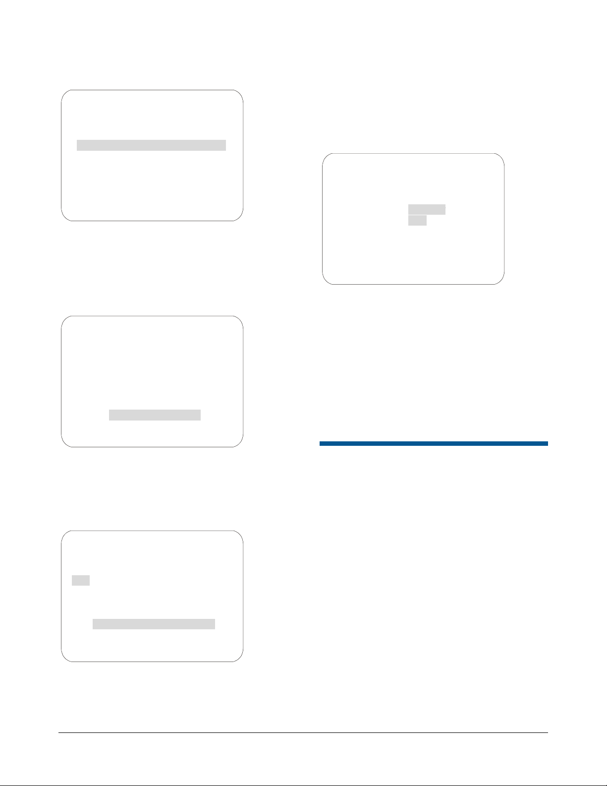
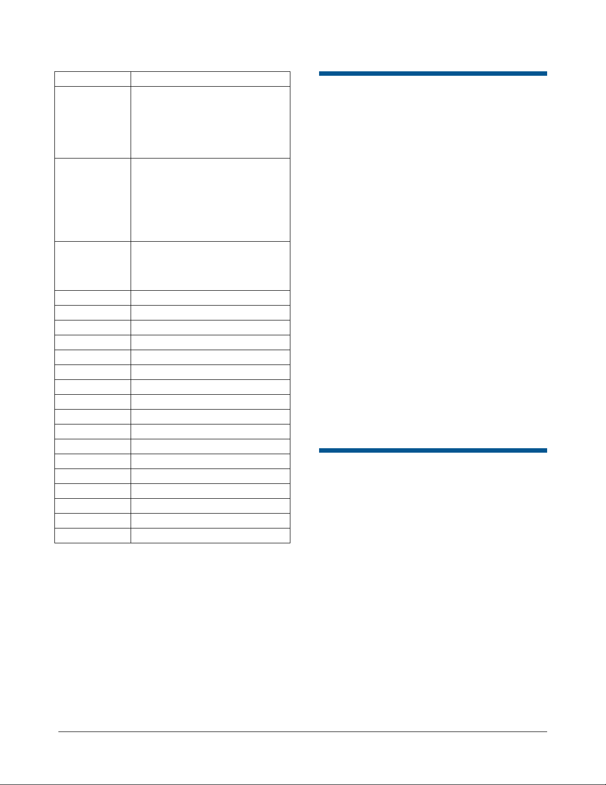
Figure 2.
DOME CONFIGURATION MENU
PAN / TILT / ZOOM / SYNC OPTS
CAMERA FUNCTIONS
ALARMS / AREAS / PRESETS / PZ
ON-SCREEN TEXT DISPLAY
LANGUAGE / PASSWORD
DOME INFORMATION
RESET TO FACTORY SETTINGS
QUIT WITHOUT SAVING
EXIT AND SAVE CHANGES
2. Use the joystick to highlight Alarms / Areas /
Home / Presets / PZ and Press Focus Far to
select. The Alarms / Areas / Home / Presets /
PZ screen appears (Figure 3).
Figure 3.
ALARMS/AREAS/HOME/PRESETS/PZ
SET ALARM ACTIONS
SET ALARM STATES
SET HOME POSITION
SET NORTH POSITION
AREA BOUNDARIES
PRIVACY ZONES
PRESETS
SCAN LIMITS
EXIT
3. Use the joystick to highlight Presets and press
Focus Far to select. The Select Preset To
Program screen appears (Figure 4).
Figure 4.
SELECT PRESET TO PROGRAM
PRESET PRESET NAME
NUMBER
1-96 PRESET 1-96
MOTION DETECTION SETUP
SEQUENCE SETUP MENU
CAMERA FUNCTIONS
FOCUS FAR to program preset
EXIT
4. Use the joystick to highlight the PRESET
NUMBER field and press the Zoom In/Out
button until your desired Preset number
appears.
5. Use the joystick to highlight Camera
Functions and press the Focus Far button.
The Camera Functions screen appears
(Figure 5).
Figure 5.
CAMERA FUNCTIONS
CAMERA FUNCTIONS
Auto White Bal ON
Auto White Bal ON
IR MODE Auto Low
IR MODE Auto Low
WDR OFF
WDR OFF
AGC/Shutter Max Gain Limit
AGC/Shutter Max Gain Limit
Open Shutter 28 dB 1/4 s
Open Shutter 28 dB 1/4 s
RESET TO FACTORY SETTINGS
RESET TO FACTORY SETTINGS
EXIT
EXIT
6. Make your desired changes. For details on the
Camera Functions screen, consult Chapter 3
of the Day/Night Camera Dome Configuration
Utility Operator’s Manual, 8200-0184-04.
7. Use the joystick to highlight EXIT and press the
Focus Far button to select. The Select Preset
to Program screen appears.
8. Program (or reprogram) the Preset by selecting
FOCUS FAR to program preset (see Note on
page 3).
Programming Motion Detection
Applicable Day/Night SpeedDome cameras are
capable of providing motion detection based on
Preset camera views. Motion detection can be
programmed for any of the 96 Presets defined in
the dome. The motion detection feature is
programmed from the Select Preset to Program
screen.
Understanding Motion Zones
Motion Detection is programmed by positioning
motion zones (represented by rectangular blocks)
within a Preset scene. When motion occurs within
any of the motion zones, the dome will respond by
triggering the action you programmed for it—either
an output, a Preset, a Pattern, or by taking no
action.
SPEEDDOME ULTRA VIIE DAY/NIGHT CAMERA DOME CONFIGURATION UTILITY 8200-0184-12, REV. A
OPERATOR’S MANUAL SUPPLEMENT
4 of 15
Page 5
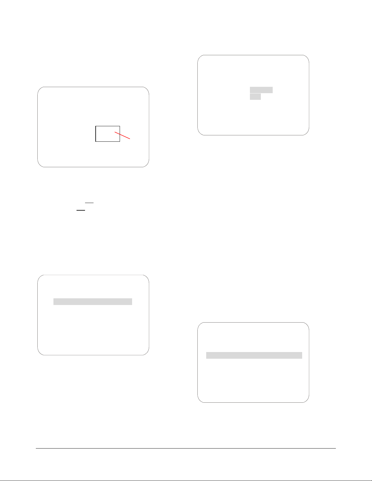
You can create up to eight motion zones for every
Preset scene. An example of a Preset scene with
one motion zone is shown in Figure 6
Figure 6.
MOTION DETECTION SETUP
PRESET 1
ZONE 1
ESC/FOCUS = save & exit
One
motion
zone
IMPORTANT NOTE: Motion Detection will not
function under certain Camera Functions settings.
Before programming, verify the following:
• IR Mode must not
• WDR must not
be set to ON.
be set to ON.
Follow the steps below to change the IR Mode and
WDR settings:
1. Access the Dome Configuration Menu
(Figure 7) by pressing Iris Open, Focus Far
and Zoom Out on your controller.
Figure 8.
CAMERA FUNCTIONS
Auto White Bal ON
IR MODE Auto Low
WDR OFF
AGC/Shutter Max Gain Limit
Open Shutter 28 dB 1/4 s
RESET TO FACTORY SETTINGS
EXIT
3. Use the joystick to highlight the IR MODE field
and press the Zoom In/Out button to change
settings. Options are OFF, ON, Auto Low, Auto
Mid, Auto High.
4. Use the joystick to highlight the WDR field and
press the Zoom In/Out button to change
settings. Options are On, OFF.
5. Use the joystick to highlight EXIT and press
Focus Far to select.
6. When the Dome Configuration Menu
appears, use the joystick to highlight EXIT
AND SAVE CHANGES and press Focus Far.
Steps to Programming Motion Detection
Figure 7.
DOME CONFIGURATION MENU
PAN / TILT / ZOOM / SYNC OPTS
CAMERA FUNCTIONS
ALARMS / AREAS / PRESETS / PZ
ON-SCREEN TEXT DISPLAY
LANGUAGE / PASSWORD
DOME INFORMATION
RESET TO FACTORY SETTINGS
QUIT WITHOUT SAVING
EXIT AND SAVE CHANGES
2. Use the joystick to highlight Camera
Functions and press Focus Far to select. The
Camera Functions screen appears (Figure 8).
Follow the steps below to program motion
detection.
1. Access the Dome Configuration Menu
(Figure 9) by pressing Iris Open, Focus Far
and Zoom Out on your controller.
Figure 9.
DOME CONFIGURATION MENU
PAN / TILT / ZOOM / SYNC OPTS
CAMERA FUNCTIONS
ALARMS / AREAS / PRESETS / PZ
ON-SCREEN TEXT DISPLAY
LANGUAGE / PASSWORD
DOME INFORMATION
RESET TO FACTORY SETTINGS
QUIT WITHOUT SAVING
EXIT AND SAVE CHANGES
2. Use the joystick to highlight Alarms / Areas /
Home / Presets / PZ and Press Focus Far to
select. The Alarms / Areas / Home / Presets /
PZ screen appears (Figure 10).
SPEEDDOME ULTRA VIIE DAY/NIGHT CAMERA DOME CONFIGURATION UTILITY 8200-0184-12, REV. A
OPERATOR’S MANUAL SUPPLEMENT
5 of 15
Page 6

Figure 10.
ALARMS/AREAS/HOME/PRESETS/PZ
SET ALARM ACTIONS
SET ALARM STATES
SET HOME POSITION
SET NORTH POSITION
AREA BOUNDARIES
PRIVACY ZONES
PRESETS
SCAN LIMITS
EXIT
3. Use the joystick to highlight Presets and press
Focus Far to select. The Select Preset To
Program screen appears (Figure 11).
Figure 11.
SELECT PRESET TO PROGRAM
PRESET PRESET NAME
NUMBER
1-96 PRESET 1-96
MOTION DETECTION SETUP
SEQUENCE SETUP MENU
CAMERA FUNCTIONS
FOCUS FAR to program preset
EXIT
4. Use the joystick to highlight Motion Detection
Setup and press Focus Far. The Motion
Detection Setup screen appears (Figure 12).
Figure 12.
MOTION DETECTION SETUP
1 PRESET 1
ZONE SENS ACTION
1 0 NO ACTION XX
HIDE ALL ZONES NO
DELETE ALL ZONES
FOCUS FAR to program zones
EXIT
5. The PRESET number field is highlighted.
Press the Zoom In/Out button until the Preset
number you want to use for this motion
detection setup (1-96) appears.
6. Use the joystick to highlight the ZONE field.
Use the Zoom In/Out button until the zone
number (1-8) you want to apply to the Preset
appears.
7. Use the joystick to highlight the SENS field.
Use the Zoom In/Out button until the
sensitivity level you want to apply to your zone
appears. Note: Zone sensitivity ranges from
zero (no sensitivity) to five (high sensitivity).
Zero is used to disable individual zones on a
temporary basis.
8. Use the joystick to highlight the ACTION field.
Use the Zoom In/Out button until the action
you want appears. Action determines how the
system will respond when motion is detected.
Choices are:
No Action* - no action occurs
Preset (1-96) – calls a Preset
Pattern (1-16) – runs a Pattern
Output (1-4) – activates an output
*When No Action is programmed on the motion
detection screen, the dome’s return to a Home
position is delayed as long as motion occurs within
the time specified on the return-to-home screen.
9. Press the Focus Far button. The Motion
Detection Setup screen appears (Figure 13).
Figure 13.
MOTION DETECTION SETUP
PRESET 1
ZONE 4
ESC/FOCUS = save & exit
10. Using the joystick, move the rectangular zone
indicator to a desired location and press Focus
Far to save and exit. (Note: The rectangular
zone indicator does not appear on-screen until
the joystick is moved.)
11. Repeat steps 6-10 to create additional
detection zones (1-8).
12. When the Motion Detection Setup screen
appears, use the joystick to highlight EXIT and
press Focus In/Out to save.
SPEEDDOME ULTRA VIIE DAY/NIGHT CAMERA DOME CONFIGURATION UTILITY 8200-0184-12, REV. A
OPERATOR’S MANUAL SUPPLEMENT
6 of 15
Page 7

13. Continue to select EXIT on every screen until
menu programming ends.
Note: Motion detection can be hidden without
erasing the motion detection configuration (for
example, during the day when motion is expected).
To hide motion detection, select Yes on the Hide
All Zones field on the Motion Detection Setup
screen.
Activating Motion Detection
Motion detection works in conjunction with existing
Presets. To begin monitoring motion detection, call
the Preset to which motion detection has been
applied.
Note: Motion detection is not guaranteed to
capture 100% of all activity.
Programming Sequences
A Sequence is a sequential display of multiple
camera Presets. Sequences provide a methodical
and effective way to monitor multiple areas of
interest by switching to different Presets
automatically. Sequences are programmed from
the Select Preset to Program screen.
Sequences are created by identifying Preset views
to include in the Sequence and specifying a dwell
time that controls how long each Preset remains on
screen before switching to another Preset. Up to
16 Sequences can be created, each with 16 steps
(Presets).
Steps to Programming Sequences
Figure 14.
DOME CONFIGURATION MENU
PAN / TILT / ZOOM / SYNC OPTS
CAMERA FUNCTIONS
ALARMS / AREAS / PRESETS / PZ
ON-SCREEN TEXT DISPLAY
LANGUAGE / PASSWORD
DOME INFORMATION
RESET TO FACTORY SETTINGS
QUIT WITHOUT SAVING
EXIT AND SAVE CHANGES
2. Use the joystick to highlight Alarms / Areas /
Home / Presets/PZ and Press Focus Far to
select. The Alarms / Areas / Home / Presets /
PZ screen appears (Figure 15).
Figure 15.
ALARMS/AREAS/HOME/PRESETS/PZ
SET ALARM ACTIONS
SET ALARM STATES
SET HOME POSITION
SET NORTH POSITION
AREA BOUNDARIES
PRIVACY ZONES
PRESETS
SCAN LIMITS
EXIT
3. Use the joystick to highlight Presets and press
Focus Far to select. The Select Preset to
Program screen appears (Figure 16).
Figure 16.
Follow the steps below to program Sequences.
1. Access the Dome Configuration Menu
(Figure 14) by pressing Iris Open, Focus Far
and Zoom Out on your controller.
SELECT PRESET TO PROGRAM
PRESET PRESET NAME
NUMBER
1-96 PRESET 1-96
MOTION DETECTION SETUP
SEQUENCE SETUP MENU
CAMERA FUNCTIONS
FOCUS FAR to program preset
EXIT
4. Use the joystick to highlight Sequence Setup
Menu and press Focus Far to select. The
Sequence Setup Menu screen appears
(Figure 17).
SPEEDDOME ULTRA VIIE DAY/NIGHT CAMERA DOME CONFIGURATION UTILITY 8200-0184-12, REV. A
OPERATOR’S MANUAL SUPPLEMENT
7 of 15
Page 8

Figure 17.
STEP 1-4 DWELL TIME
STEP PRESET MIN / SEC
SEQUENCE SETUP MENU
SEQUENCE NUMBER 1
1 1 0 0
2 1 0 0
3 1 0 0
4 1 0 0
EXIT
5. Use the Joystick to highlight the SEQUENCE
NUMBER field. Press Zoom In/Out to change
values (1-16).
6. Use the joystick to highlight the STEP field.
Press Zoom In/Out to scroll through available
steps. Steps are displayed in groups of 1-4, 5-8,
6-12, and 13-16.
7. Use the joystick to highlight the PRESET field
and press Zoom In/Out until the desired Preset
number appears (1-96).
8. Use the joystick to highlight the DWELL TIME
MIN field and press Zoom In/Out until the
number of minutes you want the Preset to
remain on screen appears (0-10 minutes).
9. Use the joystick to highlight the DWELL TIME
SEC field and press Zoom In/Out until the
number of seconds you want the Preset to
remain on screen appears (0-60 seconds in 10second increments).
10. Repeat steps 8 through 10 above until the first 4
presets have been programmed. If more
Presets are desired, highlight to the STEP field
and use Zoom In/Out to display steps 5-8.
11. When finished, use the joystick to highlight
EXIT and press Focus Far to select.
12. At the Dome Configuration Menu screen,
highlight EXIT AND SAVE CHANGES and
press Focus Far to save.
Running Sequences 1-16
Two options are available for running Sequences:
• Option 2 - Use the Set Home Position method
to schedule one Sequence to run when the
dome returns to its home position (after a
defined period of inactivity).
Follow the steps below to run Sequences from the
Set Home Position screen:
1. Access the Dome Configuration Menu
(Figure 18) by pressing Iris Open, Focus Far
and Zoom Out on your controller.
Figure 18.
DOME CONFIGURATION MENU
PAN / TILT / ZOOM / SYNC OPTS
CAMERA FUNCTIONS
ALARMS / AREAS / PRESETS / PZ
ON-SCREEN TEXT DISPLAY
LANGUAGE / PASSWORD
DOME INFORMATION
RESET TO FACTORY SETTINGS
QUIT WITHOUT SAVING
EXIT AND SAVE CHANGES
2. Use the joystick to highlight Alarms / Areas /
Home / Presets / PZ and Press Focus Far to
select. The Alarms / Areas / Home /
Presets/PZ screen appears (Figure 19).
Figure 19.
ALARMS/AREAS/HOME/PRESETS/PZ
SET ALARM ACTIONS
SET ALARM STATES
SET HOME POSITION
SET NORTH POSITION
AREA BOUNDARIES
PRIVACY ZONES
PRESETS
SCAN LIMITS
EXIT
3. Use the joystick to highlight Set Home
Position and press Focus Far to select. The
Set Home Position screen appears
(Figure 20).
• Option 1 – If your keyboard supports the
DirectSet command, you can use it to run a
Sequence immediately (see DirectSet Menu,
page 2). Consult your keyboard manual for
information on DirectSet functions.
SPEEDDOME ULTRA VIIE DAY/NIGHT CAMERA DOME CONFIGURATION UTILITY 8200-0184-12, REV. A
OPERATOR’S MANUAL SUPPLEMENT
8 of 15
Page 9

Figure 20.
SET HOME POSITION
ACTION SEQUENCE 1
RETURN TIME MINS 10
EXIT
4. On the highlighted ACTION field, press the
Zoom In/Out button until Sequence appears.
5. Use the joystick to highlight the number field.
Press the Zoom In/Out button until your
desired Sequence number appears.
6. Use the joystick to highlight the RETURN TIME
MINS field. Press the Zoom In/Out button to
specify when the dome is to return to its home
position after a period of inactivity (1-60 min.).
This will trigger the Sequence to run.
Setting Description
Off
Allows programming of three fixed speed
Patterns. The three Patterns are limited
to a total of 99 pan/tilt/zoom movements
(e.g., if one Pattern uses 50 movements,
the remaining two Patterns are limited to
a total of 49 movements). Note: The
VM1 and VM96 systems only support
the OFF setting.
3
Allows programming of three variable
speed Patterns. Each Pattern can have
up to 99 pan/tilt/zoom movements.
16
Allows programming of 16 variable
speed Patterns. Each Pattern can have
up to 99 pan/tilt/zoom movements.
Use the following steps to configure the dome for
Patterns:
1. Enter the Dome Configuration Menu
(Figure 21) by pressing Iris Open, Focus Far
and Zoom Out on your controller.
Figure 21.
7. Use the joystick to highlight the EXIT field and
press Focus Far to select.
8. Continue to exit until the completely out of all
programming menus.
Note: If a Preset or a Pattern is called by either an
alarm or motion detection while a Sequence is
running, the Sequence will be interrupted.
Pattern Options: Fixed or Variable Speed
A Pattern is a series of programmed pan/tilt/zoom
dome movements. The SpeedDome Ultra VIIE
allows you to create fixed speed or variable speed
Patterns (variable speed Patterns are dependent
on system capability).
The SpeedDome Ultra VIIE provides three options
when configuring the system for Patterns:
DOME CONFIGURATION MENU
PAN / TILT / ZOOM / SYNC OPTS
CAMERA FUNCTIONS
ALARMS / AREAS / PRESETS / PZ
ON-SCREEN TEXT DISPLAY
LANGUAGE / PASSWORD
DOME INFORMATION
RESET TO FACTORY SETTINGS
QUIT WITHOUT SAVING
EXIT AND SAVE CHANGES
2. Use the joystick to highlight On-Screen Text
Display and press Focus Far to select. The
On-Screen Text Display screen appears
(Figure 22).
Figure 22.
ON-SCREEN TEXT DISPLAY
STATUS DISPLAY OFF
DISABLE ALL NAMES? YES
DIAGNOSTIC DISPLAY OFF
DIRECTION INDICATOR OFF
PATTERN SELECT 16
NAME CONFIGURATION MENU
TEXT ATTRIBUTE OPTIONS
EXIT
SPEEDDOME ULTRA VIIE DAY/NIGHT CAMERA DOME CONFIGURATION UTILITY 8200-0184-12, REV. A
OPERATOR’S MANUAL SUPPLEMENT
9 of 15
Page 10

3. Use the joystick to highlight the PATTERN
SELECT field and press Zoom In/Out to select
Off, 3, or 16.
4. Use the joystick to highlight EXIT and press
Focus Far to select. The Dome Configuration
Menu appears.
5. Use the joystick to highlight EXIT AND SAVE
CHANGES and press Focus Far to save.
Recording Patterns When Configured for 16
Recording Patterns when the Pattern Select field
is set for Off, 3, or 16 is accomplished through
keyboard commands (consult your keyboard user
guide). However, additional steps are required
when the Pattern Select field is set for 16.
Follow the steps below to record 16 variable speed
Patterns:
Select screen (Figure 23). Follow the steps below
to run a Pattern.
1. Enter the appropriate keyboard command to
run Patterns 1, 2, or 3. The Pattern Select
screen appears.
2. Move the joystick to highlight the desired
Pattern number (1-16) to run.
3. Press Focus Far to select. The Pattern Select
screen disappears and the Pattern runs.
SensorNet, RS-422,
Manchester, and UTC
Controllers and Switchers
The following provides information about
SensorNet, RS-422, Manchester, and UTC
protocols on SpeedDome Ultra VIIE compatible
controllers.
1. Enter the appropriate keyboard commands to
record a Pattern, using 1, 2, or 3 as your
Pattern number (Consult your keyboard user
guide for specific steps.). The Pattern Select
screen appears (Figure 23)
Figure 23.
PATTERN SELECT
1 5 9 13
1 6 10 14
3 7 11 15
4 8 12 16
EXIT
2. Use the joystick to highlight a desired Pattern
number (1-16). Press Focus Far to continue.
3. Pan/tilt/zoom the dome as desired for the
Pattern.
4. Execute the keyboard’s Pattern save
command to save the Pattern.
Running 16 Patterns
When a dome is configured for 16 Patterns,
running a Pattern requires displaying the Pattern
VM8
Supported Protocol SensorNet
Maximum Presets 0
Maximum Patterns1 1
DirectSet Menu Not supported
Address Range 1-8
Notes:
(1) Apple Peel only. Programmable Patterns are not
available.
VM16/ADTT16 (White Touch Tracker)
Supported Protocol SensorNet
RS-422
Maximum Presets 96 – SensorNet
4 – RS-422
Maximum Patterns2 16
DirectSet Menu Not supported
Address Range 1-16
Notes:
(1) Requires RCSN422 code converter.
(2) Patterns are limited by time and the number of
available dome commands.
1
SPEEDDOME ULTRA VIIE DAY/NIGHT CAMERA DOME CONFIGURATION UTILITY 8200-0184-12, REV. A
OPERATOR’S MANUAL SUPPLEMENT
10 of 15
Page 11

VM16E/ADTT16E (Black Touch Tracker)
Supported Protocol SensorNet
RS-422
Maximum Presets 96 – SensorNet
4 – RS-422
Maximum Patterns2 16
DirectSet Menu Yes3
Address Range 1-16 or 1-643
Notes:
(1) Requires RCSN422 code converter.
(2) Patterns are limited by time and the number of
available dome commands.
(3) Requires firmware version 0701-2833-0103
(EEPROM) / 0701-2834-0201 (Flash PROM) or
newer.
1
VM32/AD32
Supported Protocol SensorNet
RS-422
Maximum Presets 96 – SensorNet
4 – RS-422
Maximum Patterns2 16
DirectSet Menu Not supported
Address Range 1-32
Notes:
(1) Requires RCSN422 code converter.
(2) Patterns are limited by time and the number of
available dome commands.
1
VM961
Supported Protocol SensorNet
RS-422
Maximum Presets 9,9992
Maximum Patterns3 16
DirectSet Menu Not supported
Address Range 1-32
Notes:
(1) Requires software version 5.2 or newer.
(2) Preset information is stored at the host, not the
dome; therefore, divide 9,999 by the number of
domes to determine number of available Presets per
dome.
(3) Patterns are limited by time and the number of
available dome commands.
AD2150/AD2350
Supported Protocol RS-4221
Maximum Presets 162
Maximum Patterns3 16
DirectSet Menu Not supported
Address Range 1-32
Notes:
(1) Requires the AD2083-02 series code converter.
(2) Preset information is stored at the converter, not the
dome.
(3) Patterns are limited by time and the number of
available dome commands.
AD1650
Supported Protocol RS-4221
Maximum Presets 162
Maximum Patterns3 16
DirectSet Menu Not supported
Address Range 1-1284
Notes:
(1) Requires the AD2083-02 series code converter.
(2) Preset information is stored at the converter, not the
dome.
(3) Patterns are limited by time and the number of
available dome commands.
(4) Requires additional equipment to achieve these
numbers. A dome address within each group of 64
or 99 cameras is reserved as a global broadcast
address.
AD168
Supported Protocol SensorNet1 RS-4221
1, 2
Maximum Presets 16
, 64
1, 3
Maximum Patterns4 16
DirectSet Menu Not supported
Address Range SensorNet: 1-180
RS-422: 1-99
1, 5
Notes:
(1) Requires the appropriate code control module.
(2) Requires the AD2083-02 series code converter.
(3) Presets information is stored at the converter or
control module, not the dome.
(4) Patterns are limited by time and the number of
available dome commands.
(5) Requires additional equipment to achieve these
numbers. A dome address within each group of 64
or 99 cameras is reserved as a global broadcast
address.
or 2
or 1-180
2, 5
SPEEDDOME ULTRA VIIE DAY/NIGHT CAMERA DOME CONFIGURATION UTILITY 8200-0184-12, REV. A
OPERATOR’S MANUAL SUPPLEMENT
11 of 15
Page 12

AD2050
MegaPower 1024
Supported Protocol RS-4221
Maximum Presets 162
Maximum Patterns3 16
DirectSet Menu Not supported
Address Range 1-10244
Notes:
(1) Requires the AD2083-02 series code converter.
(2) Preset information is stored at the converter, not the
dome.
(3) Patterns are limited by time and the number of
available dome commands.
(4) Requires additional equipment to achieve these
numbers. A dome address within each group of 64
or 99 cameras is reserved as a global broadcast
address.
MegaPower LT
Supported Protocol SensorNet UTC
Maximum Presets 96 96
Maximum Patterns1 16 16
DirectSet Menu Yes2 Yes2
Address Range 1-99 1-99
Notes:
(1) Patterns are limited by time and the number of
available dome commands.
(2) Requires a compatible keyboard.
Supported Protocol RS-4221 Manchester
Maximum Presets 162 or 603 64
Maximum Patterns4 16 16
DirectSet Menu Not
supported
Not
supported
Address Range 1-10245 1-10245
Notes:
(1) Requires the AD2083-02 series code converter.
(2) Preset information is stored at the converter, not the
dome.
(3) Requires AD2083-02 with firmware version 0701-
11YB-156A or newer. Preset information is stored in
the dome, not the converter.
(4) Patterns are limited by time and the number of
available dome commands.
(5) Requires additional equipment to achieve these
numbers. A dome address within each group of 64
or 99 cameras is reserved as a global broadcast
address.
ADACSNET Control Module1
Supported Protocol USB to RS-232
Maximum Presets 96
Maximum Patterns 16
DirectSet Menu Yes2
Address Range 1-254
Notes:
MegaPower 48
Supported Protocol SensorNet
RS-422
Manchester
(1) Compatible with PCs running Windows® 2000 or
XP and with the Intellex system running version 3.2
or higher software.
(2) Requires USB Dome Control Utility software.
Maximum Presets 961 64
Maximum Patterns2 16 16
DirectSet Menu Yes3 Yes3
Address Range 1-48 1-48
Notes:
(1) Preset information is stored at the host, not the
dome.
(2) Patterns are limited by time and the number of
available dome commands.
(3) Requires firmware 1.07 or newer and a compatible
keyboard.
SPEEDDOME ULTRA VIIE DAY/NIGHT CAMERA DOME CONFIGURATION UTILITY 8200-0184-12, REV. A
OPERATOR’S MANUAL SUPPLEMENT
12 of 15
Page 13

Configuration Menu
Specifications-Indoor Dome
Languages ................English, French, German, Spanish,
Italian, and Portuguese
Operational
Pan/Tilt:
Manual Pan Speed .........................0.2°-100° per second
(scaled to zoom position)
Manual Tilt Speed......................... 0.25°-100° per second
(scaled to zoom position)
Preset Pan/Tilt Speed............ 220° per second maximum
Pan Travel .................................360° continuous rotation
Tilt Travel................................................................ >100°
Pan/Tilt Accuracy..................................................... ±0.5°
23x Day/Night Camera Zoom Functions:
Optical Zoom ............................................................. 23X
Digital Zoom .............................................................. 10X
Zoom Pause .........................................23X selectable or
35X default
Total Zoom .............................................................. 230X
Maximum Zoom Stop....... 46X, 69X, 92X (default), 115X,
138X, 161X, 184X, 207X, 230X
Zoom/Focus Accuracy ........................................... ±0.5%
Auto Synchronization:
Line Locked ........................ Remote V-phase adjustment
Internal.......................................... Built-in sync generator
Address Range....................................................... 1-255
Number of Presets:
VM16 / ADTT16........................... 96 with SensorNet 485
VM32 / AD32 ............................... 96 with SensorNet 485
AD2150..............................................64 with Manchester
16 with RS-422 (using AD2083-02A)
VM96 .................... Virtual with RS-422 or SensorNet 485
VM168 / AD168 ................................64 with Manchester,
RS-422 or SensorNet
16 with RS-422 (using AD2083-02A)
AD2050..............................................64 with Manchester
16 with RS-422 (using AD2083-02A)
Direct View™ Access Time ...........<1 second to position.
Full zoom in <4 seconds.
Focus on VM16, VM32 and
VideoManager systems is <1 second.
Focus on VM96 and RV2715 systems
is <7 seconds
Programmable Patterns
Number Patterns...........................................................16
Storage
Program Storage ................256 Kbytes of Flash memory
Data Storage .................................. 128 Kbytes of SRAM
Electrical
Input Voltage.....................................18-30Vac, 50/60 Hz
UL Class 2 LPS
Design Tolerance ..............................16-36Vac, 50/60 Hz
Power Consumption......................................... 16W max.
Current ........................................................... 0.85A max.
Allowable Drop Out ............................................... 100ms
Power On In-Rush Current........................................1.5A
Surge Protection:
Video Output ............................... Low capacitance Zener
suppressor 6.5V, 1500W
Power Line ......................... TVS rated at 60V, 1.5 joules,
250A 8/20µs impulse
RS-422.......................................... TVS rated at 9.8V/1A,
20V/25A, 500W,
8/20µs impulse
Manchester/
SensorNet 485 .................... Gas discharge tube rated at:
8/20µs impulse discharge current
of 10kA, ten 8/20µs impulse
discharge current of 5kA
Isolation transformer coupled 2000Vrms
PTC fuse protects transformer.
TVS rated at 9.8V/1A, 20V/25A,
500W, 8/20µs impulse
Alarm Input.................................... TVS rated at 9.8V/1A,
20V/25A, 500W, 8/20µs impulse
Alarms Inputs/Control Outputs:
When no I/O board is used:
Inputs ........................................ 1 dry contact/3.5mA sink
Outputs .........................................1 open collector driver
@ 12Vdc, 40mA
When I/O board is used:
Inputs ...................................... 4 dry contacts/3.5mA sink
Outputs ....................................... 4 open collector drivers
@ 12Vdc, 40mA
Environmental
Operating Temperature........ –10° to 50°C (14° to 122°F)
Relative Humidity .....................0 to 95% non-condensing
Storage Temperature ................................ –20°C to 65°C
(–4°F to 149°F)
SPEEDDOME ULTRA VIIE DAY/NIGHT CAMERA DOME CONFIGURATION UTILITY 8200-0184-12, REV. A
OPERATOR’S MANUAL SUPPLEMENT
13 of 15
Page 14

Mechanical
Height ...........................................................20.8cm (8in)
Eyeball Diameter ..........................................12cm (4.7in)
Weight:
Housing and Eyeball ...............................1.36kg (3 lbs)
Base (standard).................................. 0.09kg (0.20 lbs)
Base (with I/O board) .........................0.16kg (0.35 lbs)
Lens Design
Type ................................................................ Aspherical
Focal Length ............................................. 3.6 to 82.8mm
Aperture .................................................f1.6 (wide angle)
f3.7 (telephoto)
Viewing Angle (equivalent to 8-80 mm on 1/2" CCD
array, or 11-110 mm on 2/3" CCD array):
3.6mm ................................................ 54.0°(H) x 40.5°(V)
82.8mm .................................................. 2.5°(H) x 1.9°(V)
Lens and Bubble Densities
Eyeball Lens ..................................................................f0
Bubbles:
RUCLR (Clear)...........................................................f0
RUSLV (Silver)........................................................f2.0
RUSMK (Smoke).....................................................f1.0
RUGLD (Gold).........................................................f2.0
Specifications– 23X Day/Night Camera
Type............................. Interline transfer 1/4in CCD array
Scanning Area ................................. 3.2 (H) x 2.4 (V) mm
Scanning System.......................................... 2:1 interlace
Video Out............................ 1.0 Vp-p/75 ohms composite
Signal-to-Noise ..........................................50 dB (typical)
Horizontal Resolution.......................... 470 lines at center
Minimum Illumination ........ 0.5 lux (AGC On, 20 IRE)
0.03 lux with 1/4 s open shutter
0.01 lux in IR mode
0.009 lux in IR mode with 1/4 s open shutter
White Balance ........................... Through-the-Lens (TTL)
Automatic Tracing
White balance (ATW)
Field-of-View Formulas:
3.2mm* x distance from camera (m)
Focal length (mm)
2.4mm** x distance from camera (m)
Focal length (mm)
* Horizontal scanning area of pickup device (mm) in camera.
** Vertical scanning area of pickup device (mm) in camera.
Example: Wide angle view with lens at 6mm and viewed
object at 10m.
3.2mm x 10m
6mm
2.4mm x 10m
6mm
= 5.33m Horizontal view (m)
= 4.0m Vertical view (m)
= Horizontal view (m)
= Vertical view (m)
NTSC:
Effective Pixels ...........................724 (H) x 494 (V) pixels
Scanning........................... 525 lines, 60 fields, 30 frames
Horizontal ....................................................... 15.734kHz
Vertical.................................................................. 59.9Hz
PAL:
Effective Pixels ...........................724 (H) x 582 (V) pixels
Scanning........................... 625 lines, 50 fields, 25 frames
Horizontal ....................................................... 15.625kHz
Vertical..................................................................... 50Hz
SPEEDDOME ULTRA VIIE DAY/NIGHT CAMERA DOME CONFIGURATION UTILITY 8200-0184-12, REV. A
OPERATOR’S MANUAL SUPPLEMENT
14 of 15
Page 15

Declarations
Regulatory Compliance
Emissions ................................ 47 CFR, Part 15, Class A
ICES-003
EN55022, Class B
EN61000-3-2
EN61000-3-3
AS/NZ 3548, Class A
CISPR 22
Immunity ........................................................ EN50130-4
Safety ..................................................................UL1950
CSA C22.2 No. 950
EN60950
IEC 60950
FCC COMPLIANCE: This equipment complies with Part 15
of the FCC rules for intentional radiators and Class A digital
devices when installed and used in accordance with the
instruction manual. Following these rules provides reasonable
protection against harmful interference from equipment
operated in a commercial area. This equipment should not be
installed in a residential area as it can radiate radio frequency
energy that could interfere with radio communications, a
situation the user would have to fix at their own expense.
EQUIPMENT MODIFICATION CAUTION: Equipment
changes or modifications not expressly approved by
Sensormatic Electronics Corporation, the party responsible for
FCC compliance, could void the user's authority to operate the
equipment and could create a hazardous condition.
Other Declarations
Thank you for using American Dynamics products. We
support our products through an extensive and worldwide
network of dealers. The dealer, through whom you originally
purchased this product, is your point of contact if you have a
need for service or support. Our dealers are fully empowered
to provide the very best in customer service and support.
Dealers should contact American Dynamics at (800) 507-6268
or (561) 912-6259 or on the web at
www.americandynamics.net.
WARRANTY DISCLAIMER: Sensormatic Electronics
Corporation makes no representation or warranty with respect
to the contents hereof and specifically disclaims any implied
warranties of merchantability or fitness for any particular
purpose.
NOTICE: The information in this manual was current when
published. The manufacturer reserves the right to revise and
improve its products. All specifications are therefore subject to
change without notice.
LIMITED RIGHTS NOTICE: For units of the Department
of Defense, all documentation and manuals were developed at
private expense and no part of it was developed using
Government Funds. The restrictions governing the use and
disclosure of technical data marked with this legend are set
forth in the definition of “limited rights” in paragraph (a) (15)
of the clause of DFARS 252.227.7013. Unpublished - rights
reserved under the Copyright Laws of the United States.
TRADEMARK NOTICE: American Dynamics, Sensormatic,
and SpeedDome are trademarks or registered trademarks of
Sensormatic Electronics Corporation. Other product names
mentioned herein may be trademarks or registered trademarks
of Sensormatic or other companies.
COPYRIGHT: Under copyright laws, the contents of this
manual may not be copied, photocopied, reproduced,
translated or reduced to any electronic medium or machinereadable form, in whole or in part, without prior written
consent of Sensormatic Electronics Corporation.
RLJ 12/2004
www.americandynamics.net
SPEEDDOME ULTRA VIIE DAY/NIGHT CAMERA DOME CONFIGURATION UTILITY 8200-0184-12, REV. A
OPERATOR’S MANUAL SUPPLEMENT
15 of 15
 Loading...