

Page 1

Installation Guide
IP SpeedDome Ultra 8
Version 1.0
Part Number 8200-0885-01 A0
Page 2

Notice
The information in this manual was current when published. The manufacturer reserves the right to revise and improve its
products. All specifications are therefore subject to change without notice.
Copyright
Under copyright laws, the contents of this manual may not be copied, photocopied, reproduced, translated or reduced to
any electronic medium or machine-readable form, in whole or in part, without prior written consent of Tyco International Ltd.
© 2008 and its Respective Companies. All Rights Reserved.
American Dynamics
6600 Congress Avenue
Boca Raton, FL 33487 U.S.A.
Customer Service
Thank you for using American Dynamics products. We support our products through an extensive worldwide network of
dealers. The dealer through whom you originally purchased this product is your point of contact if you need service or
support. Our dealers are empowered to provide the very best in customer service and support. Dealers should contact
American Dynamics at (800) 507-6268 or (561) 912-6259 or on the Web at www.americandynamics.net.
Trademarks
Intellex® is a registered trademark of Sensormatic Electronics Corporation. Windows® is a registered trademark of
Microsoft Corporation. PS/2® is a registered trademark of International Business Machines Corporation. Sony® is a
registered trademark of Sony Corporation.
Trademarked names are used throughout this manual. Rather than place a symbol at each occurrence, trademarked
names are designated with initial capitalization. Inclusion or exclusion is not a judgment on the validity or legal status of the
term.
ii Installation Guide
Page 3
Warnings
To reduce risk of electric shock, do not remove cover. No user serviceable parts inside. Refer servicing to
qualified service personnel.
Do not expose this appliance to rain or moisture.
Do not install this product in hazardous areas where highly combustible or explosive products are stored or
used.
The lightning flash/arrowhead symbol, within an equilateral triangle, alerts the user to the presence of a shock
hazard within the product’s enclosure.
Underwriters Laboratories Inc. (“UL”) has not tested the performance or reliability of the security or signaling aspects
of this product. UL has only tested for fire, shock or casualty hazards as outlined in the UL's Standard for Safety UL
60950-1. UL Certification does not cover the perf ormance or reliability of the security or signaling aspects of
this product. UL makes no representations, warranties or certifications whatsoever regarding the
performance or reliability of any security or signaling related functions of this product.
Note to Camera System Installer - This reminder is provided to call the camera system installer's attention to
Section 820.93 of the National Electrical Code, ANSI/NFPA 70: 2005, which provides guidelines for proper grounding
and, in particular, specifies that the coaxial cable shield shall be connected to the grounding system of the building,
as close to the point of cable entry as practical.
This equipment has been tested and found to comply with the limits for a Class “A” digital device, pursuant to part 15
of the FCC Rules. These limits are designed to provide reasonable protection against harmful interference when the
equipment is operated in a commercial environment. This equipment generates, uses and can radiate radio
frequency energy and, if not installed and used in accordance with the instruction manual, may cause interference to
radio communications. Operation of this equipment in a residential area is likely to cause harmful interference in
which case the user will be required to correct the interference at their own expense.
Changes or modifications not expressly approved by Tyco International, the party responsible for FCC compliance,
could void the user’s authority to operate the equipment.
This product was FCC verified under test conditions that included the use of shielded I/O cables and connectors
between system components. To be in compliance with FCC regulations, the user must use shielded cables and
connectors for all except power and alarm cables.
This class A digital apparatus complies with Canadian ICES-003.
Cet appareil numérique de la classe A est conforme à la norme NMB-003 du Canada.
iii
Page 4

iv Installation Guide
Page 5

Table of Contents
About this guide
The SpeedDome Ultra 8 can be installed using the following mounts. . . . . . . 1-1
General Requirements. . . . . . . . . . . . . . . . . . . . . . . . . . . . . . . . . . . . . . . . . . . 1-2
Save Packaging Material. . . . . . . . . . . . . . . . . . . . . . . . . . . . . . . . . . . . . . . . . 1-2
Introduction
Installation . . . . . . . . . . . . . . . . . . . . . . . . . . . . . . . . . . . . . . . . . . . . . . . . . . . . . . . . 2-1
Installation process . . . . . . . . . . . . . . . . . . . . . . . . . . . . . . . . . . . . . . . . . . . . . . . 2-2
Installing IP SDU8 with an Indoor Hardmount
Preparing and installing the Indoor Hardmount Housing . . . . . . . . . . . . . . . . . 3-1
Parts Required . . . . . . . . . . . . . . . . . . . . . . . . . . . . . . . . . . . . . . . . . . . . . . . 3-1
Tools Required . . . . . . . . . . . . . . . . . . . . . . . . . . . . . . . . . . . . . . . . . . . . . . . 3-1
Mounting Requirements . . . . . . . . . . . . . . . . . . . . . . . . . . . . . . . . . . . . . . . . 3-1
Installing IP SpeedDome Ultra 8 with a RHOPN Pendant Mounting
Assembly of the RHOPN Pendant Mount . . . . . . . . . . . . . . . . . . . . . . . . . . . . 4-1
Parts Supplied . . . . . . . . . . . . . . . . . . . . . . . . . . . . . . . . . . . . . . . . . . . . . . . 4-1
Parts to Be Purchased . . . . . . . . . . . . . . . . . . . . . . . . . . . . . . . . . . . . . . . . . 4-1
Tools Required . . . . . . . . . . . . . . . . . . . . . . . . . . . . . . . . . . . . . . . . . . . . . . . 4-1
Preparing the Pendant Housing. . . . . . . . . . . . . . . . . . . . . . . . . . . . . . . . . . . . 4-5
Parts required . . . . . . . . . . . . . . . . . . . . . . . . . . . . . . . . . . . . . . . . . . . . . . . . 4-5
Tools Required . . . . . . . . . . . . . . . . . . . . . . . . . . . . . . . . . . . . . . . . . . . . . . . 4-5
Attaching the Bubble to the IP SpeedDome Ultra 8 Unit . . . . . . . . . . . . . . . . . 4-8
Installing IP SDU8 with a ROENDC End Cap
Preparing and installing the SDU8 Camera in an End Cap Assembly. . . . . . . 5-1
Parts Supplied . . . . . . . . . . . . . . . . . . . . . . . . . . . . . . . . . . . . . . . . . . . . . . . 5-1
Parts Required . . . . . . . . . . . . . . . . . . . . . . . . . . . . . . . . . . . . . . . . . . . . . . . 5-1
Tools Required . . . . . . . . . . . . . . . . . . . . . . . . . . . . . . . . . . . . . . . . . . . . . . . 5-1
Preparing and installing the SDU8 Camera in an End Cap Assembly. . . . . . . 5-2
Attaching the Bubble to the IP SDU8 Unit. . . . . . . . . . . . . . . . . . . . . . . . . . . . 5-7
Restoring factory defaults
Resetting the IPSDU8 . . . . . . . . . . . . . . . . . . . . . . . . . . . . . . . . . . . . . . . . . . . 6-1
Restoring factory defaults on the IPSDU8 . . . . . . . . . . . . . . . . . . . . . . . . . . . . 6-2
v
Page 6

Table of Contents
Technical Specifications
Diagnostic LEDs . . . . . . . . . . . . . . . . . . . . . . . . . . . . . . . . . . . . . . . . . . . . . . . . . 7-1
Diagnostic LED Status Descriptions . . . . . . . . . . . . . . . . . . . . . . . . . . . . . . . . 7-1
Power LED (green). . . . . . . . . . . . . . . . . . . . . . . . . . . . . . . . . . . . . . . . . . . . 7-1
Video/Alarm LED (yellow). . . . . . . . . . . . . . . . . . . . . . . . . . . . . . . . . . . . . . . 7-1
Client LED (orange) . . . . . . . . . . . . . . . . . . . . . . . . . . . . . . . . . . . . . . . . . . . 7-1
Pin Outs for the IP SpeedDome Ultra 8 . . . . . . . . . . . . . . . . . . . . . . . . . . . . . . . 7-2
3 wire 24VAC supply . . . . . . . . . . . . . . . . . . . . . . . . . . . . . . . . . . . . . . . . . . . . 7-2
RJ-45 Ethernet interface (with female to fem ale adaptor) . . . . . . . . . . . . . . . . 7-2
Alarm connector pin-out for Indoor I/O base . . . . . . . . . . . . . . . . . . . . . . . . . . 7-3
Alarm Out Connector is Black and Alarm in is White . . . . . . . . . . . . . . . . . . 7-3
Alarm connector pin-out for Outdoor I/O base. . . . . . . . . . . . . . . . . . . . . . . . . 7-3
Alarm Out Connector is Black and Alarm in is White . . . . . . . . . . . . . . . . . . 7-3
List of Procedures
Procedure 3-1 Preparing and installing the Indoor Hardmount Housing. . . . . . . 3-2
Procedure 3-2 Attaching the Bubble to the IP SDU8 Unit . . . . . . . . . . . . . . . . . 3-6
Procedure 4-1 Assembly of IP SpeedDome Ultra
Camera 8 RHOPN Pendant Mount . . . . . . . . . . . . . . . . . . . . . . . . . . . . . . . . . . . 4-2
Procedure 4-2 Preparing the Pendant Housing and
attaching the SpeedDome Ultra 8 Camera . . . . . . . . . . . . . . . . . . . . . . . . . . . . . 4-5
Procedure 4-3 Attaching the Bubble to the IP SpeedDome Ultra 8 Unit . . . . . . 4-8
Procedure 5-1 Preparing and installing the SDU8 Camera
in an End Cap Assembly. . . . . . . . . . . . . . . . . . . . . . . . . . . . . . . . . . . . . . . . . . . 5-2
Procedure 5-2 Attaching the Bubble to the IP SDU8 Unit . . . . . . . . . . . . . . . . . 5-7
Procedure 6-1 Restoring the IPSDU8 factory defaults . . . . . . . . . . . . . . . . . . . . 6-2
vi Installation Guide
Page 7
1 About this guide
This guide explains how to:
• Prepare and assemble the IP SpeedDome Ultra 8 for installation.
• Install the IP SpeedDome Ultra 8 into the supported housing structures.
• Install the supported housing structures.
This guide supersedes any existing SpeedDome Ultra 8 Install documentation.
This guide assumes that correct data and power points are available to allow connection of the IP
SpeedDome Ultra.
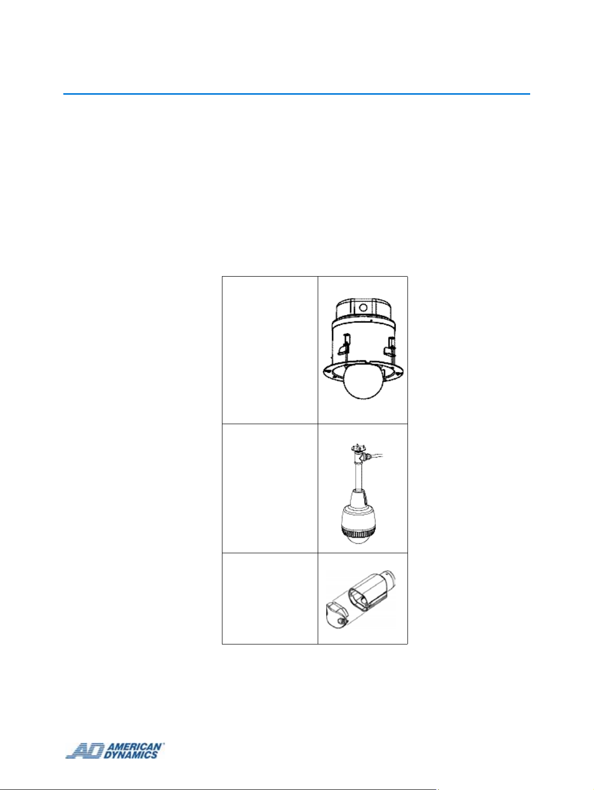
The SpeedDome Ultra 8 can be installed using the following mounts
Indoor Hard Mount
RHOPN
Indoor/Outdoor
Pendant Mount
ROENDC
End Cap
Indoor/Outdoor
To ensure a smooth and successful installation, observe the following requirements.
1-1
Page 8
General Requirements
Have electrical work comply with all applicable local codes and ordinances.
Verify existing site conditions and coordinate with the owner's representative and appropriate
utilities as required.
Obtain copies of all related plans, specifications, shop drawings and addenda to schedule and
coordinate related work.
Thoroughly review the project to ensure that all work meets or exceeds th e above requirements.
Bring alleged discrepancies to the attention of the CCTV Project Coordinator.
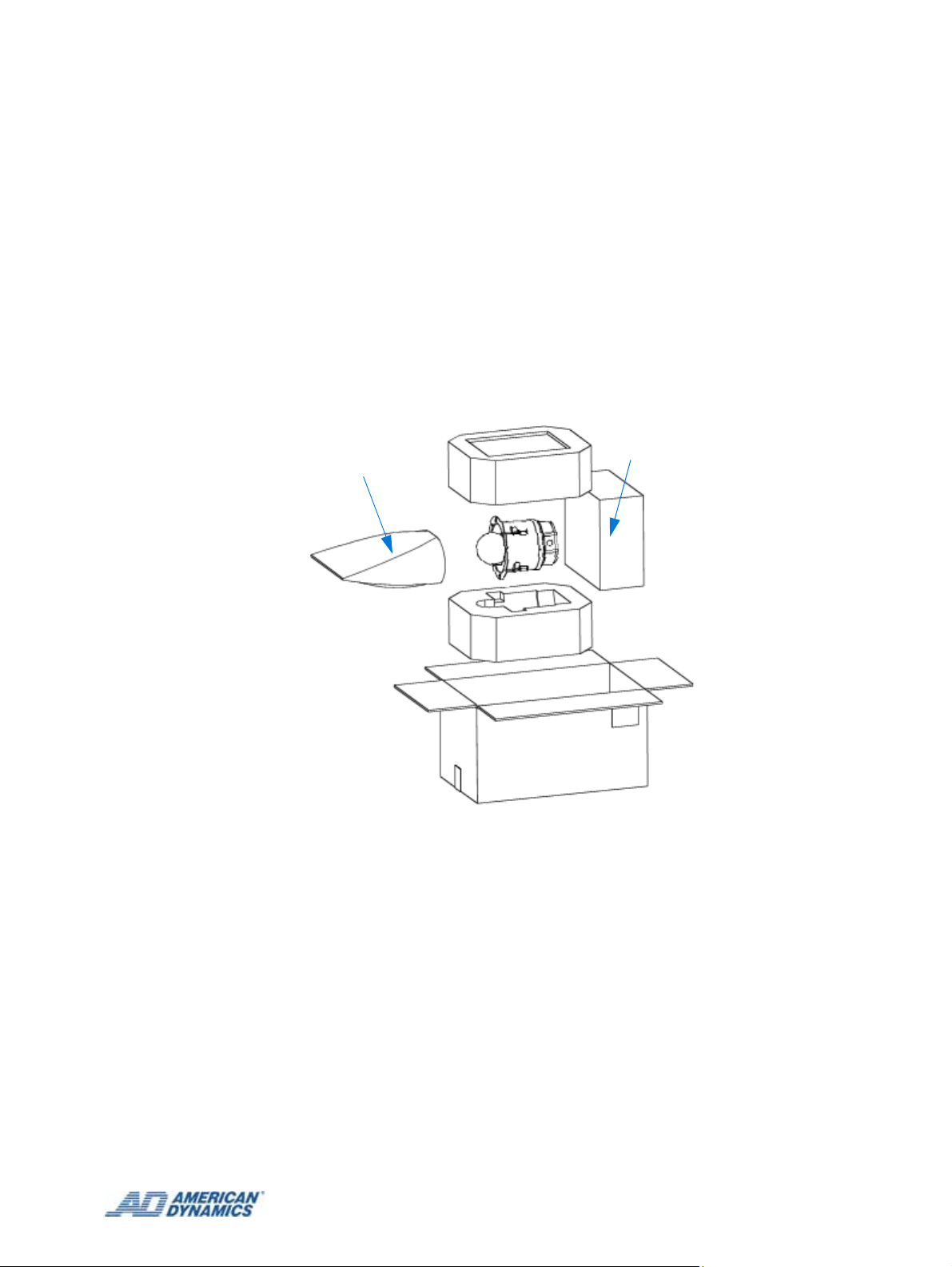
Save Packaging Material
Should the camera dome need to be sent to a repair center , use the p acka ging that the dome was
shipped in.
Box for
Plastic Bag
Bubble
Figure 1-1 Example of Packaging material
1-2
Page 9

Installation
The IPSDU8 can be installed in the following ways: Indoor Hardmount, using a RHOPN pendant
mount, and using a ROENDC End Cap assembly.
Up to 16 IPSDU8s, supplying a maximum of 16 video inputs, can be connected to one Intellex IP
unit, or up to 128 IPSDU8 units can be connected to one VideoEdge™ NVR unit, depending on
the licensing.
Note
More than four domes moving at one time may result in lost frames.
The basic steps involved in installing this product are outlined below:
• Install the hardware
• Configure the software and camera settings.
Note
As all the IPSDU8s have the same IP address, to avoid IP conflicts, each camera must either have
its TCP/IP settings pre-configured, or be installed to the network one at a time.
2 Introduction
The full installation process is detailed in the flowchart on the next page.
2-1
Page 10
Introduction
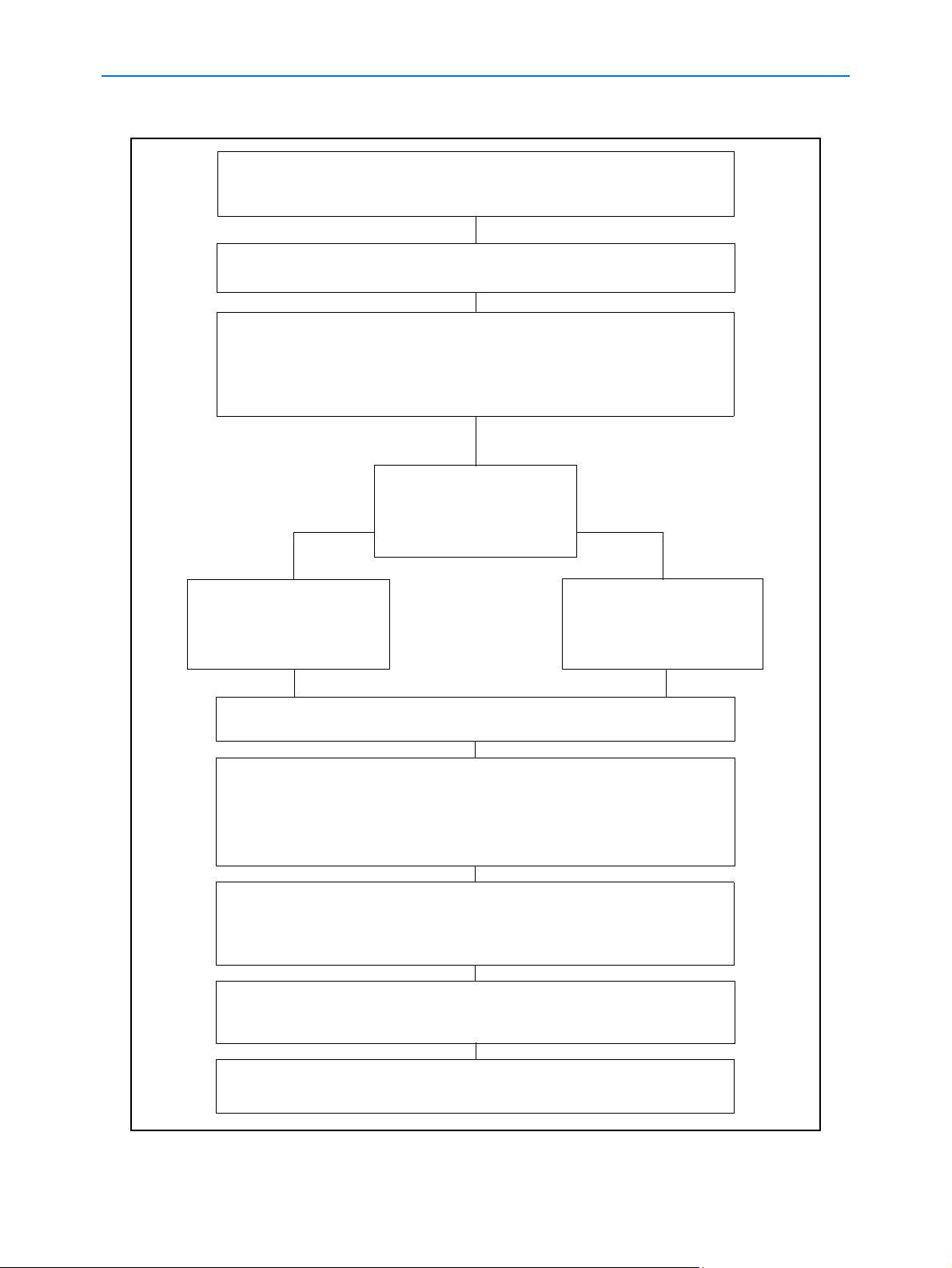
Installation process
Ensure the required power, network and alarm cables are
installed and the network cable is labelled and disconnected at
the network patch panel or access point.
Remove the IPSDU8, dome camera and corr es po nd in g mo u nt fr om
their packaging.
Referring to the IPSDU8 Installation Guide (8200-0885-01) install
the following:
• Mount (which has PCB and cables installed)
• SDU8
• Bubble
Is the IPSDU8 on the
NO YES
same subnet address
as the Intellex or
VideoEdge™ NVR?
Connect a laptop to the
IPSDU8 Ethernet cable
located at the patch
panel or access point.
Open a browser window and enter the IP address of the IPSDU8,
192.168.1.80.
Refer to Web Configuration (Chapter 3) and configure the following
settings on the IPSDU8:
• TCP/IP settings
• Video Input (if applicable)
• Event Inputs (if applicable)
Within the browser window navigate to the Live video page and follow
the Web Configuration chapter to access the SDU8 dome configuration
menu, then using the SDU8 User Manuals, configure the required
dome settings.
If a laptop was used to configure the IPSDU8, disconnect the laptop
and connect the IPSDU8 Ethernet cable into the network patch panel
or access point.
Connect the IPSDU8
Ethernet cable into
the network patch
panel or access point.
Refer to the Intellex/VideoEdge™ NVR Setup Guide and follow the
procedure for adding a IPSDU8.
Figure 2-2 Installation process flowchart
2-2 Installation Guide
Page 11

3 Installing IP SDU8 with an Indoor Hardmount
Preparing and installing the Indoor Hardmount Housing
Parts Required
• RJ-45 connector
• RJ-45 inline coupler adapter
• 3 way power connector, 2109-0651-03
• 6 way alarm connector , 2109-0648-06
• 5 way alarm connector , 2109-0650-05
Note
For installation to a tile ceiling, also order the UL-approved RH2x2 Metal Plate Mounting Kit.
• Install Kit, 0352-0020-01
• Wire, hanging 3.6m (12ft), 2898-0007-01
• Card, quick connect, 12402-2055-02
• Template, cutout, hard mount, 12402-2054-01
Tools Required
• Screwdriver
• Pliers
• RJ-45 crimping tool
• Power drill
•Hammer
• Socket wrench kit with extension (metric)
Mounting Requirements
• Mounting space: ensure there is the following space above the ceiling to accommodate the
dome.
• Height above ceiling:
• Using side entry conduit – 230mm (9.1in)
• Using top entry conduit – 330mm (13 in), assuming a 75mm (3 in) right angled fitting is
employed to minimize the height
• Diameter: 192mm (7.5in)
• Structural members: verify that ceiling members can support the camera dome and mounting
structure, if used.
3-1
Page 12
Procedure 3-1 describes how to prepare the hardmount housing before attaching the SDU8.
Procedure 3-1 Preparing and installing the Indoor Hardmount Housing
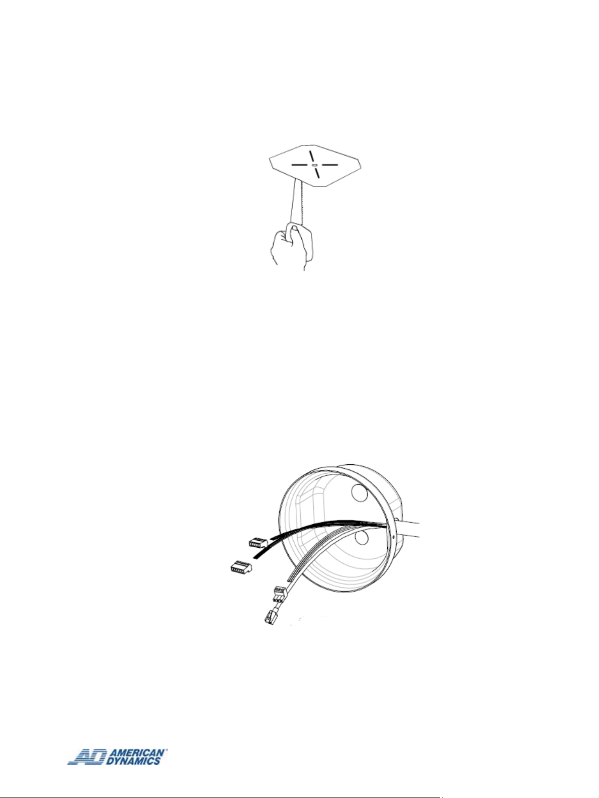
1 Using template supplied, cut a hole in the ceiling.
Figure 3-1 Cutting hole using template
If a junction box or patch panel is being used then:
2 Prepare cabling of sufficien t length to en sure connectio n of the IP SpeedDome® to the junction
box/patch panel and to enable easy servicing.
If a junction box or patch panel is not being used then, ensure that the appropriate cables are in
place for the installation.
3 Remove the hardmount housing from packaging.
4 Remove the two lock screws and remove the hardmount cover to expose the connectors and
settings at the top of the Hardmount.
5 Remove 2.5-3.8cm (1-1.5in) of jacket from the cable end(s) and install power and data
connectors supplied. See
Pin Outs for the IP SpeedDome Ultra 8 on page 7-2 for more details.
Figure 3-2 Cabling the Hardmount cover
6 Pass the cable through the knockout hole in the hardmount cover as shown in Figure 3-2.
7 Plug the power and data connectors from the incoming cable to the corresponding to
connectors on the pigtail leads on the board.
8 Reattach the cover plate.
3-2
Page 13
Installing IP SDU8 with an Indoor Hardmount
At this stage you should prepare the SDU8 Camera for connection to the housing.
Note
The SDU8 Camera’s default physical address is set to 001 and should not need to be changed. If
this address is changed then you should ensure that a record of the new address is kept. During
the software installation ensure the dome configuration address is updated to match the domes
physical address via the Live Video page on the Web GUI in order for camera control to be
maintained. To change the SDU8 physical address, refer to SpeedDome
®
Ultra 8 Camera Dome
Operator’s Guide 8200-0600-01.
9 Gently swivel eyeball to totally expose one of two slot covers.
Figure 3-3 Removing the slot covers
Caution
Swiveling the eyeball fast can damage gears.
10 Insert small, thin-bladed screwdriver into space between cover and eyeball.
11 Gently pry off slot cover.
12 Gently swivel eyeball to totally expose remaining slot cover. With other cover removed, this
cover can be easily removed.
13 Connect the housing and eyeball assembly to the base by aligning the Cap and Base tabs.
3-3
Page 14

Installing IP SDU8 with an Indoor Hardmount
Base Tab
Cap Tab
Figure 3-4 Aligning the Cap and Base tabs
14 Turn the eyeball assembly clockwise until you hear a click.
Figure 3-5 Locking the eyeball assembly
15 For ease of installation, adjust the two "swing out" mounting clips for ceiling thickness.
Figure 3-6 Adjusting the mounting clips
Using safety wire, attach the dome to a strong structural ceiling member as follows:
3-4 Installation Guide
Page 15

Installing IP SDU8 with an Indoor Hardmount
16 Find a strong structural member capable of supporting the dome.
Warning
Do not secure to any component of a fire control system.
17 Wrap one end of the wire around this member and twist the wire around itself four times to
secure.
18 Run the other end of the wire through one of the holes above the swing out tabs.
19 Twist the wire around itself four times to secure.
Warning
To minimize the risk of damage to the unit in case of mounting failure, keep the wire as taut as possible.
Figure 3-7 Securing the housing with safety wire
20 Insert the dome into the hole in the ceiling.
3-5
Page 16

Installing IP SDU8 with an Indoor Hardmount
Figure 3-8 Inserting the IP SDU8 into ceiling
21 Turn each of the two locking screws clockwise to fully extend the "swing out" mounting clips
and to seat them tightly against the top surface of the ceiling.
Figure 3-9 Securing the IP SDU8 with the Mounting clips
22 Apply power to dome.
When power is applied, the dome checks its functionality by performing a homing routine
during which the camera pans and then either goes to the start point of the "apple peel" pattern,
or if powered up once before, to the last position in memory. Once the camera stops, the
camera is online and is ready to be controlled.
Green, Orange, and Yellow LEDs will light in various patterns to indicate status. Typically, you
do not need to view these LEDs unless a failure occurs during or after the routine. See
Diagnostic LED Status Descriptions on page 7-1 for an explanation of the LED patterns.
Once the homing routine completes, affix the bubble to the dome as described in
Procedure 3-2.
Attaching the Bubble to the IP SDU8 Unit (EQ 1)
Procedure 3-2 describes how to attach the bubble assemb ly to th e ins talled IP SDU8 unit.
Procedure 3-2 Attaching the Bubble to the IP SDU8 Unit
1 Remove the bubble assembly from the package and ensure the bubble is clea n and free of
debris.
3-6 Installation Guide
Page 17

Installing IP SDU8 with an Indoor Hardmount
Figure 3-10 Attaching the Lanyard
2 Place the large hole at the end of the lanyard over the scr ew head of the bubble and pull its end
to snap it in place. Loop the lanyard to the inside of the housing.
Figure 3-11 Attaching the bubble assembly
3 Center the bubble over the dome housing and align it s tabs with the mating t abs in the housin g.
Figure 3-12 Locking the bubble
4 Turn the bubble clockwise until it catches the tabs and locks.
Caution
If the network subnet is different from the default camera subnet of 192.168.1.80 then a laptop must be
directly connected to the camera in order to configure the network settings correctly.
5 Refer to the Web Configuration Guide (8200-0885-02) for instructions on configuring the IP
SDU8 configuration settings.
3-7
Page 18

Installing IP SDU8 with an Indoor Hardmount
3-8 Installation Guide
Page 19

4 Installing IP SpeedDome Ultra 8 with a RHOPN
Pendant Mounting
Assembly of the RHOPN Pendant Mount
Parts Supplied
• Support,10500-9641-01
• Cover, 10500-9588-01
• O-Ring, 12500-0022-07
• Screw, 20500-3494-01
• Retainer, 22852-0001-02
• Gasket, 10500-9801-01
• Install Kit, 0351-2119-01
• Anchor, M6, Wedge with hardware, 42880-0108-01
• Washer, Locking, M6 45846-0500-020
• Tee, 3.18cm, (1¼ in), 11417-0040-01
• Nipple, 3.18cm, (1¼ in), 11417-0041-01
• Flange, 3.18cm, (1¼ in), 11400-0069-01
• Screw, M3X12, 25801-1071-120
• Wrench, Tamperproof, Torx, 11400-0149-01
• Bushing, 11400-0047-01
• Connector, Liquid-Tight, 16010-0117-01
• Tape, Teflon, 1 roll, 3200-0229-01
• 6mm Drill Bit, 11400-0197-01
Parts to Be Purchased
• 3.2cm (1¼ in) galvanized steel pipe, NPT threaded at both ends. This part meets UL safety
standard UL 1950 up to a maximum length of 3m (10ft).
• 1.9cm (¾ in) conduit.
Tools Required
• Power drill
•Hammer
• Pliers
• Socket wrench kit with extension (metric)
4-1
Page 20

Procedure 4-1 Describes how to assemble the IP SpeedDome Ultra Camera RHOPN pendant
mount.
Procedure 4-1 Assembly of IP SpeedDome Ultra Camera 8 RHOPN Pendant Mount
If mounting to a steel I-Beam, purchase I-Beam Mount RHIUIB.
1 To install the I-Beam Mount RHIUIB refer to instructions in the packaging then proceed to
step 6.
If mounting to a concrete ceiling, use the flange as a template.
2 Mark hole locations on ceiling.
3 Drill holes with the 6mm drill bit provided.
4 Install anchor hardware.
A
B
C
Figure 4-1 Assembly of flange and ceiling mounting
5 Attach anchor to ceiling using washers (A), lock washers (B), and nuts (C).
6 Cut four 30cm (12in) lengths of Teflon tape.
A
C
D
B
Figure 4-2 Assembly of the pipe tee section
7 Holding nipple (A), tightly wrap a length of tape clockwise over its threads.
4-2
Page 21

Installing IP SpeedDome Ultra 8 with a RHOPN Pendant Mounting
8 Repeat for its other end (A).
9 Tightly wrap a length of tape cloc kwise over the outside threads of bushing (C).
10 Tightly wrap a length of tape clockwise over the liquid-tight connector (D).
11 Thread nipple (A) into the flange.
12 Thread pipe tee (B) into the nipple.
13 Connect bushing (C) into the pipe tee (B).
14 Connect the liquid-tight connector (D) into the bushing (C).
15 Cut two 30cm (12in) lengths of Teflon tape.
G
F
H
Figure 4-3 Assembly of Pendant mounting
16 Holding straight pipe (F) so that you are looking into its threaded end, tightly wrap a length of
tape clockwise over threads so it conforms to the threads.
17 Tightly wrap a length of tape clockwise over threads so it conforms to the threads of the str aight
pipe's (F) other end. Insert straight pipe (F) into pipe tee (G).
A
F
B
Figure 4-4 Attaching the housing
18 Slip cover (A) over the straight pipe (F), then thread the support (B) onto the pipe (F).
4-3
Page 22

Installing IP SpeedDome Ultra 8 with a RHOPN Pendant Mounting
It is suggested you position the cover (A) as shown in Figure 4-5 to aid in the connection of the
prepared pendant housing as described in Procedure 4-2.
A
Figure 4-5 Recommended cover position during pendant connection
If a junction box or patch panel is being used:
19 Prepare cabling of sufficient length to ensure connection of the IP SpeedDome to the junction
box/patch panel and to enable easy servicing an d then route cable (H) th rough the pip e tee (G)
and the pipe (F) as shown in
Figure 4-3.
If a junction box or patch panel is not being used:
20 Ensure that the appropriate cables are in place for the installation and then route cable (H)
through the pipe tee (G) and the pipe (F) as shown in
Figure 4-3.
Caution
To reduce the risk of cable damage caused by excessive ‘pull back’ it is recommended that you only pass
enough cable through the support to facilitate connection.
21 Pass the cable through the top of the support and fold the incoming cables back on
themselves.
22 Remove 2.5-3.8cm (1-1.5in) of jacket from the cable end(s) and install power and data
connectors supplied. See Pin Outs for the IP SpeedDome Ultra 8 on page 7-2 for more details.
4-4 Installation Guide
Page 23

Installing IP SpeedDome Ultra 8 with a RHOPN Pendant Mounting
Preparing the Pendant Housing
Parts required
• RJ-45 connector
• RJ-45 inline coupler adapter
• 3 way power connector, 2109-0651-03
• 6 way alarm connector , 2109-0648-06
• 5 way alarm connector , 2109-0650-05
Tools Required
• Screwdriver
• Pliers
• RJ-45 crimping tool
Procedure 4-2 describes how to prepare the Pendant housing and attach the SpeedDome Ultra 8
camera.
Procedure 4-2 Preparing the Pendant Hous ing and attaching the SpeedDome Ultra
8 Camera
1 Remove the pendant housing from the packaging.
2 Route the pigtail cables from the dome through the sup p or t.
3 Thread the dome onto the support.
Caution
Take care while you are threading the support onto the dome to avoid any damage to the cables.
4 Use the two M3 screws provided to fill the two empty holes in the support.
5 Plug the power and data connectors from the incoming cable to the corresponding connectors
on the pigtail cables on the board.
6 Secure the network cable linkage [RJ-45----- RJ- 45 Inlin eC ou p ler Adap to r- -- -- RJ- 45 ] as shown
in
Figure 4-6.
Figure 4-6 Recommended network cable arrangement
7 Lower the cover and secure it to the top of the dome as shown in Figure 4-7.
4-5
Page 24

Installing IP SpeedDome Ultra 8 with a RHOPN Pendant Mounting
Figure 4-7 Securing the cover
At this stage you should prepare the SpeedDome Ultra 8 Camera for connection to the pendant
housing.
8 Gently swivel eyeball to totally expose one of two slot covers.
Figure 4-8 Removing the slot covers
Caution
Swiveling the eyeball fast can damage gears.
9 Insert small, thin-bladed screwdriver into space between cover and eyeball.
10 Gently pry off slot cover.
11 Gently swivel eyeball to totally expose remaining slot cover. With other cover removed, this
cover can be easily removed.
Note
The desiccant bag is only required for outdoor installations. If you are installing in an indoor
position then go to step 13.
12 Place the desiccant bag in the pocket located inside the housing and adjacent to the
blower/heater assembly.
4-6 Installation Guide
Page 25

Installing IP SpeedDome Ultra 8 with a RHOPN Pendant Mounting
Figure 4-9 Inserting the desiccant bag into the housing
Caution
If the bubble is attached for up to 30 minutes or more and then detached, the bag must be replaced
before the bubble is attached again. An extra bag is supplied. If more are needed, order kit 0352-0207-
02.
13 Connect the housing and eyeball assembly to the base by aligning the Cap and Base tabs.
Base tab
Cap Tab
Figure 4-10 Aligning the Cap and Base tabs
14 Turn the eyeball assembly clockwise until you hear a click.
Figure 4-11 Locking the eyeball assembly
4-7
Page 26

Installing IP SpeedDome Ultra 8 with a RHOPN Pendant Mounting
15 Apply power to dome.
When power is applied, the dome checks its functionality by performing a homing routine
during which the camera pans and th en either goes to th e st art point of the "apple p eel" p attern
or if powered up once before, to the last position in memory. Once the camera stops, the
camera is online and is ready to be controlled.
Green, Orange, and Yellow LEDs will light in various patterns to indicate status. Typically, you
do not need to view these LEDs unless a failure occurs during or after the routine. See
Diagnostic LED Status Descriptions on page 7-1 for an explanation of the LED patterns.
Once the homing routine completes, affix the bubble to the dome as described in Procedure 4-3.
Attaching the Bubble to the IP SpeedDome Ultra 8 Unit
Procedure 4-3 describes how to att ach the bubb le assembly to the installed IP SpeedDome Ultra 8
unit.
Procedure 4-3 Attaching the Bubble to the IP SpeedDome Ultra 8 Unit
1 Remove the bubble assembly from the package and ensure the bubble is clea n and free of
debris.
2 Attach the coiled lanyard from the bubble to the threaded stud on the indoor housing using the
thumb nut supplied.
Threaded Stud
Coiled Lanyard
Figure 4-12 Coiled lanyard before and after attachment to the housing
3 Attach the bubble assembly.
4 Align the key on the inside of the bubble assembly with the detent on the edge of the housing .
Caution
To maintain the integrity of the gasket seal between the housing flange and the trim ring, do not let the
lanyard get caught between these two pieces as you secure the bubble assembly to the housing.
4-8 Installation Guide
Page 27

Check for bent
flange. Discard
housing if found.
Installing IP SpeedDome Ultra 8 with a RHOPN Pendant Mounting
Once the bubble is attached to the housing, surface A
must meet surface B on all sides
not caught between flange and trim ring gasket, or
trim ring and sunshield.
A
. Ensure lanyard is
Check for cracks
in bubble.
Discard bubble if
found.
Figure 4-13 Weatherproofing the IP SpeedDome Ultra 8
B
Ensure all four
tamperproof
screws are tight.
5 Use the drive (taped inside bubble) to tighten the four tamper-proof screws on the bubble
assembly.
6 To compress the gasket evenly, tighten each screw in clockwise formation until slight
resistance is felt, then retighten each screw again in clockwise formation until all screws are
evenly tight.
Caution
If the network subnet is different from the default camera subnet of 192.168.1.80 then a laptop must be
directly connected to the camera in order to configure the network settings correctly.
7 Refer to the User Guide (8200-0885-02) for instructions on configuring the IP S peedDome Ultra
8 configuration settings.
4-9
Page 28

Installing IP SpeedDome Ultra 8 with a RHOPN Pendant Mounting
4-10 Installation Guide
Page 29

5 Installing IP SDU8 with a ROENDC End Cap
Preparing and installing the SDU8 Camera in an End Cap Assembly
The ROENDC End Cap retrofits any existing outdoor SpeedDome® wall, pole, corner, or over-theroof mount to accommodate the IP SDU8 housing.
Figure 5-1 ROENDC End Cap
Parts Supplied
• End Cap Assembly, 10101-0051-01
• Install Kit, 0351-2143-01
• Setscrew, 22821-0010-01
• Allen Wrench, 11400-0112-06
• Wrench, Torx, Tamperproof, 11400-0149-01
• Plug, Foam, 10505-0296-01
• Tape, Teflon, 1 roll, 3200-0229-01
Parts Required
• RJ-45 connector
• RJ-45 inline coupler adapter
• 3 way power connector, 2109-0651-03
• 6 way alarm connector , 2109-0648-06
• 5 way alarm connector , 2109-0650-05
Tools Required
• Screwdriver
• Pliers
• RJ-45 crimping tool
5-1
Page 30

Preparing and installing the SDU8 Camera in an End Cap Assembly
The ROENDC End Cap is designed to be used with the RHSOW short wall, RHOLW long wall,
and the RHOTR over the rooof mounting kits. For information on inst alling the se mounting kit s see
the relevant instructions provided in the packaging.
• RHOSW/RHOLW installation guide, 8000-2692-08
• RHOTR installation guide, 8000-2629-06
Procedure 5-1 describes how to prepare and install the IP SDU8 Housing in a ROENDC End Cap
assembly
Procedure 5-1 Preparing and installing the SDU8 Camera in an End Cap Assembly
If a junction box or patch panel is being used then:
1 Prepare cabling of sufficient length to ensure connection of the IP SpeedDome® to the
junctionbox/patch box and to enable easy servicing.
If a junction box or patch panel is not being used then, ensure that the appropriate cables are in
place for the installation.
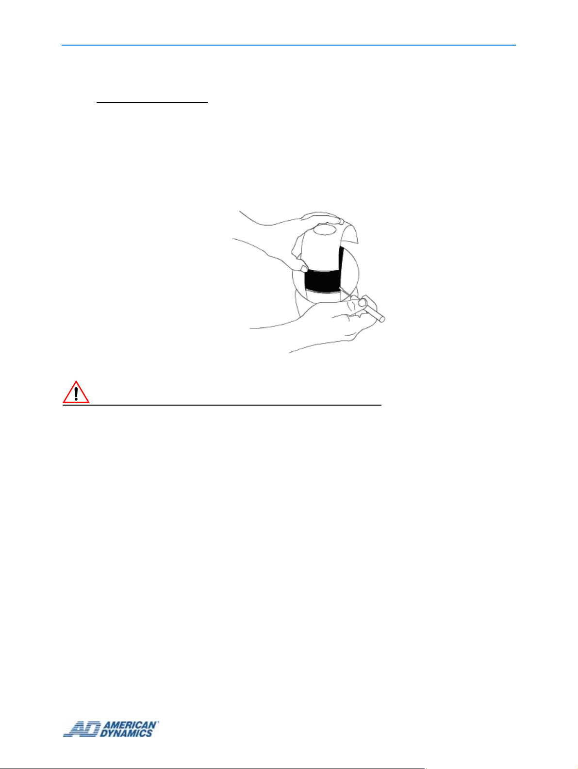
2 Remove pipe elbows (if any), and then make a mark 4cm (1.6in) from the end of the existing
pipe.
Figure 5-2 Marking the pipe ending
3 Slip the cable into the hole of the dust plug and work the plug into the pipe opening.
Note
The plug must be fully inserted and must fully seal the opening.
Figure 5-3 Inserting the dust plug
Note
Thread two setscrews provided into the adapter pipe. Also, to prevent water intrusion, ensure the
adapter pipe has the gasket and rubber seal preinstalled.
5-2
Page 31

Installing IP SDU8 with a ROENDC End Cap
Gasket (seat in groove
at bottom of opening)
Rubber Seal (seat
over opening)
Setscrew (2)
Figure 5-4 Weatherproofing the End Cap assembly
4 Run cables from the existing pipe through the end cap and out its front.
5 Install the end cap as follows:
a Align arrow on the adapter pipe with the mark at the top of the pipe assembly.
Figure 5-5 Aligning the End Cap assembly
b Maintaining arrow/line alignment, insert the End Cap assembly over the pipe until the
rubber sleeve on the adapter pipe meets the circumference mark.
Figure 5-6 Inseting the End Cap assembly
Note
To ensure a good seal on the mounting structure it is recommened that you tighten the setscrews
evenly and do not overtighten them.
c Tighten the two setscre ws using the Allen wrench.
Figure 5-7 T ighting the setscrews
Note
If marks on the pipe of the mounting structure are missing, scribe a circumference mark 4cm
(1.57in) from the end of the pipe.
5-3
Page 32

Installing IP SDU8 with a ROENDC End Cap
Check the level of the pipe assembly. If re-leveling is necessary, loosen the two set screws and
repeat steps a-c above.
Figure 5-8 Checking the pipe assembly’s levels
6 Remove the housing from the packaging.
7 Cut a 30cm (12in) length of Teflon tape.
8 Apply Teflon tape to the threads at the top of the housing .
9 Route the cable from the housing through the bottom opening of the end cap and out its front
as shown in
Figure 5-9.
Figure 5-9 Example of the cable routing through the End Cap assembly
Caution
Take care while you are threading the dome onto the End Cap to avoid any damage to the cables.
10 Twisting the cables to avoid tension, screw the housing onto the adapter pipe.
11 Keep turning the housing until tight.
12 Re-check the level of the dome in the two directions shown in Figure 5-8. Re-level if necessary.
13 Rout e th e pig tail cables fro m th e do m e thr o ug h th e End Cap .
14 Place any excess cable into the end cap, and ensure the O-ring is in place.
15 Using a wrench for tamperproof screws, attach the cover to the End Cap
Figure 5-10 Attaching the End Cap cover
5-4 Installation Guide
Page 33

Installing IP SDU8 with a ROENDC End Cap
At this stage you should prepare the SDU8 Camera for connection to the pendant housing.
Note
The SDU8 Camera’s default physical address is set to 001 and should not need to be changed. If
this address is changed then you should ensure that a record of the new address is kept. During
the software installation ensure the dome configuration address is updated to match the domes
physical address via the Live Video page on the Web GUI in order for camera control to be
maintained. To change the SDU8 physical address, refer to SpeedDome
®
Ultra 8 Camera Dome
Operator’s Guide 8200-0600-01.
16 Gently swivel eyeball to totally expose one of two slot covers.
Figure 5-11 Removing the slot covers
Caution
Swiveling the eyeball fast can damage gears.
17 Insert small, thin-bladed screwdriver into space between cover and eyeball.
18 Gently pry off slot cover.
19 Gently swivel eyeball to totally expose remaining slot cover. With other cover removed, this
cover can be easily removed.
Note
The desiccant bag is only required for outdoor installations. If you are installing in an indoor
position then go to step 18
20 Place the desiccant bag in the pocket located inside the housing and adjacent to the
blower/heater assembly.
5-5
Page 34

Installing IP SDU8 with a ROENDC End Cap
Figure 5-12 Inserting the desiccant bag into the housing
Caution
If the bubble is attached for up to 30 minutes or more and then detached, the bag must be replaced
before the bubble is attached again. An extra bag is supplied. If more are needed, order kit 0352-0207-
02.
21 Connect the housing and eyeball assembly to the base by aligning the Cap and Base tabs.
Base tab
Cap Tab
Figure 5-13 Aligning the Cap and Base tabs
22 Turn the eyeball assembly clockwise until you hear a click.
Figure 5-14 Locking the eyeball assembly
23 Apply power to dome.
5-6 Installation Guide
Page 35

Installing IP SDU8 with a ROENDC End Cap
When power is applied, the dome checks its functionality by performing a homing routine
during which the camera pans and th en either goes to th e st art point of the "apple p eel" p attern
or if powered up once before, to the last position in memory. Once the camera stops, the
camera is online and is ready to be controlled.
Green, Orange, and Yellow LEDs will light in various patterns to indicate status. Typically, you
do not need to view these LEDs unless a failure occurs during or after the routine. See
Diagnostic LED Status Descriptions on page 7-1 for an explanation of the LED patterns.
Once the homing routine completes, affix the bubble to the dome as described in Procedure 5-2.
Attaching the Bubble to the IP SDU8 Unit
Procedure 5-2 describes how to attach the bubble assemb ly to th e ins talled IP SDU8 unit.
Procedure 5-2 Attaching the Bubble to the IP SDU8 Unit
1 Remove the bubble assembly from the package and ensure the bubble is clea n and free of
debris.
2 Attach the coiled lanyard from the bubble to the threaded stud on the indoor housing using the
thumb nut supplied.
Threaded Stud
Coiled Lanyard
Figure 5-15 Coiled lanyard before and after attachment to the housing
3 Attach the bubble assembly.
4 Align the key on the inside of the bubble assembly with the detent on the edge of the housing .
Caution
To maintain the integrity of the gasket seal between the housing flange and the trim ring, do not let the
lanyard get caught between these two pieces as you secure the bubble assembly to the housing.
5-7
Page 36

Installing IP SDU8 with a ROENDC End Cap
Once the bubble is attached to the housing, surface A
Check for bent
flange. Discard
housing if found.
must meet surface B on all sides
not caught between flange and trim ring gasket, or
trim ring and sunshield.
A
. Ensure lanyard is
Check for cracks
in bubble.
Discard bubble if
found.
Figure 5-16 Weatherproofing the IP SDU8
5 Use the drive (taped inside bubble) to tighten the four tamper-proof screws on the bubble
assembly.
6 To compress the gasket evenly, tighten each screw in clockwise formation until slight
resistance is felt, then retighten each screw again in clockwise formation until all screws are
evenly tight.
B
Ensure all four
tamperproof
screws are tight.
Caution
If the network subnet is different from the default camera subnet of 192.168.1.80 then a laptop must be
directly connected to the camera in order to configure the network settings correctly.
7 Refer to the User Guide (8200-0885-02) for instructions on configuring the IP SDU8
configuration settings.
5-8 Installation Guide
Page 37

6 Restoring factory defaults
The IPSDU8 has two physical recessed buttons, a Res et but ton and a Res to re but ton . Re fe r to
Figure 6-1 and Figure 7-1 for the location of the buttons. These buttons are only used during
installation and commissioning of the unit and during fault finding; they are not intended to be used
during normal operation when the camera is installed.
Both buttons have black caps on them. The Reset button is closer to the I/O board and the
Restore button is further from the I/O board.
Note
The restore procedure only resets the web configuration pages to default. To reset the SDU8 to
factory defaults follow the instructions in the SpeedDome
Guide, 8200-0600-01.
View of the board with dome removed
®
Ultra 8 Camera Dome Operator’s
Restore
Button
Reset
Button
Figure 6-1 Reset and Restore buttons
Resetting the IPSDU8
The Reset button, when pressed, will restart the IPSDU8.
Note
Performing a reset will not change any saved configuration settings.
6-1
Page 38

Restoring factory defaults
Restoring factory defaults on the IPSDU8
The Restore button must be used in conjunction with the Reset button to restore the IPSDU8 to
the factory defaults.
Note
The restore procedure only resets the web configuration pages to default. To reset the SDU8 to
factory defaults follow the instructions in the SpeedDome
Guide, 8200-0600-01.
®
Ultra 8 Camera Dome Operator’s
Procedure 6-1 Restoring the IPSDU8 factory defaults
Caution
Loss of configuration
Restoring the factory defaults will result in all saved configuration settings being removed and
the IPSDU8 being restored to the factory settings.
1 Ensure that power is being applied to the IPSDU8 from a power supply.
2 Press and hold the Restore button.
3 Press and release the Reset button.
4 Once the power LED starts flashing rapidly release the Restore button.
5 Refer to the Configuration and User Guide 8200-0885-02 to restore the configuration settings
from a backup configuration file.
6-2 Installation Guide
Page 39

7 Technical Specifications
Diagnostic LEDs
LEDs on the underside of the mounting base enable you to check for power and data .
Video LED
(yellow)
Power LED
(green)
Client LED
(orange)
Figure 7-1 LED Status lights positions
Diagnostic LED Status Descriptions
Power LED (green)
On with repeating slow short flashes off – normal operation.
Rapidly flashing – invalid stored configuration / operating on factory defaults.
Video/Alarm LED (yellow)
Not used at this release to indicate alarm conditions.
Note
Power and Video/Alarm LEDs rapidly flashing together indicates a firmware or configuration
update is in progress.
Client LED (orange)
On – operating normally with one client connected.
7-1
Page 40

Off – operating normally with no clients connected.
Flashing rapidly – network not ready, no IP address assigned.
Note
During the power up process all three LEDs may flash on or off, however if all three LEDs are
flashing together followed by a short delay and the flash sequence repeated, this indicates a
Power On Self Test (POST) error. The number of rapid flashes indicates the actual error code.
Pin Outs for the IP SpeedDome Ultra 8
The following tables give the pin out information for connecting the supplied connectors to the
cabling.
3 wire 24VAC supply
Pin # Color Designation
1 Black 24Vac
2 Red Ground
3 White 24Vac
RJ-45 Ethernet interface (with female to female adaptor)
Pin # Ethernet 10BASE-T 100BASE-TX
1 Transmit 2 Transmit +
3 Receive 4 N/A
5 N/A
6 Receive +
7 N/A
8 N/A
7-2
Page 41

Alarm connector pin-out for Indoor I/O base
Alarm Out Connector is Black and Alarm in is White
Technical Specifications
Figure 7-2 Indoor I/O base alarm connector pin-outs
Alarm connector pin-out for Outdoor I/O base
Alarm Out Connector is Black and Alarm in is White
Figure 7-3 Outdoor I/O base alarm connector pin-out
7-3
Page 42

Technical Specifications
7-4 Installation Guide
 Loading...