

Page 1
SpeedDome® Ultra VII
Camera Dome
Configuration Utility
Operator’s Manual Supplement
RAS915/RAS916/RAS917 Series
About this Supplement
This supplement provides detailed information
about SpeedDome Ultra VII camera dome features
that are not currently covered in your operator’s
manual. This supplements information found in the
following manuals:
• 22x Camera Dome Configuration Utility
Operator’s Manual, 8200-0184-02
• Day/Night Camera Dome Configuration Utility
Operator’s Manual, 8200-0184-04
NOTE: Keep this supplement with your operator’s
manual for reference purposes.
If you need assistance...
Contact your Sales Representative.
New SpeedDome Ultra VII Features
SpeedDome Ultra VII provides the following
features with firmware version 0710-0147-0106
and newer.
Contents
About this Supplement.......................................... 1
New SpeedDome Ultra VII Features..................... 1
Quick Set Menu..................................................... 2
Auto Iris/Auto Focus Resume Setting................... 3
Scan Limits............................................................ 4
AD Up-the-Coax Protocol...................................... 5
SensorNet and RS-422 Matrix Switchers and
Controllers........................................................ 6
Panasonic UTC Protocol Preset Programming..... 9
Specifications-SDU VII........................................ 10
Specifications-22X Camera................................. 11
Specifications-23X Day/Night Camera................ 12
Declarations ........................................................ 13
© 2004 Sensormatic
• Quick Set Menu for accessing commonly used
dome settings
• Auto Iris/Auto Focus resume settings
• Scan Limits for establishing start and stop points
for monitoring a specific area
• AD Up-the-Coax protocol for compatible
American Dynamics controllers
In addition, updated information is provided for the
following:
• SensorNet and RS-422 matrix switchers and
controllers
• Preset programming instructions for the
Panasonic WJ-SX550 multiplexer and
WV-CU550A controller
SPEEDDOME ULTRA VII CAMERA DOME CONFIGURATION UTILITY 8200-0184-09, REV. A
OPERATOR’S MANUAL SUPPLEMENT
1 of 13
Page 2
Quick Set Menu
The Quick Set Menu provides easy access to
commonly used SpeedDome Ultra VII features
when used with compatible controllers. This allows
you to change or activate features without starting
the dome configuration menu. The options on the
Quick Set Menu differ depending on the dome
type. See Figure 1 and Figure 2 for examples of
the different menus.
Figure 1: 22x Camera Dome Quick Set Menu
0 TOGGLE QUICK SET MENU
1 DOME CONFIG MENU
2 AUTO IRIS/AUTO FOCUS
3 FLIP
4 PEEL PATTERN
15 SMOOTH SCAN
16 STEPPED SCAN
17 RANDOM SCAN
20 DOME INFORMATION
Figure 2: Day/Night Camera Dome Quick Set
Menu (2 screens)
0 TOGGLE QUICK SET MENU
1 DOME CONFIG MENU
2 AUTO IRIS/AUTO FOCUS
3 FLIP
4 PEEL PATTERN
10 NIGHT MODE
11 DAY MODE
12 AUTO DAY/NIGHT MODE
13 WDR ON
14 WDR OFF
FOCUS FAR = next page
15 SMOOTH SCAN
16 STEPPED SCAN
17 RANDOM SCAN
20 DOME INFORMATION
To access a feature on the menu, enter the
number and press the Quick Set button (varies by
controller). Table 1 provides a description of the
available options.
Table 1: Quick Set Menu Options
Command Description
0+Quick Set Toggle Quick Set Menu: Toggles
between displaying and hiding
the quick set menu.
1+Quick Set Dome Config Menu: Displays the
SpeedDome Ultra configuration
menu.
2+Quick Set Auto Iris/Auto Focus: Resumes
Auto Focus/Auto Iris mode.
3+Quick Set Flip: Rotates the SpeedDome
180° from its current pointing
direction. This is the same as
pressing the Flip button on
compatible controllers.
4+Quick Set Peel Pattern: Runs the default
Apple Peel Pattern. This is the
same as pressing the Peel button
on compatible controllers.
10+Quick Set* Night Mode: Sets the dome IR
mode setting to ON. The dome
switches to full-time black-andwhite (B/W) mode.
11+Quick Set* Day Mode: Sets the dome IR
mode setting to OFF. The dome
switches to full-time color mode.
12+Quick Set* Auto Day/Night Mode: Re sumes
the most recently selected
automatic IR mode setting.
• Auto High: B/W mode activates
~30 lux.
• Auto Mid: B/W mode activates
~3 lux.
• Auto Low: B/W mode activates
~ 0.5 lux
13+Quick Set* WDR On: Enable s Wid e Dynamic
Range (WDR). Use this setting
when both bright and low light
areas need to be viewed
simultaneously.
FOCUS NEAR = previous page
*
Menu items 10-14 are available on Day/Night
domes only.
SPEEDDOME ULTRA VII CAMERA DOME CONFIGURATION UTILITY 8200-0184-09, REV. A
OPERATOR’S MANUAL SUPPLEMENT
2 of 13
Page 3
Command Description
14+Quick Set* WDR Off: Disables Wide
Dynamic Range (WDR). Use this
setting when the light level is
constant or changes in lighting
conditions are gradual.
15+Quick Set Smooth Scan: Initiates a smooth
scan between the left and right
scan limits, starting at the left
scan limit. If no scan limits have
been set, initiates a smooth 360°
clockwise rotation around the
dome axis using the current tilt,
zoom and focus settings.
16+Quick Set Stepped Scan: Initiates a scan
between the left and right scan
limits pausing briefly every 10° (at
1x zoom), starting at the left scan
limit. When the right scan limit is
reached, the scan is reversed. If
no scan limits have been set,
initiates a clockwise rotation
around the dome axis pausing
briefly every 10° (at 1x zoom) for
3 seconds using the current tilt,
zoom and focus settings.
17+Quick Set Random Scan: Initiates a scan
between the left and right scan
limits pausing randomly between
the limits. If no scan limits have
been set, initiates a clockwise or
counter-clockwise rotation around
the dome axis using the current
tilt, zoom and focus settings. The
dome pauses randomly as it
rotates around the axis.
20+Quick Set Dome Information: Displays the
Dome Information screen
available through the dome
configuration menu.
Refer to your controller manual to determine if the
Quick Set Menu feature is supported. For more
information about these settings, see your
SpeedDome Ultra VII Configuration Utility
Operator’s Manual. See also:
Topic Page
Auto Iris/Auto Focus Resume Setting 3
Scan Limits 4
AD Up-the-Coax Protocol 5
SensorNet and RS-422 Matrix
Switchers and Controllers
6
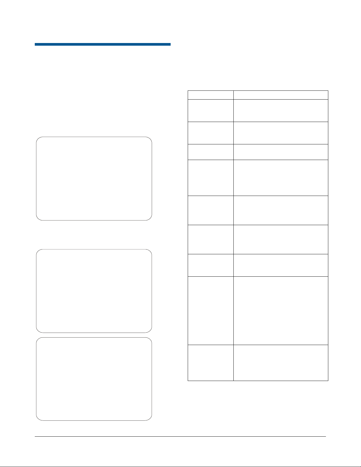
Auto Iris/Auto Focus Resume Setting
Normally, the camera’s iris and focus settings
return to automatic mode when the dome moves a
minimum of one frame from its current pointing
position. In some situations, you may want to
maintain specific iris and/or focus adjustments
based upon your surveillance needs.
Use the I/F Return to Auto setting on the
Pan/Tilt/Zoom/Sync Opts menu to configure the
auto iris and auto focus resume settings.
Figure 3: Pan/Tilt/Zoom/Sync Options menu
PROPORTIONAL FLIP OFF/ON
1ST ZOOM STOP X 33/22
MAX TOTAL ZOOM X 44...242
LINE LOCK ON/OFF
FREEZE FRAME OFF/ON
I/F RETURN TO AUTO OFF/ON/
Four settings are available: On, Off, Iris and Focus.
Setting Description
On Both return to auto iris and return to
auto focus settings are enabled.
Moving the dome resumes auto mode
for both iris and focus changes.
Off Both return to auto iris and return to
auto focus settings are disabled.
Moving the dome does not resume
auto mode for iris and focus changes.
Iris
Focus
Continue with Changing the Auto Iris/Auto Focus
Resume Setting on page 4 to configure the setting.
Only return to auto iris is enabled.
Return to auto focus is disabled.
Moving the dome resumes auto iris
mode without changing focus settings.
Only return to auto focus is
enabled. Return to auto iris is
disabled. Moving the dome resumes
auto focus mode without changing iris
settings.
IRIS/FOCUS
SPEEDDOME ULTRA VII CAMERA DOME CONFIGURATION UTILITY 8200-0184-09, REV. A
OPERATOR’S MANUAL SUPPLEMENT
3 of 13
Page 4
Changing the Auto Iris/Auto Focus Resume Setting
Refer to the SpeedDome Ultra VII Operator’s
Manual for information about displaying menus and
changing settings.
1. Select Pan/Tilt/Zoom/Sync Opts from the
Dome Configuration Menu.
2. Move the highlight bar to I/F Return to Auto.
Change the setting.
• Select On to enable both resume auto iris
and resume auto focus.
• Select Off to disable both resume auto iris
and resume auto focus.
• Select Iris to enable resume auto iris only.
• Select Focus to enable resume auto focus
only.
The default setting is On.
3. Select Exit to return to the Dome Configuration
Menu.
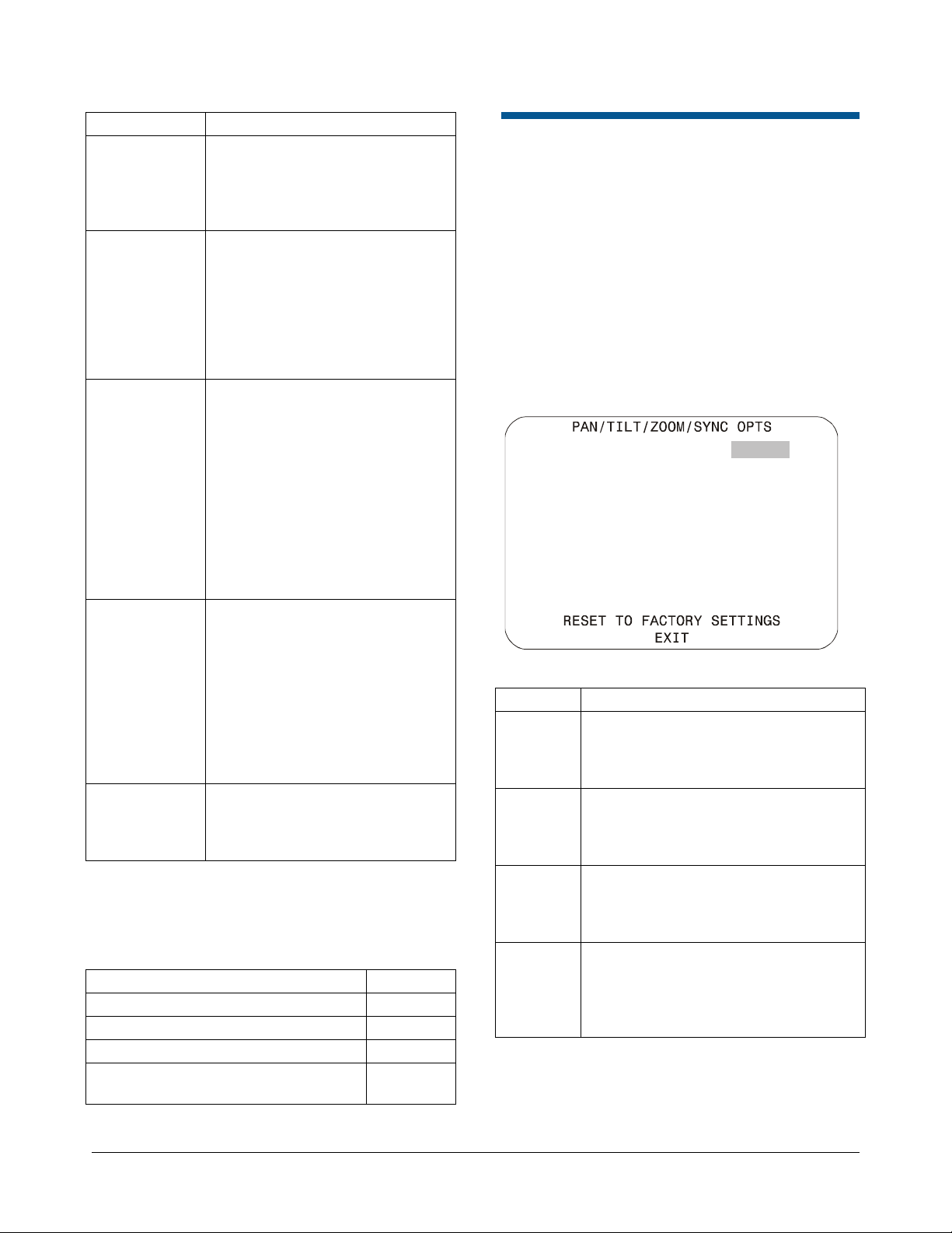
Scan Limits
The dashed circle represents the dome’s field of
view. The solid line curve represents the scan
area. By setting the left and right scan limits where
the building’s wall becomes visible, you ensure that
only useful video of the parking lot is being
observed when the scan is active. Once these
scan limits are programmed you can choose to run
a smooth scan, stepped scan, or random scan.
Table 2: Scan Types
Smooth Scan
An automated scan that slowly
pans between the left and right
scan limits, starting at the left
scan limit. When the right scan
limit is reached, the scan
reverses.
Stepped Scan
An automated scan that pans
slowly pausing briefly every 10°
between the left and right scan
limits. Once the right scan limit
is reached, the scan reverses.
Random Scan
An automated scan that pans
randomly between the left and
right scan limits, starting at any
point between the scan limits.
Scan Limits are two points around the dome’s pan
axis, which define a surveillance area. When
active, the scan repeats until interrupted by a
camera command, preset, pattern, or alarm.
Figure 4 provides an example of scan limits for a
dome installed over the edge of a building
monitoring a parking lot. In this example, the
building blocks part of the dome’s viewable area.
Figure 4: Scan Limits example
Left Scan
Limit
Dome
Building
Right Scan
Limit
If your controller supports the Quick Set menu
function, you can program left and right scan limits
to automate your surveillance activities. The Scan
Limits menu option is found on the Alarms/Areas/
Home/Presets/PZ menu.
Figure 5: Alarms/Areas/Home/Presets/Privacy
Zones menu
ALARMS/AREAS/HOME/PRESETS/PZ
SET ALARM ACTIONS
SET ALARM STATES
SET HOME POSITION
SET NORTH POSITION
AREA BOUNDARIES
PRIVACY ZONES
PRESETS
SCAN LIMITS
EXIT
Continue with Programming Scan Limits on page 5
to configure the setting.
SPEEDDOME ULTRA VII CAMERA DOME CONFIGURATION UTILITY 8200-0184-09, REV. A
OPERATOR’S MANUAL SUPPLEMENT
4 of 13
Page 5

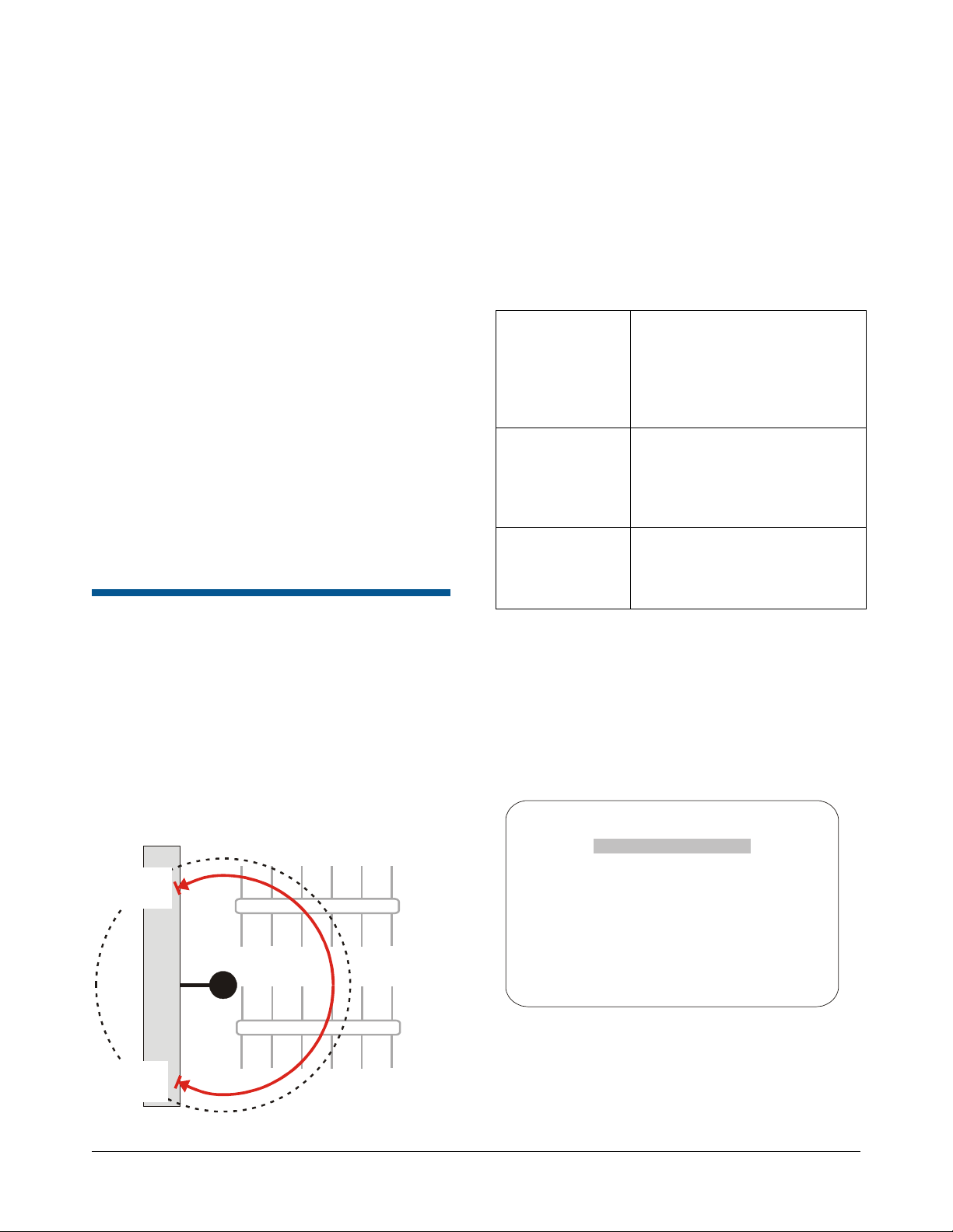
Programming Scan Limits
Refer to the SpeedDome Ultra VII Operator’s
Manual for information about displaying menus and
changing settings.
1. Select Alarms/Areas/Home/Presets/PZ from
the Dome Configuration Menu.
2. Select Scan Limits.
The Scan Limits screen appears:
SCAN LIMITS
PAN to LEFT limit
ZOOM to mark BOUNDARY
Cancel RIGHT limit to Delete
CANCEL
Note: Press Focus during steps 3 or 4 to cancel
scan limit programming.
3. Adjust the pan position of the dome to set the
left scan limit. Press Zoom to select.
4. Pan the dome to the right to set the right scan
limit. Press Zoom to select.
5. When the Alarms/Areas/Home/Presets/PZ
screen appears, select Exit to return to the
Dome Configuration Menu.
AD-UTC Command Summary
Table 3 lists the commands to operate the
configuration utility in AD-UTC environment. The
keyboard must be in programming mode to
perform these functions.
Table 3: Configuration Menu Commands
Command Function
F
, +
(Function, and
then Shift+Menu)
Joystick
(Pan/Tilt)
(Focus Far)
Or
(Focus Near)
(Zoom In) or
Twist joystick
clockwise
(Zoom Out)
or Twist joystick
counterclockwise
F
, +
(Function, and
then Shift+Clear)
Start the configuration utility.
Move the highlight bar on the
active menu.
Select the highlighted item on
the active menu.
Increase the value of the
selected setting.
Display the next choice for the
setting.
Decrease the value of the
selected setting.
Display the previous choice for
the setting.
Save changes and exit the
utility from any screen.
AD Up-the-Coax Protocol
The AD Up-the-Coax (AD-UTC) protocol is a new
protocol developed by American Dynamics. It
provides video and two-way dome control signals
When setting names or entering password
information, the screen displays the available
characters in the selected language. Table 4
provides the name programming and password
entry commands:
on a single cable for compatible American
Dynamics switchers and keyboards.
Note: At the time of publication, the following
American Dynamics keyboards are compatible with
AD-UTC protocol: ADCC0200 and ADCC0300.
The commands provided in this document assume
that one of these keyboards is being used. Contact
your Sales Representative for current information.
Table 4: Name Programming/Password Entry
Commands
Command Function
Joystick
Left/Right
Move the highlight left or right
in the character field.
Joystick Up/Down Move the highlight up or down
in the character field.
(Focus Far)
Or
Select the highlighted
character in the character
field.
(Focus Near)
SPEEDDOME ULTRA VII CAMERA DOME CONFIGURATION UTILITY 8200-0184-09, REV. A
OPERATOR’S MANUAL SUPPLEMENT
5 of 13
Page 6

Command Function
(Zoom In) or
Twist joystick
clockwise
Move the cursor to the right of
the current character in the
name or password.
Move the cursor to the left of
(Zoom Out)
or Twist joystick
the current character in the
name.
counterclockwise
Additional Dome Commands
Table 5 provides the special commands available
when using the dome in an AD-UTC network.
These commands are available when you enter the
keyboard combination provided.
Table 5: Additional Dome Commands
Command Function
F
(Function),
Preset # (1-96), and
then
Preset # (1-96), and
then
F
pattern # (1-3), and
then
(Shift+Preset)
Pattern # (1-3), and
then
Pattern # (1-3), and
then +
(Shift and Preset)
F
(Function+Focus Far)
F
(Function+Focus
Near)
F
(Function+Iris Open)
(Preset)
(Preset)
(Function),
+
F
(Function)
+
Or
+
+
Or
Program selected Preset
Recall selected Preset
Start selected Pattern
programming
Save Pattern programming
Run selected Pattern
continuously
Resume Auto Focus mode
Resume Auto Iris mode
Performance Notes
Keep the following considerations in mind when
using the SpeedDome Ultra VII camera dome in
the AD-UTC environment.
Address Setting
The SpeedDome Ultra VII camera dome must be
set to address 891 to operate in the AD-UTC
environment. When the dome initializes or resets,
the address and protocol information (UTC_T)
appear on-screen.
Accessing the Quick Set Menu
The Quick Set Menu provides easy access to
specific SpeedDome Ultra VII functions from the
keyboard. To access the Quick Set menu, select
the dome, and press
See Quick Set Menu on page 2 for information
about the Quick Set functions.
(Quick Set button).
SensorNet and RS-422 Matrix Switchers and Controllers
The following provides information about
SensorNet and RS-422 controllers compatible with
SpeedDome Ultra VII. Specific operating
considerations are also included.
VM8
Supported Protocol SensorNet
Maximum Presets 0
Maximum Patterns (1) 1
Quick Set Menu Not supported
Address Range 1-8
Notes:
(1) Apple Peel only. Programmable patterns are
not available.
F
+
(Function+Iris Close)
(Flip)
SPEEDDOME ULTRA VII CAMERA DOME CONFIGURATION UTILITY 8200-0184-09, REV. A
OPERATOR’S MANUAL SUPPLEMENT
Rotate dome 180° from current
position (“flip”)
6 of 13
Page 7

VM16/ADTT16 (White Touch Tracker)
Supported Protocol SensorNet
RS-422 (1)
Maximum Presets 96 – SensorNet
4 – RS-422
Maximum Patterns (2) 3
Quick Set Menu Not supported
Address Range 1-16
Notes:
(1) Requires RCSN422 code converter.
(2) Patterns are limited by time and the number of
available dome commands. Total time for each
pattern cannot exceed 6 minutes 50 seconds.
Total dome commands used in all patterns
cannot exceed 99.
VM16E/ADTT16E (Black Touch Tracker)
Supported Protocol SensorNet
RS-422 (1)
Maximum Presets 96 – SensorNet
4 – RS-422
Maximum Patterns (2) 3
Quick Set Menu Yes (3)
Address Range 1-16 or
1-64 (3)
Notes:
(1) Requires RCSN422 code converter.
(2) Patterns are limited by time and the number of
available dome commands. Total time for each
pattern cannot exceed 6 minutes 50 seconds.
Total dome commands used in all patterns
cannot exceed 99.
(3) Requires firmware version 0701-2833-0103
(EEPROM) / 0701-2834-0201 (Flash PROM)
or newer.
VM32/AD32
Supported Protocol SensorNet
RS-422 (1)
Maximum Presets 96 – SensorNet
4 – RS-422
Maximum Patterns (2) 3
Quick Set Menu Not supported
Address Range 1-32
Notes:
(1) Requires RCSN422 code converter.
(2) Patterns are limited by time and the number of
available dome commands. Total time for each
pattern cannot exceed 6 minutes 50 seconds.
Total dome commands used in all patterns
cannot exceed 99.
VM96 (1)
Supported Protocol SensorNet
RS-422
Maximum Presets Unlimited (2)
Maximum Patterns (3) 3
Quick Set Menu Not supported
Address Range 1-32
Notes:
(1) Requires software version 5.2 or newer.
(2) Preset information is stored at the host, not the
dome.
(3) Patterns are limited by time and the number of
available dome commands. Total time for each
pattern cannot exceed 6 minutes 50 seconds.
Total dome commands used in all patterns
cannot exceed 99.
SPEEDDOME ULTRA VII CAMERA DOME CONFIGURATION UTILITY 8200-0184-09, REV. A
OPERATOR’S MANUAL SUPPLEMENT
7 of 13
Page 8

AD2150/AD2350
Supported Protocol RS-422 (1)
Maximum Presets 16 (2) or 60 (3)
Maximum Patterns (4) 3
Quick Set Menu Not supported
Address Range 1-32
Notes:
(1) Requires the AD2083-02 series code converter.
(2) Preset information is stored at the converter, not the
dome.
(3) Requires AD2083-02 with firmware version 0701-
11YB-156A or newer. Preset information is stored in
the dome, not the converter.
(4) Patterns are limited by time and the number of
available dome commands. Total time for each
pattern cannot exceed 6 minutes 50 seconds. Total
dome commands used in all patterns cannot exceed
99.
AD1650
Supported Protocol RS-422 (1)
Maximum Presets 16 (2) or 60 (3)
Maximum Patterns (4) 3
Quick Set Menu Not supported
Address Range 1-128 (5)
Notes:
(1) Requires the AD2083-02 series code converter.
(2) Preset information is stored at the converter, not the
dome.
(3) Requires AD2083-02 with firmware version 0701-
11YB-156A or newer. Preset information is stored in
the dome, not the converter.
(4) Patterns are limited by time and the number of
available dome commands. Total time for each
pattern cannot exceed 6 minutes 50 seconds. Total
dome commands used in all patterns cannot exceed
99.
(5) Requires additional equipment to achieve these
numbers. A dome address within each group of 64
or 99 cameras is reserved as a global broadcast
address.
AD168
Supported Protocol SensorNet (1)
RS-422 (1) or (2)
Maximum Presets
16 (1)(2), 64 (1)(3), or
60 (4)
Maximum Patterns (5) 3
Quick Set Menu Not supported
Address Range SensorNet: 1-180
RS-422: 1-99 (1)(6) or
1-180 (2)(6)
Notes:
(1) Requires the appropriate code control module.
(2) Requires the AD2083-02 series code converter.
(3) Presets information is stored at the converter or
control module, not the dome.
(4) Requires AD2083-02 with firmware version 0701-
11YB-156A or newer. Preset information is stored in
the dome, not the converter.
(5) Patterns are limited by time and the number of
available dome commands. Total time for each
pattern cannot exceed 6 minutes 50 seconds. Total
dome commands used in all patterns cannot exceed
99.
(6) Requires additional equipment to achieve these
numbers. A dome address within each group of 64
or 99 cameras is reserved as a global broadcast
address.
AD2050
Supported Protocol RS-422 (1)
Maximum Presets 16 (2) or 60 (3)
Maximum Patterns (4) 3
Quick Set Menu Not supported
Address Range 1-1024 (5)
Notes:
(1) Requires the AD2083-02 series code converter.
(2) Preset information is stored at the converter, not the
dome.
(3) Requires AD2083-02 with firmware version 0701-
11YB-156A or newer. Preset information is stored in
the dome, not the converter.
(4) Patterns are limited by time and the number of
available dome commands. Total time for each
pattern cannot exceed 6 minutes 50 seconds. Total
dome commands used in all patterns cannot exceed
99.
(5) Requires additional equipment to achieve these
numbers. A dome address within each group of 64
or 99 cameras is reserved as a global broadcast
address.
SPEEDDOME ULTRA VII CAMERA DOME CONFIGURATION UTILITY 8200-0184-09, REV. A
OPERATOR’S MANUAL SUPPLEMENT
8 of 13
Page 9

MegaPower LT
Supported Protocol SensorNet
Maximum Presets 96
Maximum Patterns (1) 3
Quick Set Menu Yes (2)
Address Range 1-32
Notes:
(1) Patterns are limited by time and the number of
available dome commands. Total time for each
pattern cannot exceed 6 minutes 50 seconds. Total
dome commands used in all patterns cannot exceed
99.
(2) Requires a compatible keyboard.
MegaPower 48
Supported Protocol SensorNet
RS-422
Maximum Presets 96(1)
Maximum Patterns (2) 3
Quick Set Menu Yes (3)
Address Range 1-48
Notes:
(1) Preset information is stored at the host, not the
dome.
(2) Patterns are limited by time and the number of
available dome commands. Total time for each
pattern cannot exceed 6 minutes 50 seconds. Total
dome commands used in all patterns cannot exceed
99.
(3) Requires firmware 1.07 or newer and a compatible
keyboard.
MegaPower 1024
Supported Protocol RS-422 (1)
Maximum Presets 16 (2) or 60 (3)
Maximum Patterns (4) 3
Quick Set Menu Not supported
Address Range 1-1024 (5)
(4) Patterns are limited by time and the number of
available dome commands. Total time for each
pattern cannot exceed 6 minutes 50 seconds. Total
dome commands used in all patterns cannot exceed
99.
(5) Requires additional equipment to achieve these
numbers. A dome address within each group of 64
or 99 cameras is reserved as a global broadcast
address.
Panasonic UTC Protocol Preset Programming
The Dome Configuration Menu must be used to
program Presets. Up to 64 Presets may be
programmed using the Panasonic UTC protocol.
These instruction apply to the following equipment:
• Panasonic WJ-SX550 Multiplexer
• Panasonic WV-CU550A Controller
1. Select the monitor and camera number
assigned to the Speed Dome Ultra VII camera
dome.
2. Use the arrow keys on the controller to scroll to
the Camera Setup Menu (D4).
3. Press F1 (On) key to display the Dome
Configuration Menu.
4. Use the joystick to move the highlight to
Alarms/Areas/Home/Presets/PZ. Press Set
to select.
ALARMS/AREAS/HOME/PRESETS/PZ
SET ALARM ACTIONS
SET ALARM STATES
SET HOME POSITION
SET NORTH POSITION
AREA BOUNDARIES
PRIVACY ZONES
PRESETS
SCAN LIMITS
EXIT
Notes:
(1) Requires the AD2083-02 series code converter.
(2) Preset information is stored at the converter, not the
dome.
(3) Requires AD2083-02 with firmware version 0701-
11YB-156A or newer. Preset information is stored in
the dome, not the converter.
SPEEDDOME ULTRA VII CAMERA DOME CONFIGURATION UTILITY 8200-0184-09, REV. A
OPERATOR’S MANUAL SUPPLEMENT
9 of 13
Page 10

5. Use the joystick to move the highlight to
Presets. Press Set to select. The Select
Preset to Program screen displays.
Specifications-Indoor Dome
SELECT PRESET TO PROGRAM
PRESET
NUMBER PRESET NAME
1-96 PRESET 1-96
FOCUS FAR to program preset
EXIT
6. Use the joystick to select the Preset you want
to program. If the Preset has been
programmed the dome automatically moves to
that position.
Move the joystick right to increase the
preset number.
Move the joystick left to decrease the
preset number.
When the correct Preset number appears,
press Set to begin programming.
7. The Presets screen displays. Use the joystick
to adjust the dome to the correct pan/tilt
position.
PRESETS
PRESET X
Position camera with PAN
TILT, ZOOM and IRIS
FOCUS FAR to save and exit
EXIT
IMPORTANT! If using the WV-CU550A
Controller with the WJ-SX550 Multiplexer, you
must press F3 (A. Res) to adjust the zoom,
focus, or iris settings. This places the controller
in normal navigating mode. Make the
necessary adjustments. When finished, press
F1 (On) to resume menu mode.
8. Press Set to save the Preset information.
9. To program more Presets, repeat steps 5
through 8. To exit the Dome Configuration
Menu and save changes, press F4 (Exit).
To verify the Preset programming, enter a Preset
number (1-64) and press Preset.
Operational
Pan/Tilt:
Manual Pan Speed......................... 0.2°-100° per second
(scaled to zoom position)
Manual Tilt Speed........................ 0.25°-100° per second
(scaled to zoom position)
Preset Pan/Tilt Speed............220° per second maximum
Pan Travel.................................. 360° continuous rotation
Tilt Travel ..................................................................>90°
Pan/Tilt Accuracy.....................................................±0.5°
22X Camera Zoom Functions:
Optical Zoom..............................................................22X
Digital Zoom...............................................................11X
Zoom Pause......................................... 22X selectable or
33X default
Total Zoom...............................................................242X
Maximum Zoom Stop.......44X, 66X, 88X (default), 110X,
132X, 154X, 176X, 198X, 220X, 242X
Zoom/Focus Accuracy ...........................................±0.5%
23x Day/Night Camera Zoom Functions:
Optical Zoom..............................................................23X
Digital Zoom...............................................................10X
Zoom Pause......................................... 23X selectable or
35X default
Total Zoom...............................................................230X
Maximum Zoom Stop.......46X, 69X, 92X (default), 115X,
138X, 161X, 184X, 207X, 230X
Zoom/Focus Accuracy ...........................................±0.5%
Auto Synchronization:
Line Locked.........................Remote V-phase adjustment
Internal..........................................Built-in sync generator
Address Range .......................................................1-255
Number of Presets:
VM16 / ADTT16 ...........................96 with SensorNet 485
VM32 / AD32................................96 with SensorNet 485
AD2150............................................. 64 with Manchester
16 with RS422 (using AD2083-02A)
VM96......................Virtual with RS422 or SensorNet 485
VM168 / AD168................................ 64 with Manchester,
RS-422 or SensorNet
16 with RS422 (using AD2083-02A)
AD2050............................................. 64 with Manchester
16 with RS422 (using AD2083-02A)
SPEEDDOME ULTRA VII CAMERA DOME CONFIGURATION UTILITY 8200-0184-09, REV. A
OPERATOR’S MANUAL SUPPLEMENT
10 of 13
Page 11

Quick View™ Access Time............<1 second to position.
Full zoom in <4 seconds.
Focus on VM16, VM32 and
VideoManager systems is <1 second.
Focus on VM96 and RV2715 systems
is <7 seconds
Programmable Patterns
Number Patterns.............................................................3
Storage
Program Storage ................256 Kbytes of Flash memory
Data Storage .................................. 128 Kbytes of SRAM
Configuration Menu
Languages................English, French, German, Spanish,
Italian, and Portuguese
Electrical
Input Voltage ....................................18-30Vac, 50/60 Hz
UL Class 2 LPS
Design Tolerance..............................16-36Vac, 50/60 Hz
Power Consumption ........................................ 16W max.
Current........................................................... 0.85A max.
Allowable Drop Out................................................100ms
Power On In-Rush Current.......................................1.5A
Surge Protection:
Video Output................................Low capacitance Zener
suppressor 6.5V, 1500W
Power Line..........................TVS rated at 60V, 1.5 joules,
250A 8/20µs impulse
RS422............................................TVS rated at 9.8V/1A,
20V/25A, 500W,
8/20µs impulse
Manchester/
SensorNet 485.................... Gas discharge tube rated at:
8/20µs impulse discharge current
of 10kA, ten 8/20µs impulse
discharge current of 5kA
Isolation transformer coupled 2000Vrms
PTC fuse protects transformer.
TVS rated at 9.8V/1A, 20V/25A,
500W, 8/20µs impulse
Alarm Input ....................................TVS rated at 9.8V/1A,
20V/25A, 500W, 8/20µs impulse
Alarms Inputs/Control Outputs:
When no I/O board is used:
Inputs........................................ 1 dry contact/3.5mA sink
Outputs......................................... 1 open collector driver
@ 12Vdc, 40mA
When I/O board is used:
Inputs......................................4 dry contacts/3.5mA sink
Outputs ....................................... 4 open collector drivers
@ 12Vdc, 40mA
Environmental
Operating Temperature........ –10° to 50°C (14° to 122°F)
Relative Humidity.....................0 to 95% non-condensing
Storage Temperature................................ –20°C to 65°C
(–4°F to 149°F)
Mechanical
Height.............................................................20.8cm (8")
Eyeball Diameter............................................12cm (4.7")
Weight:
Housing and Eyeball.............................. 1.36kg (3 lbs.)
Base (standard)................................ 0.09kg (0.20 lbs.)
Base (with I/O board)........................ 0.16kg (0.35 lbs.)
Lens and Bubble Densities
Eyeball Lens ......................................................... f0
Bubbles:
RUCLR (Clear) ..................................................f0
RUSLV (Silver) .......................................f1.5 to f2
RUSMK (Smoke)............................................f0.5
RUGLD (Gold)........................................f1.5 to f2
Specifications-22X Camera
Type.............................. Interline transfer 1/4" CCD array
Scanning Area..................................3.2 (H) x 2.4 (V) mm
Scanning System..........................................2:1 interlace
Video Out............................1.0 Vp-p/75 ohms composite
Signal-to-Noise..........................................50 dB (typical)
Color Camera Only
Horizontal Resolution..........................470 lines at center
Minimum Illumination ...............0.3 lux (AGC On, 20 IRE)
0.02 lux with ¼ s open shutter
White Balance............................Through-the-Lens (TTL)
Automatic Tracing White balance (ATW)
NTSC:
Effective Pixels............................768 (H) x 494 (V) pixels
Scanning...........................525 lines, 60 fields, 30 frames
Horizontal........................................................15.734kHz
Vertical..................................................................59.9Hz
SPEEDDOME ULTRA VII CAMERA DOME CONFIGURATION UTILITY 8200-0184-09, REV. A
OPERATOR’S MANUAL SUPPLEMENT
11 of 13
Page 12

PAL:
Effective Pixels ...........................752 (H) x 582 (V) pixels
Scanning...........................625 lines, 50 fields, 25 frames
Horizontal ....................................................... 15.625kHz
Vertical..................................................................... 50Hz
Monochrome Camera Only
Horizontal Resolution.......................... 500 lines at center
Minimum Illumination........... 0.008 lux (AGC On, 20 IRE)
0.004 lux with ¼ s open shutter
White Balance ........................... Through-the-Lens (TTL)
Automatic Tracing White balance (ATW)
Minimum Illumination ........0.5 lux (AGC On, 20 IRE)
0.03 lux with ¼ s open shutter
0.01 lux in IR mode
0.009 lux in IR mode with ¼ s open shutter
White Balance................... Through-the-Lens (TTL)
Automatic Tracing
White balance (ATW)
NTSC:
Effective Pixels............................724 (H) x 494 (V) pixels
Scanning...........................525 lines, 60 fields, 30 frames
Horizontal........................................................15.734kHz
Vertical..................................................................59.9Hz
EIA:
Effective Pixels ...........................768 (H) x 494 (V) pixels
Scanning...........................525 lines, 60 fields, 30 frames
Horizontal ....................................................... 15.734kHz
Vertical.................................................................. 59.9Hz
PAL:
Effective Pixels............................724 (H) x 582 (V) pixels
Scanning...........................625 lines, 50 fields, 25 frames
Horizontal........................................................15.625kHz
Vertical.....................................................................50Hz
CCIR:
Effective Pixels ...........................752 (H) x 582 (V) pixels
Scanning...........................625 lines, 50 fields, 25 frames
Horizontal ....................................................... 15.625kHz
Vertical..................................................................... 50Hz
Lens Design
Type........................................................Aspherical
Focal Length.....................................3.6 to 82.8mm
Aperture........................................ f1.6 (wide angle)
f3.7 (telephoto)
Lens Design
Type.........................................................Aspherical
Focal Length........................................... 4 to 88mm
Aperture.........................................f1.6 (wide angle)
Viewing Angle (equivalent to 8-80 mm on 1/2" CCD
array, or 11-110 mm on 2/3" CCD array):
3.6mm....................................... 54.0°(H) x 40.5°(V)
82.8mm......................................... 2.5°(H) x 1.9°(V)
f3.8 (telephoto)
Viewing Angle (equivalent to 8-80 mm on 1/2" CCD
array, or 11-110 mm on 2/3" CCD array):
4mm...........................................47.0°(H) x 35.2°(V)
88mm.............................................2.2°(H) x 1.6°(V)
Specifications-23X Day/Night Camera
Type...............................Interline transfer 1/4" CCD array
Scanning Area.................................3.2 (H) x 2.4 (V) mm
Scanning System.......................................... 2:1 interlace
Video Out............................1.0 Vp-p/75 ohms composite
Signal-to-Noise..........................................50 dB (typical)
Horizontal Resolution.......................... 470 lines at center
Field-of-View Formulas:
3.2mm* x distance from camera (m)
Focal length (mm)
2.4mm** x distance from camera (m)
Focal length (mm)
* Horizontal scanning area of pickup device (mm) in camera.
** Vertical scanning area of pickup device (mm) in camera.
Example: Wide angle view with lens at 6mm and viewed
object at 10m.
3.2mm x 10m
6mm
2.4mm x 10m
6mm
= 5.33m Horizontal view (m)
= 4.0m Vertical view (m)
= Horizontal view (m)
= Vertical view (m)
SPEEDDOME ULTRA VII CAMERA DOME CONFIGURATION UTILITY 8200-0184-09, REV. A
OPERATOR’S MANUAL SUPPLEMENT
12 of 13
Page 13

t
Declarations
Regulatory Compliance
Emissions ................................ 47 CFR, Part 15, Class A
ICES-003
EN55022, Class B
EN61000-3-2
EN61000-3-3
AS/NZ 3548, Class A
CISPR 22
Immunity........................................................ EN50130-4
Safety ..................................................................UL1950
CSA C22.2 No. 950
EN60950
IEC 60950
FCC COMPLIANCE: This equipment complies with Part 15
of the FCC rules for intentional radiators and Class A digital
devices when installed and used in accordance with the
instruction manual. Following these rules provides reasonable
protection against harmful interference from equipment
operated in a commercial area. This equipment should not be
installed in a residential area as it can radiate radio frequency
energy that could interfere with radio communications, a
situation the user would have to fix at their own expense.
EQUIPMENT MODIFICATION CAUTION: Equipment
changes or modifications not expressly approved by
Sensormatic Electronics Corporation, the party responsible for
FCC compliance, could void the user's authority to operate the
equipment and could create a hazardous condition.
Other Declarations
Thank you for using American Dynamics products. We
support our products through an extensive and worldwide
network of dealers. The dealer, through whom you originally
purchased this product, is your point of contact if you have a
need for service or support. Our dealers are fully empowered
to provide the very best in customer service and support.
Dealers should contact American Dynamics at
(800) 507-6268 or (561) 912-6259 or on the web at
www.americandynamics.net.
WARRANTY DISCLAIMER: Sensormatic Electronics
Corporation makes no representation or warranty with respect
to the contents hereof and specifically disclaims any implied
warranties of merchantability or fitness for any particular
purpose.
NOTICE: The information in this manual was current when
published. The manufacturer reserves the right to revise and
improve its products. All specifications are therefore subject to
change without notice.
LIMITED RIGHTS NOTICE: For units of the Department
of Defense, all documentation and manuals were developed at
private expense and no part of it was developed using
Government Funds. The restrictions governing the use and
disclosure of technical data marked with this legend are set
forth in the definition of “limited rights” in paragraph (a) (15)
of the clause of DFARS 252.227.7013. Unpublished - rights
reserved under the Copyright Laws of the United States.
TRADEMARK NOTICE: American Dynamics, Sensormatic,
and SpeedDome are trademarks or registered trademarks of
Sensormatic Electronics Corporation. Other product names
mentioned herein may be trademarks or registered trademarks
of Sensormatic or other companies.
COPYRIGHT: Under copyright laws, the contents of this
manual may not be copied, photocopied, reproduced,
translated or reduced to any electronic medium or machinereadable form, in whole or in part, without prior written
consent of Sensormatic Electronics.
BSL 01/2004
www.americandynamics.ne
SPEEDDOME ULTRA VII CAMERA DOME CONFIGURATION UTILITY 8200-0184-09, REV. A
OPERATOR’S MANUAL SUPPLEMENT
13 of 13
 Loading...