

Page 1
Tyco Illustra Pro 5MP
Thermal Elevated Skin
Temperature Detection Camera
Installation and Configuration Guide
Page 2

Notice
Please read this manual thoroughly and save it for future use before attempting to connect or operate
this unit.
The information in this manual was current when published. The manufacturer reserves the right to
revise and improve its products. All specifications are therefore subject to change without notice.
Copyright
© 2020 Johnson Controls. All rights reserved.
JOHNSON CONTROLS, TYCO and ILLUSTRA are trademarks and/or registered trademarks.
Unauthorized use is strictly prohibited.
Tyco Security Products
6600 Congress Avenue
Boca Raton, FL 33487 U.S.A.
Customer Service
Thank you for using Illustra products. We support our products through an extensive worldwide
network of dealers. The dealer through whom you originally purchased this product is your point of
contact if you need service or support. Our dealers are empowered to provide the very best in
customer service and support. See https://illustracameras.com/technical-support/ for all contact
details.
Trademarks
The trademarks, logos, and service marks displayed on this document are registered in the United
States [or other countries]. Any misuse of the trademarks is strictly prohibited and Tyco Security
Products will aggressively enforce its intellectual property rights to the fullest extent of the law,
including pursuit of criminal prosecution wherever necessary. All trademarks not owned by Tyco
Security Products are the property of their respective owners, and are used with permission or
allowed under applicable laws.
Product offerings and specifications are subject to change without notice. Actual products may vary
from photos. Not all products include all features. Availability varies by region; contact your sales
representative.
Page 3

Table of Contents
Warning 6
Overview 8
Tyco Illustra Pro 5MP Thermal Elevated Skin Temperature Detection Camera 9
Product overview 9
Installation 9
Calibration / accuracy 16
Guidelines 16
Factors to consider for the environment and installation that can impact measurement 17
Network Topology 20
Network Connection 21
Default IPAddress 21
DHCP 22
Live View 24
Face DetectionView 26
Search 27
Configuration 31
Image 33
DisplaySettings 33
Video / Audio 35
On Screen Display(OSD) 37
Video Mask 38
Region of Interest (ROI) Configuration 38
Temperature 39
Temperature measurement 39
Temperature measurement schedule 41
Temperature Calibration 43
DisplaySettings 45
Alarm and Event 46
Motion Detection 46
Page 4

Tyco Illustra Pro 5MP Thermal Elevated Skin Temperature Detection Camera Installation and Configuration
Anomaly 48
Alarm In 49
Alarm Out 50
Alarm Server 50
Audio Alarm 51
Light Alarm 51
Exception 52
Line Crossing 53
Intrusion 55
Face Detection 57
Target Counting 59
Security 62
User 62
Online User 63
Blockand Allow lists 64
Security Management 64
Network 66
TCP/IP 66
Ports 68
Server 68
DDNS 68
IEEE 802.1X 69
RTSP 69
Multicast 70
UPnP Discovery 71
E-mail 71
FTP 72
HTTPS 73
SPVMN 74
Qualityof Service (QoS) 75
Maintenance 76
Backup and Restore 76
8200-1953-09 A0 4
Page 5

Reboot 77
Upgrade 77
Log 78
System 79
BasicInformation 79
Date and Time 79
Local Config 80
Storage 82
Config 82
Download 84
Appendix A - Shutdown Procedure 85
Appendix B: Using Media Player to View RTSP Streaming 86
Appendix C: Technical Specifications 87
Appendix D - Manufacturer and Local Contact Information 92
Disclaimer and Regulatory 94
Disclaimer 94
Regulatory Information 94
EMC Information 96
End User License Agreement (EULA) 101
5 8200-1953-09 A0
Page 6

Warning
• This product is intended to be supplied by a Listed Power Unit, marked with 'Limited Power
Source', 'LPS' on unit, output rated minimum 12V/2 A or POE 48V/ 350mA or AC24V
(depending on models), no more than 2000m altitude of operation and Tma=60 Deg.C.
• Do not attempt to disassemble the camera; in order to prevent electric shock, do not
remove screws or covers.
• This product requires professional installation by a service technician with the appropriate
training and experience necessary to ensure proper installation and configuration for the
applicable operating environment and usage case to ensure the safe and accurate operation
of the product.
• There are no user-serviceable parts inside. Please contact the nearest service center as
soon as possible if there is any failure.
• Avoid shock, vibration and heavy pressing which can cause damage to the product.
• Do not use corrosive detergent to clean main body of the camera. If necessary, please use
soft dry cloth to wipe dirt; for hard contamination, use neutral detergent. Any cleanser for
high grade furniture is applicable.
• Do not operate it in case temperature, humidity and power supply are beyond the limited
stipulations.
• The thermal camera shall be used in a stable indoor environment without wind. Please
ensure the monitoring field is far away from objects that could produce airflow, high
temperature and reflection. Please do not install opposite to a door, air conditioner or any
place in sunshine.
• Please put up a tent or build a closed environment to ensure the accuracy for outdoor
installation.
• Please make sure the blackbody is installed opposite to the camera (where the camera can
see it).
• Avoid backgrounds that are too crowded or bright.
• This manual is for using and managing the product. We may reserve the rights of amending
the typographical errors, inconsistencies with the latest version, software upgrades and
product improvements, interpretation and modification. These changes will be published in
the latest version without special notification.
• Multiple Faces usage does not comply with IEC 80601-2-59.
6 8200-1953-09 A0
Page 7
Tyco Illustra Pro 5MP Thermal Elevated Skin Temperature Detection Camera Installation and Configuration
Table 1 Symbols table
The following symbols are found on the camera’s product label
Refer to instruction manual or booklet
Earth (ground)
Separate collection for electrical and electronic equipment
Complies with provisions of Directive 93/68/EEC
Note:Symbols and required information on the product label are legible at 0.75 meter (2.46 feet).
8200-1953-09 A0 7
Page 8

Overview
This Tyco Illustra Pro 5MP Thermal Elevated Skin Temperature Detection camera Installation and
Configuration Guide is a user manual which provides installation, and configuration information of the
camera in Table 2 on Page 8.
Table 2 Product codes
Sales Bundle
Code
IPT05-B29-BNDA3 IPT05-B29-BIA3
IPT05-B29-BN2A3 IPT05-B29-BIA3
Camera
Product Code
The Tyco Illustra Pro 5MP Thermal Elevated Skin Temperature Detection camera is specially
designed to detect human body temperature with high accuracy in real time. This series of product
supports real-time temperature measurement, face capture, smart event detection and alarm
linkages. It can help you discover abnormal body temperature of people entering and exiting and other
unexpected events immediately and protects you from property loss.
It can be used for preliminary temperature measurement in office buildings, factories, stations,
airports and other public places compared to other visible light cameras.
Main Features
Model Name Description
Tyco Illustra Pro
Thermal Elevated
Skin Temperature
Detection Cameral,
5MP, 8mm
Tyco Illustra Pro
Thermal Elevated
Skin Temperature
Detection Cameral,
5MP, 8mm
Tyco Illustra Pro Thermal Elevated Skin Temperature Detection Camera camera, Visible/Thermal, 5MP/384*288, 8mm/12mm,
20M IR, sound-light alarm, Alarm/Audio,
Micro SD, DC/PoE, IP40, with additional
indoor 110V Blackbody
Tyco Illustra Pro Thermal Elevated Skin Temperature Detection Camera, Visible/Thermal,
5MP/384*288, 8mm/12mm, 20M IR, soundlight alarm, Alarm/Audio, Micro SD, DC/PoE,
IP40, with additional indoor 220V Blackbody
Temperature Measurement
• Temperature measurement range: 30~42°C (86~107.6°F)
• Temperature accuracy: ±0.3°C
• Three GUI view modes: optical and thermal image, optical image, thermal image.
• Audio and light alarm linkage.
Intelligent Analytics
• Abnormal video signal detection: including scene blur detection, video blur detection,
video color cast detection.
• Perimeter Alert: Line crossing detection (human/motor vehicle/non-motor vehicle
classification), Region intrusion/entrance/exiting detection (human/motor vehicle/nonmotor vehicle classification.
• Target Counting: line crossing people/motor vehicle/non-motor vehicle counting.
• Face detection: face capture, face detection.
• Audio and light alarm linkage.
8 8200-1953-09 A0
Page 9

Tyco Illustra Pro 5MP Thermal Elevated Skin Temperature Detection Camera Installation and Configuration
Tyco Illustra Pro 5MP Thermal Elevated Skin
Temperature Detection Camera
This chapter provides general quick start guide information on the camera and installation
procedures.
Product overview
This chapter included the quick start information guide information and installation procedure of the
Tyco Illustra Pro 5MP Thermal Elevated Skin Temperature Detection Camera. Product codes and
description of the camera is provided in the table below.
Table 3 Product code and description of the Tyco Illustra Pro 5MP Thermal Elevated Skin
Temperature Detection camera
Sales Bundle
Code
IPT05-B29-BNDA3
IPT05-B29-BN2A3 IPT05-B29-BIA3
Camera
Product Code
IPT05-B29-BIA3
Installation
In the box
Check everything in the packing box matches to the order form and the packing slip. In addition to
this guide, items below are included in the packing box:
• 1 x Camera
• 4 x PA 4x25mm screws
• 4 x plastic screw anchors
• 1 x PW 3x5mm machine screw
Description
Tyco Illustra Pro Thermal Elevated Skin Temperature Detection
Camera camera, Visible/Thermal, 5MP/384*288, 8mm/12mm, 20M
IR, sound-light alarm, Alarm/Audio, Micro SD, DC/PoE, IP40, with
additional indoor 110V Blackbody
Tyco Illustra Pro Thermal Elevated Skin Temperature Detection
Camera, Visible/Thermal, 5MP/384*288, 8mm/12mm, 20M IR,
sound-light alarm, Alarm/Audio, Micro SD, DC/PoE, IP40, with additional indoor 220V Blackbody
• 4 x 4x10mm screws
• 1 x L-key hexagonal wrench
• 1 x Mounting template
• 1 x Camera adaptor plate
• 1 x Hexagonal wrench
• 1 x Blackbody device
• 1 x Quick Start Guide
8200-1953-09 A0 9
Page 10
• 2 x Ferrite clamps
Contact your dealer if any item is missing.
Installation Tools
• 1 x Screwdriver
• 1 x L-Key hexagonal wrench
Quick Reference
• Default IP: 192.168.1.168 (DHCP enabled)
• Default Username and Password: admin / admin
• Power: 12VDC, 2A; PoE 48VDC, 0.35A
• Use Internet Explorer 11 web browser
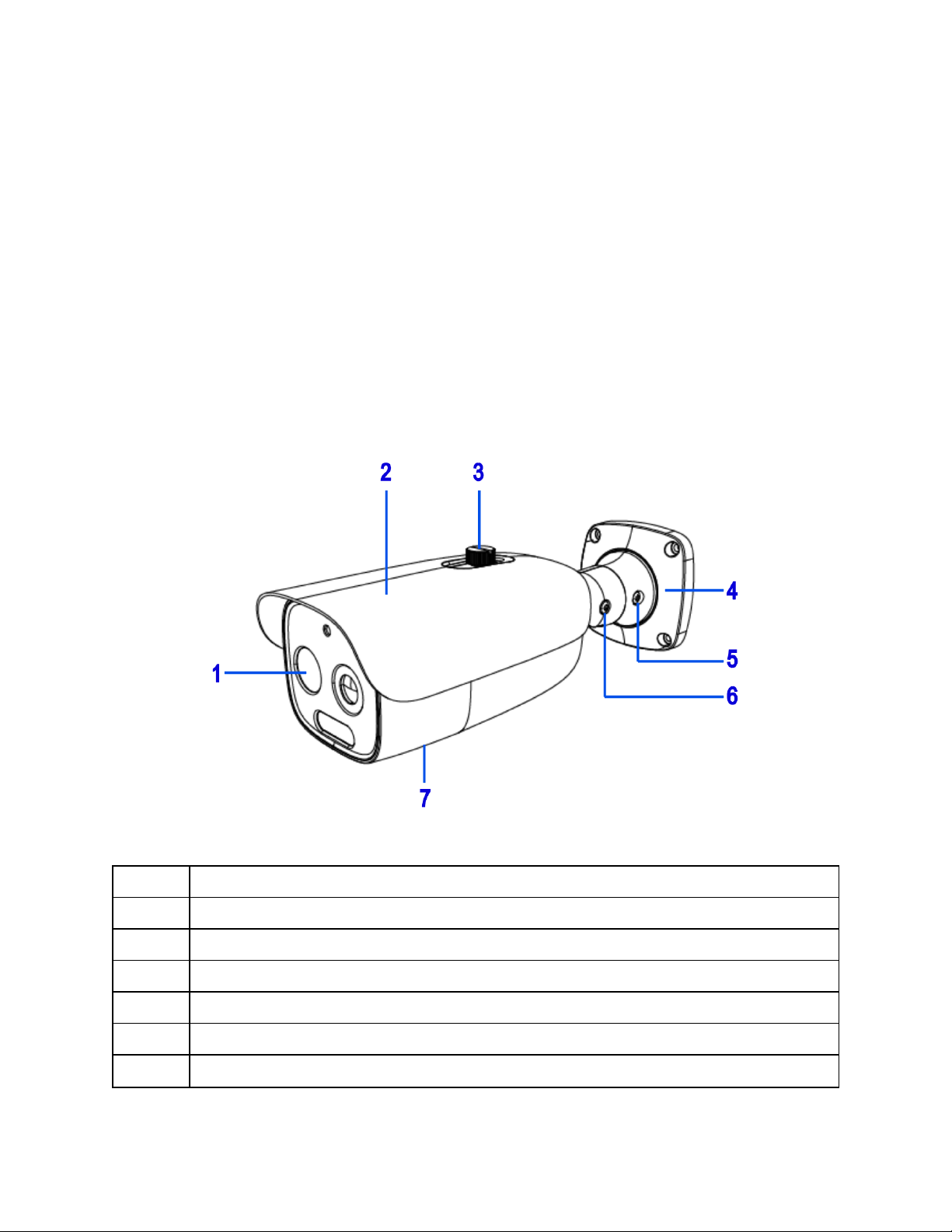
Figure 4 Tyco Illustra Pro 5MP Thermal Elevated Skin Temperature Detection Camera parts
Table 5 Camera part descriptions
Number Camera part description
1 Camera lens
2 Sun shield cover
3 Sun shield cover adjustment thumb-screw
4 Camera base
5 Pan adjustment connection
6 Tilt adjustment connection
10 8200-1953-09 A0
Page 11
Tyco Illustra Pro 5MP Thermal Elevated Skin Temperature Detection Camera Installation and Configuration
7
Camera body (Camera buttons and SD card slot are located on the underside of the camera).
Note: You will need to remove the cover to access them.
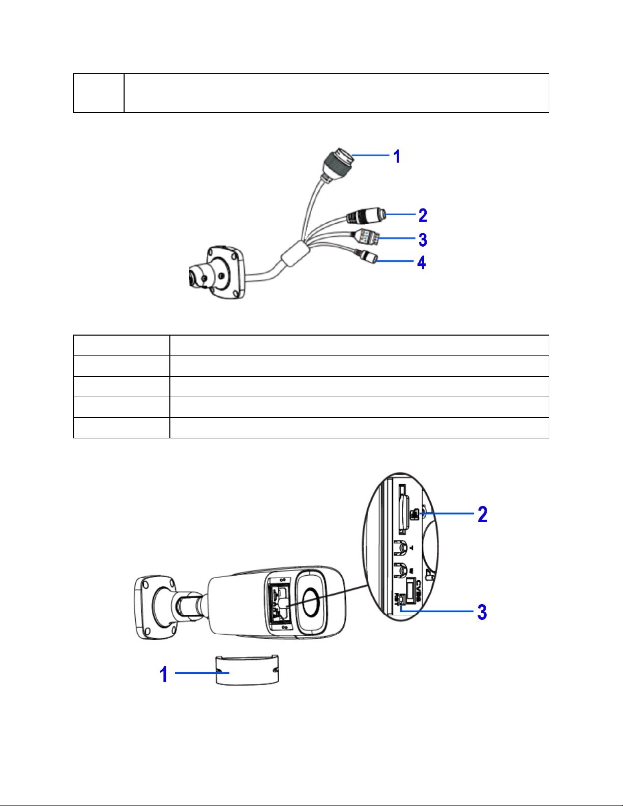
Figure 6 Cable connections
Table 7 Cable connection descriptions
Number Cable connection description
1 Ethernet connector and also supports PoE
2 Audio Input (Max 30V DC / 30mA)
3 Alarm Output / input (5 V DCV @ 10mA)
4 Power connector (12 V DCV @ 1mA)
Figure 8 Camera buttons and SD card slot
8200-1953-09 A0 11
Page 12
Note:Remove the two screws on the camera cover (1) (Figure 7) to access the
buttons. Securely attach the cover when finished.
Table 9 Camera button descriptions and SD card slot
Number Cable connection description
1 Camera button cover
2 Micro SD Card Slot
3 Reset (Hold for more than 3 seconds)
Procedure 1 Mounting the camera to a wall or ceiling
1 Place the mounting template on the surface that you want to attach the camera.
2 On the surface drill four Ø 5mm holes and cut out a >30 Ø mm cable hole as per the
markings identified on the mounting template.
3 Securely place the four screw anchors into the four holes.
4 Place the camera cable through the cable hole on the mounting surface.
5 Hold the camera base (4) (Figure 4) up to the mounting template and align the four holes on
the camera base with the four holes on the mounting surface.
6 Insert the four PA4x25mm screws into the four holes on the camera base and securely
attach the camera to the mounting surface.
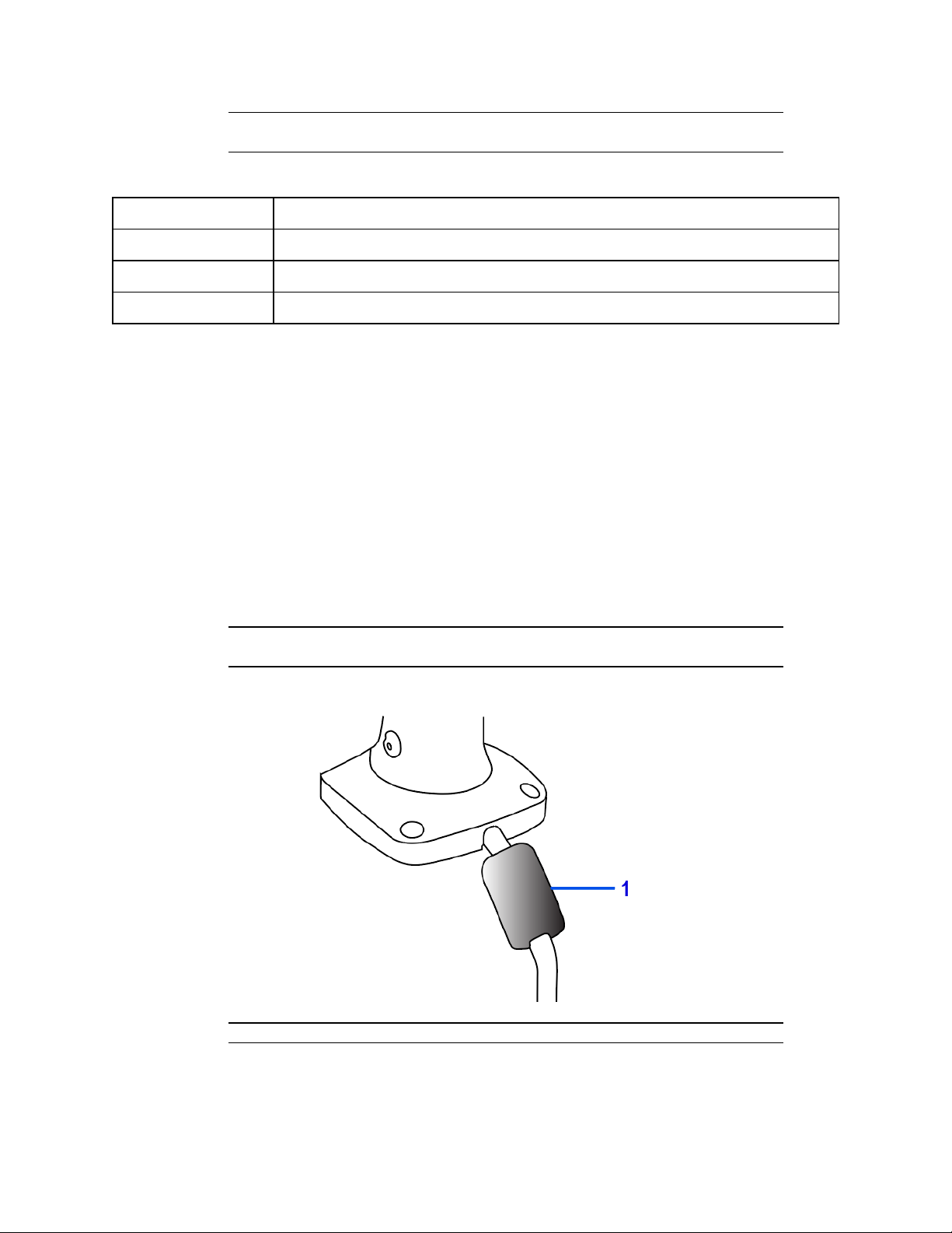
7 Attach the ferrite ‘round clamp’ to the large single camera cable.
Note:Ensure that the ferrite clamp (1) (Figure 10) is positioned close to the camera
base on the cable.
Figure 10 Round ferrite clamp position on the cable
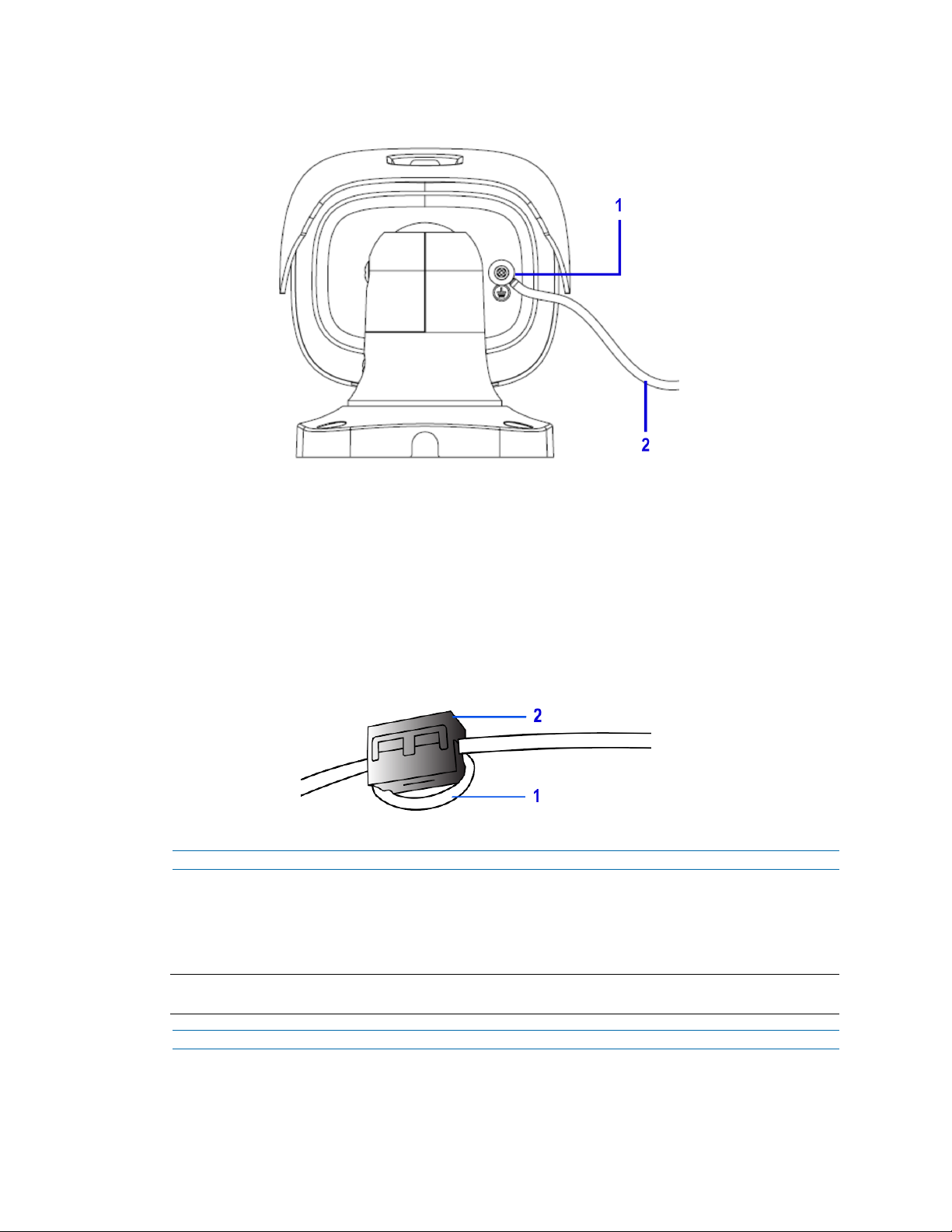
Note:The camera must be connected to earth ground
8 Attach a ring-type terminal to the end of the ground wire (2) (Figure 11) (not provided). Insert
the machine screw through the ring terminal and attach to the camera (1) (Figure 11).
12 8200-1953-09 A0
Page 13
Tyco Illustra Pro 5MP Thermal Elevated Skin Temperature Detection Camera Installation and Configuration
Figure 11 Earth wire connection
9 To power up the camera:
• connect a 12V DC power supply to the power connector on the camera
cable
OR
• connect a shielded PoE cable to the ethernet / PoE slot on the camera
cable. Note: You must first attach the ferrite ‘rectangle clamp’ around
the Ethernet cable (1) (Figure 12). The cable (1) (Figure 12) must loop
around the clamp (2) (Figure 12) before the clamp is enclosed.
Figure 12 Cable looped inside the ferrite clamp
- End -
Procedure 2 Adjusting the sun shield
1 Loosen the thumb-screw (3) (Figure 4) to move the sun shield cover forward and backward
over the camera body.
Note:You must securely lock the thumb screw to ensure that the sun shield cover holds the modified
position.
- End -
Procedure 3 Adjusting the camera position
1 Use the L-key hexagonal wrench to:
8200-1953-09 A0 13
Page 14
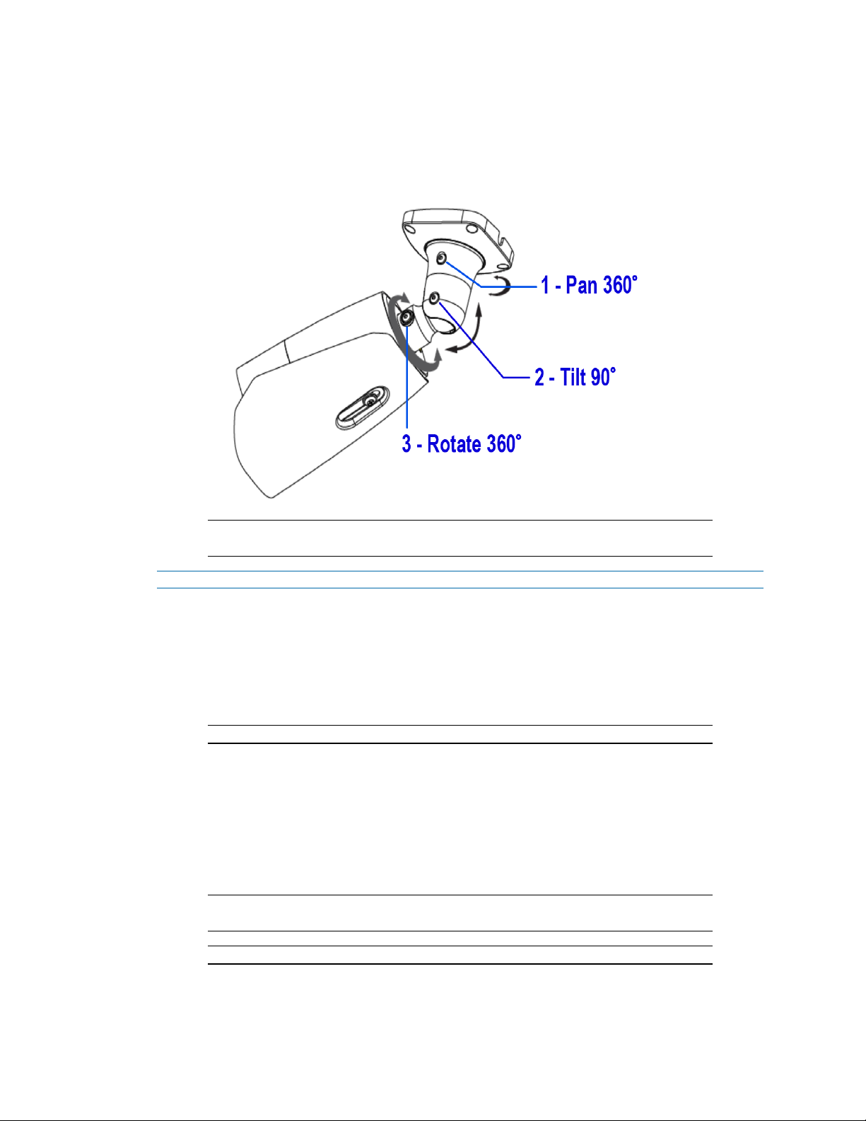
a Unlock the screw (1) (Figure 13) and pan the camera field of view up to 360 degrees.
b Unlock the screw (2) (Figure 13) to tilt the camera body up to 90 degrees.
c Unlock the screw (3) (Figure 13) and rotate the camera body up to 360 degrees.
Figure 13 Pan, tilt and rotate screws
Note:You must securely lock each screw to ensure that the camera holds the
modified position.
- End -
Procedure 4 Mounting the camera to a tripod stand
1 Install the tripod as per the instructions that come with it.
2 Align the four holes on the camera adaptor plate with the four holes on the camera base and
insert the four 4x10mm screws into the four holes and securely attach the camera adaptor
plate to the camera base.
Note:The camera is now attached to the camera adaptor plate.
3 Place the camera adaptor plate on top of the tripod stand and align the 1/4 “ threaded screw
connection underneath the camera adaptor plate with the threaded screw on the tripod
stand.
4 Rotate the camera adaptor plate to securely attach it to the tripod stand.
5 Insert all camera cables through the cable side entry notch on the camera base.
6 Attach the ferrite ‘round clamp’ to the large single camera cable.
Note:Ensure that the ferrite clamp (1) (Figure 10) is positioned close to the camera
base on the cable.
Note:The camera must be connected to earth ground.
7 Attach a ring-type terminal to the end of the ground wire (2) (Figure 11) (not provided). Insert
the machine screw through the ring terminal and attach to the camera (1) (Figure 11).
14 8200-1953-09 A0
Page 15
Tyco Illustra Pro 5MP Thermal Elevated Skin Temperature Detection Camera Installation and Configuration
8 To power up the camera:
• connect a 12V DC power supply to the power connector on the camera
cable.
OR
• connect a shielded PoE cable to the ethernet / PoE slot on the camera
cable. Note: You must first attach the ferrite ‘rectangle clamp’ around
the Ethernet cable (1) (Figure 12). The cable (1) (Figure 12) must loop
around the clamp (2) (Figure 12) before the clamp is enclosed.
- End -
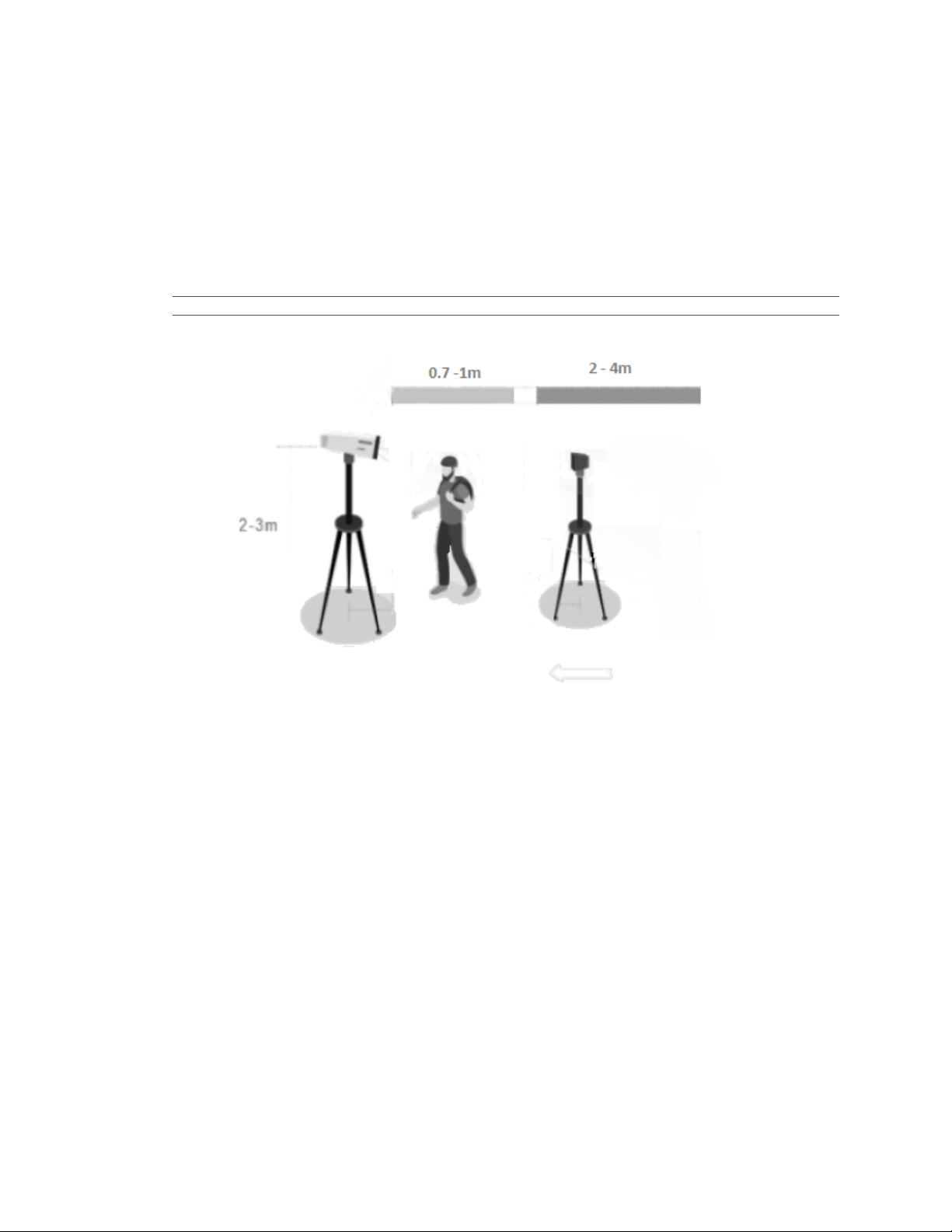
Figure 14 Single face usage setup distance recommendations
8200-1953-09 A0 15
Page 16
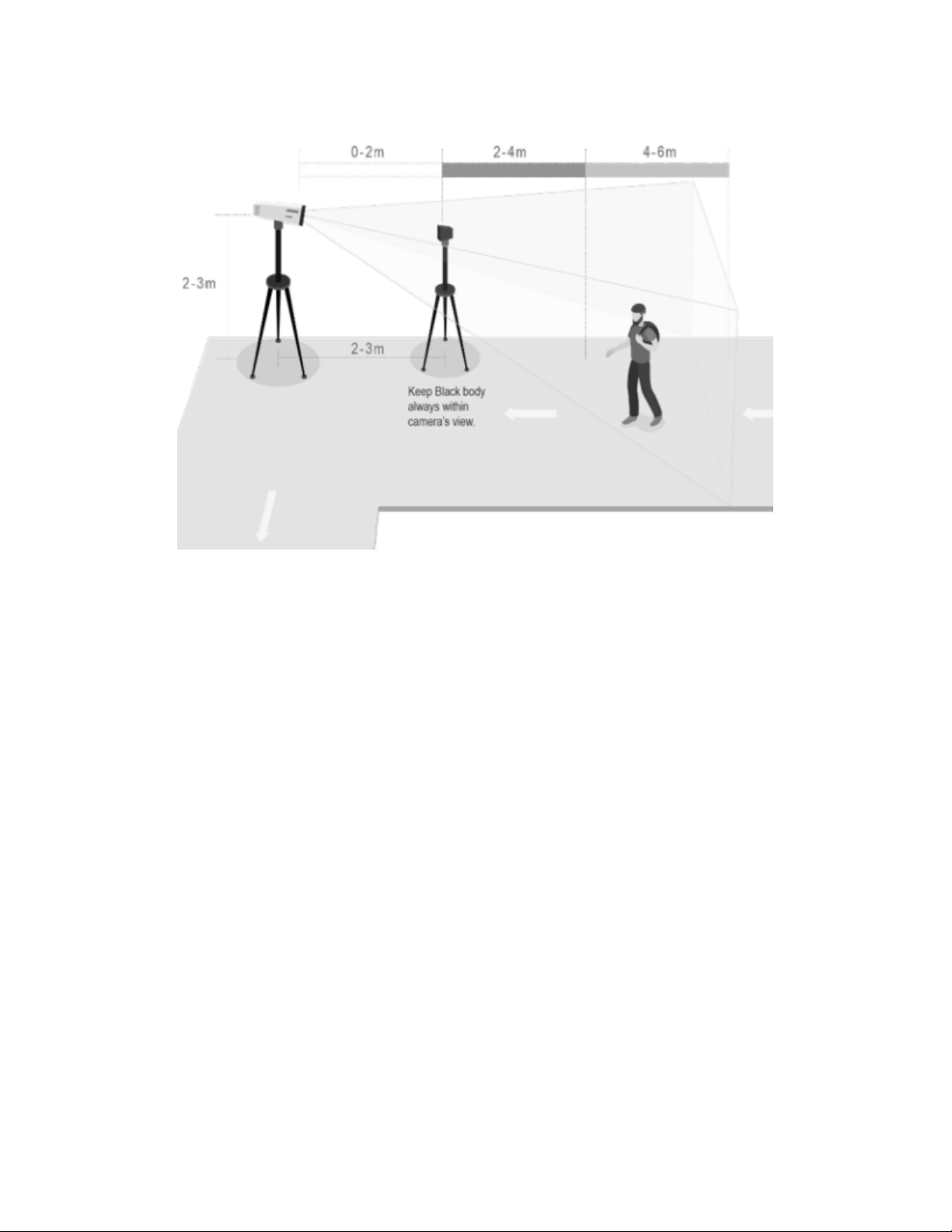
Figure 15 Multi face usage setup distance recommendations
Calibration / accuracy
• This device is specified to achieve a +/- 0.3°C accuracy when configured properly
following the installation guide and calibrated against a blackbody device. Calibration
must be done following device calibration intervals in line with the user manual
guidance in order to maintain the specified accuracy.
• The blackbody device is used to manage thermal drift compensation and is crucial in
obtaining accurate temperature assessments in line with the product accuracy
specifications.
• The solution uses the forehead region of the face using 4 sampling spots of 3x3 pixels
as the workable target plane. The total of 36 pixels is then verified to be within 0.2°C
averaged across all the pixels to ensure consistency with the highest observed
temperature being reported with the camera conducting automated calibration with the
blackbody device to manage thermal drift compensation.
Guidelines
• System architects, installers, users, and operators should refer to guidelines in ISO/TR
13154: Medical electrical equipment — Deployment, implementation and operational
guidelines for identifying febrile humans using a measurement thermograph.
• Temperature measurement with this device should not be solely or primarily relied upon
to diagnose or exclude a diagnosis of any illness, disease or other medical condition.
• The device is tested and labelled consistent with the standard IEC 80601-2-59:2017:
Medical electrical equipment – Part 2-59: Particular requirements for the basic safety
and essential performance of measurement thermographs for human febrile
temperature measurement.
16 8200-1953-09 A0
Page 17

Tyco Illustra Pro 5MP Thermal Elevated Skin Temperature Detection Camera Installation and Configuration
• Elevated skin temperature in the context of use should be confirmed with a secondary
evaluation method such as a clinical grade contact thermometer.
• The system operator must ensure the face is unobstructed by hair, eyeglasses, and
other objects because their presence will interfere with the ability of a measurement
thermograph to detect a febrile condition.
• The relative humidity in the measurement area should be maintained below 50 % and
the temperature below 24 °C for best performance. A measurement area with elevated
humidity and ambient temperature may lead to inaccurate temperature measurements
due changes in skin temperature caused by sweating.
• Public health officials, through their experience with the device in the particular
environment of use, should determine the significance of any fever or elevated
temperature based on the skin tele thermographic temperature measurement.
• This device should be used to measure only one subject's temperature at time
in accordance with IEC 80601-2-59:2017 and FDA (or other applicable
regulatory) guidelines for accuracy.
• The visible thermal patterns of this device are only intended for locating the
points from which to extract the thermal measurement.
• The product calibration interval is 14 days.
Factors to consider for the environment and installation that can impact measurement
• Thermal camera is temperature-sensitive. When it is used for temperature measuring,
in order to ensure the accuracy, the recommended ambient temperature for operation is
0~35°C and the infrared light should be turned off during the temperature measurement.
• Thermal camera should always be used together with blackbody both for increased
accuracy and to comply with IEC standards for measurement thermographs for human
febrile temperature measurement.
• Thermal camera should be used in a stable indoor environment without wind. Please
make sure the monitoring field is far away from any objects that could produce airflow,
high temperature, reflection.
• Don’t install the thermal camera opposite to a door, air conditioner or any place in or
near infrared sources such as sunlight.
• For monitoring, the best temperature measurement distance is 2~4m, recommended
distance should be 2~6m to achieve specified accuracy.
• Set up a one-way temperature measuring zone and make sure the camera can clearly
see the human face.
• After turning on, the thermal camera needs to wait 20~30 minutes to be steady.
• It is recommended to use DC 12V power supply to reduce power consumption.
• The blackbody used with the camera shall be installed 2 or 3 meters away from the
camera and opposite to the camera. It cannot be blocked. During operation, do not
move the camera and blackbody and make sure the blackbody is in a fixed and proper
place in the camera image for calibration and thermal drift compensation.
• The thermal camera and the blackbody device should be at a height of 2-3m and
parallel to the faces being screened for temperature.
8200-1953-09 A0 17
Page 18

• If the camera and/or blackbody are relocated then the customer/user/installer needs to
evaluate the new location and ensure it meets the criteria specified in this user manual,
such as guidelines, factors to consider, warnings, configuration and calibration steps,
environmental, power, air flow, and lighting parameters.
• For monitoring, the best temperature measurement distance is: Single Face Usage
recommended distance should be 0.7~1m to achieve specified accuracy, with subject
requiring to pause for about 1 second to allow for reading. Multi Face Usage
recommended distance should be 2~6m to achieve specified accuracy.
Warnings
• If the product does not work properly, please contact your dealer or the nearest service
centre. Never attempt to disassemble the camera yourself.
• Do not allow water or liquid intrusion into the camera.
• Installation and service should be performed only by qualified and experienced
technicians and comply with all local codes and rules to maintain your warranty.
• When the product is mounted on a wall ensure that the device is firmly fixed.
• Do not use the camera beyond the specified voltage range.
• Do not drop the camera or subject it to physical shock.
• Avoid touching the camera lens.
• If cleaning is necessary, please use a clean dry cloth and wipe the camera gently.
• If the device will not be used for a long time then cover the lens to protect it from dirt.
• Do not aim the camera at the sun or extra bright light sources.
• Do not place the camera in extremely hot, cold (the operating temperature shall be 0˚C~35˚C), dusty or damp locations, and do not expose it to high electromagnetic
radiation.
• To avoid heat accumulation, good ventilation is required within the operating
environment.
• Thermal imaging can detect individuals with elevated skin temperatures. However, it
cannot detect or diagnose a fever or other medical conditions. The Illustra elevated skin
temperature measurement solution does not cause and cannot eliminate or prevent
occurrences of the events that it is intended to detect or avert.
• This product requires professional installation by a service technician with the
appropriate training and experience necessary to ensure proper installation and
configuration for the applicable operating environment and usage case to ensure the
safe and accurate operation of the product.
• Product labeling is in line with the ISO/TR 13154 standard.
• Faces should be unobstructed by hair, eyeglasses, and other objects because their
presence will interfere with the ability of a thermograph detection to detect a febrile
condition. The face should be in the center of the camera view and fill approximately
50% of the thermal sensor view to achieve a 240x180 pixel resolution of the face.
• A secondary measurement with a clinical thermometer for any elevated skin
temperature alert will required to confirm a febrile condition.
• Relative humidity in the area of measurement should be maintained below 50% and the
temperature below 24°C to achieve the documented accuracy. Sweating can impact
the accuracy of temperature measurement.
18 8200-1953-09 A0
Page 19

Tyco Illustra Pro 5MP Thermal Elevated Skin Temperature Detection Camera Installation and Configuration
• Infrared sources such as sunlight, nearby electrical sources and lighting, should be
minimized to avoid impact on the accuracy of temperature reading.
• Airflow should be minimized in the area of the equipment to avoid impact on the
accuracy of temperature detection.
• The target of the body surface temperature detection will be the forehead region of the
face. 4 points of 9 pixels each. Three points factored on the center of the forehead
region, then one point left and one point right with fourth point below the center point.
8200-1953-09 A0 19
Page 20
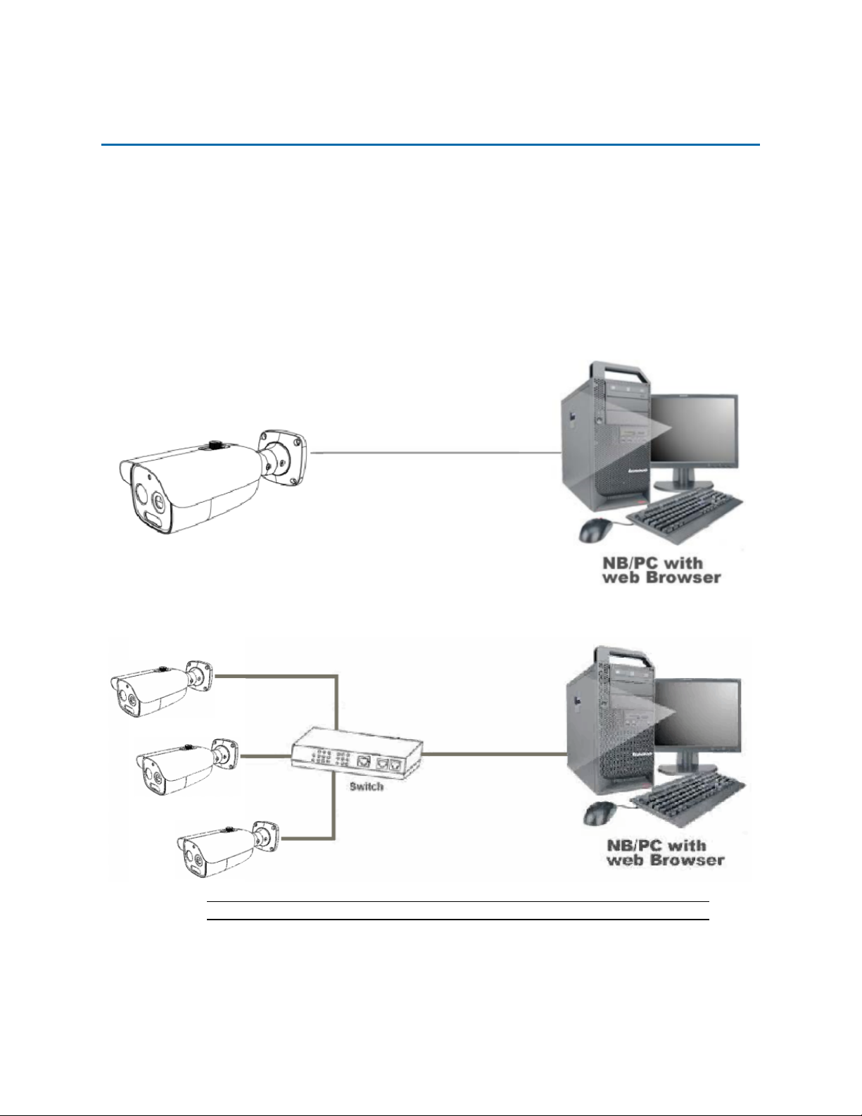
Network Topology
The Tyco Illustra Pro 5MP Thermal Elevated Skin Temperature Detection Camera delivers video
images and audio in real-time using the internet and intranet. It is equipped with an Ethernet RJ-45
network interface.
The following images illustrate the network topologies of the camera.
Tyco Illustra Pro 5MP Thermal Elevated Skin Temperature Detection Camera
Topology
Figure 16 Thermal camera Network Topology Type I
Figure 17 Thermal cameras Network Topology Type II
Note:Please check your server specification for camera connection limits.
20 8200-1953-09 A0
Page 21
Network Connection
Default IP Address
Since this is a network-based unit, an IP address must be assigned at the very first bootup. The
default IP address of the unit is 192.168.1.168 and sub mask is 255.255.255.0.
However, if you have a DHCP server in your network, the unit obtains an IP address automatically
from the DHCP server so that you do not need to change the IP address of the camera.
Note:If you assign the camera a Static IP address prior to DHCP being enabled, the camera first
reboots for approximately 30 seconds and then remains accessible at its Static IP until it connects to
a DHCP server.
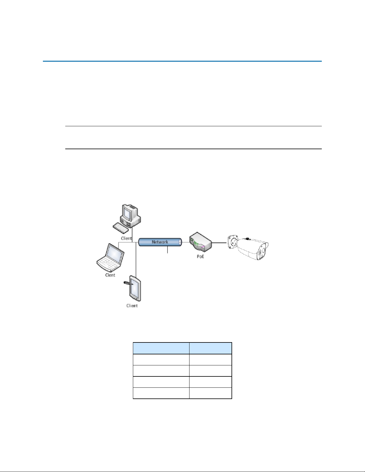
• Connect to a PC directly: Directly connect the camera to a PC using a standard Ethernet
cable. This requires POE switch or injector.
• Connecting a camera to a Local Area Network (LAN): To add the camera to an existing
LAN, connect the camera to the POE hub or switch on your network.
Figure 18 Network connection diagram
Default camera settings
The following table describes the default camera settings.
Network Settings Defaults
DHCP Enabled
Static IP Address 192.168.1.168
Default Username admin
Default Password admin
21 8200-1953-09 A0
Page 22

Tyco Illustra Pro 5MP Thermal Elevated Skin Temperature Detection Camera Installation and Configuration
Procedure 5 Connecting from a computer
Step Action
1 Ensure the camera and your computer are in the same subnet.
2 Check if the network is available between the unit and the computer by pinging the default IP
address.
a Start a command prompt.
b Type “Ping 192.168.1.168”. If the message “Reply from…” appears, it means the con-
nection is available.
3 Start Internet Explorer and enter IP address: 192.168.1.168. A login window appears. In the
window, enter the default user name: admin and password: admin to log in.
- End -
DHCP
On initial camera startup, and after a hardware factory reset, Dynamic Host Configuration Protocol
(DHCP) is enabled by default and remains enabled until the camera receives either a DHCP address
or is assigned a Static IP address.
Procedure 6 Configure the IPv4 settings
Step Action
1 Select Network on the Web User Interface banner to view the IPv4 tab.
2 Select the Obtain an IP address automatically option to automatically enable DHCP and
disable manual settings.
Or
Select the Use the following IP address option to manually enter the settings.
a Enter the IPv4 Address in the IPv4 Address text box in the form xxx.xxx.xxx.xxx. The
default setting is ‘192.168.1.168’
b Select the Test button to ensure that the IP address is correct.
c Enter the Subnet Mask in the Subnet Mask text box xxx.xxx.xxx.xxx. The default set-
ting is ‘255.255.255.0’
d Enter the Gateway IP address in Gateway text box xxx.xxx.xxx.xxx.
e Enter the Preferred DNS Server IP address in the Preferred DNS Server text box.
f Enter the Alternate DNS Server IP address in the AlternateDNS Server text box.
3 Select the Save button to save the settings.
- End -
Procedure 7 Connecting to the camera using the static IP address
Step Action
1 The camera attempts to obtain an IP Address from the DHCP Server. When no DHCP
Server is available the camera is assigned a Static IP address of 192.168.1.168.
8200-1953-09 A0 22
Page 23

2 Open Microsoft Internet Explorer and enter the URL of the camera as 192.168.1.168. The
camera sign in page displays.
Note:The computer you use to configure the camera must have an IP address on the same subnet.
- End -
Procedure 8 Logging on to the camera web user interface
Step Action
1 When you select the camera, the sign in page displays. Select your preferred language from
the drop-down menu.
2 Enter the username in the Username text box. The default username is admin.
3 Enter the password in the Password text box. The default password is admin.
4 Select Log in.
5 The Live view page is visible. This displays the current view of the camera.
- End -
23 8200-1953-09 A0
Page 24
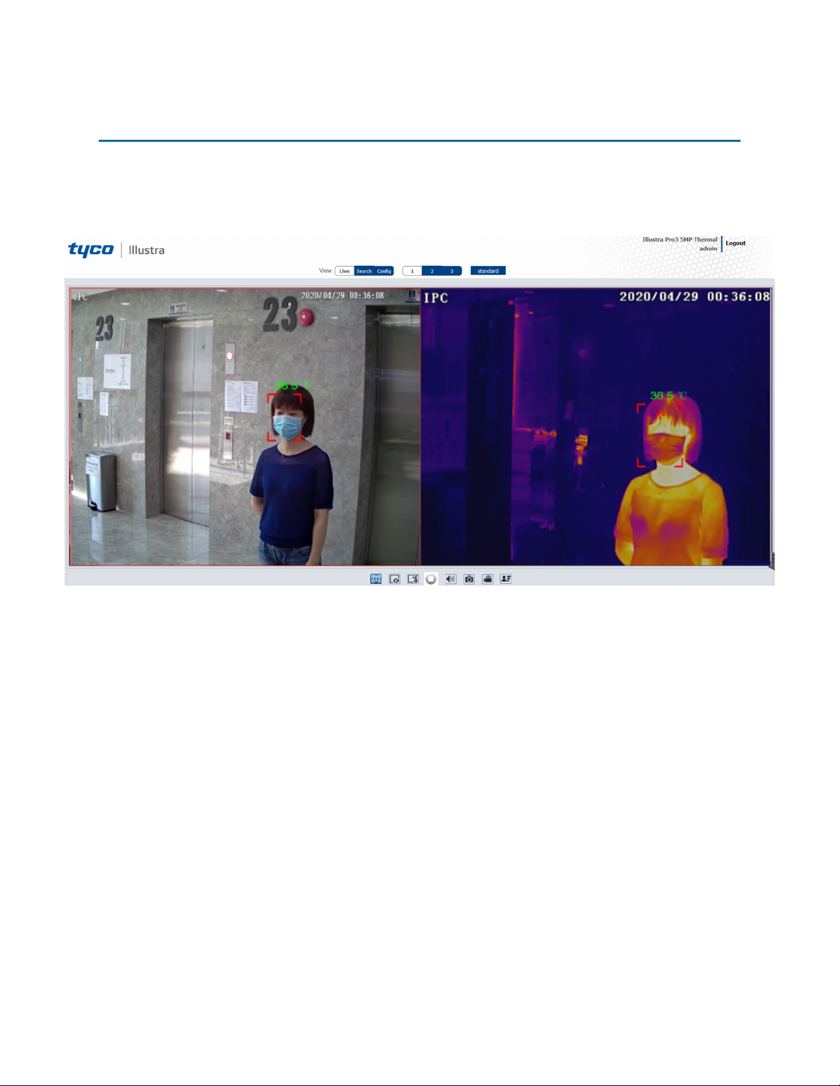
Live View
After configuring temperature measurement and face detection, the temperature and face detection
results can be viewed on the screen.
Figure 19 Live View menu
24 8200-1953-09 A0
Page 25
Tyco Illustra Pro 5MP Thermal Elevated Skin Temperature Detection Camera Installation and Configuration
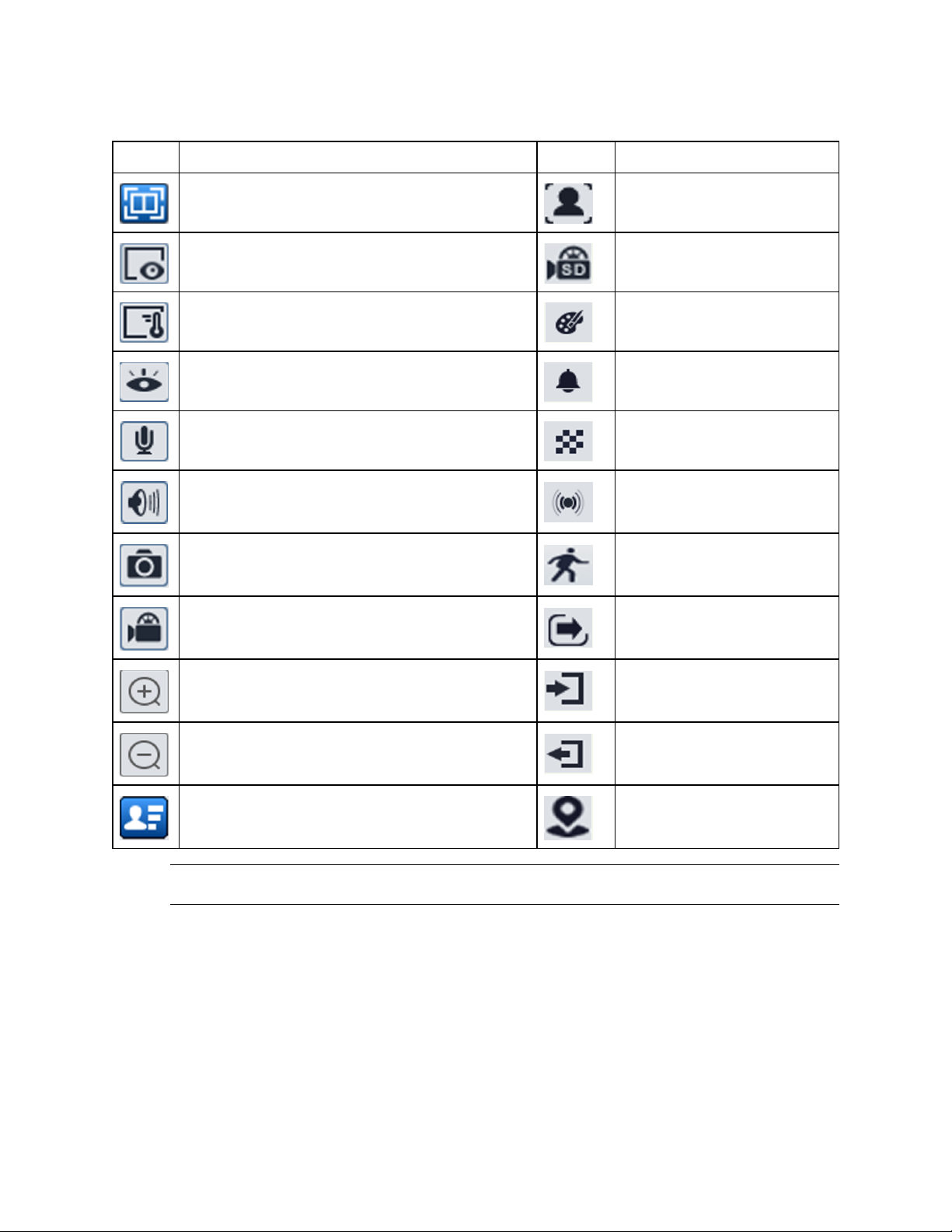
Table 20 Live view menu icons and descriptions
Icon Description Icon Description
Visible light image and thermal image display Face detection indicator
Visible light image display SD card recording indicator
Thermal image display Color abnormal indicator
Start / stop live view Abnormal clarity indicator
Start / stop two-way audio Scene change indicator
Enable/disable audio Sensor alarm indicator
Snapshot Motion alarm indicator
Start / stop local recording Line crossing indicator
Zoom in Region entrance indicator
Zoom out Region exiting indicator
Face Detection Intrusion indicator
Note:The smart alarm indicators flash only when the camera supports those functions and the
corresponding events are enabled.
8200-1953-09 A0 25
Page 26
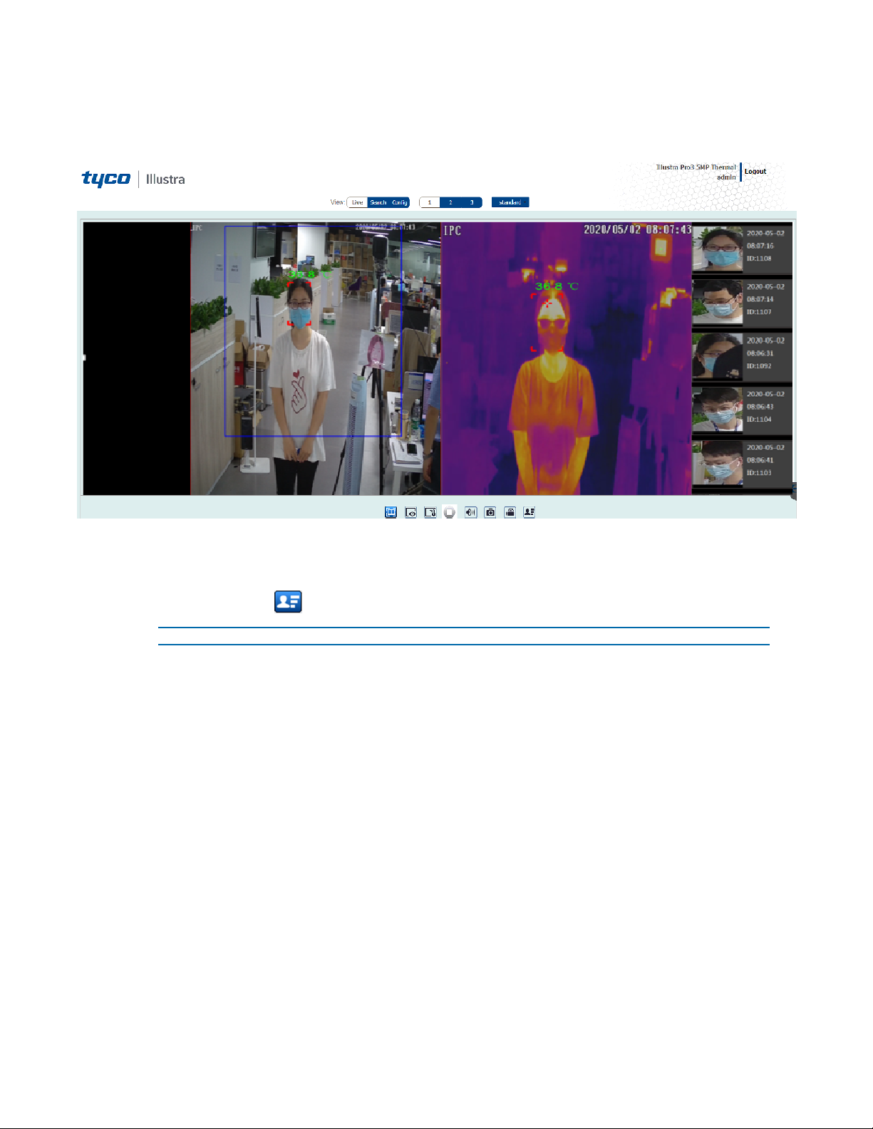
Face Detection View
Figure 21 Face Detection view menu
Procedure 9 Viewing captured face detection pictures
1 Select the Live button.
2 Select the icon to view a list of all captured faces.
- End -
26 8200-1953-09 A0
Page 27
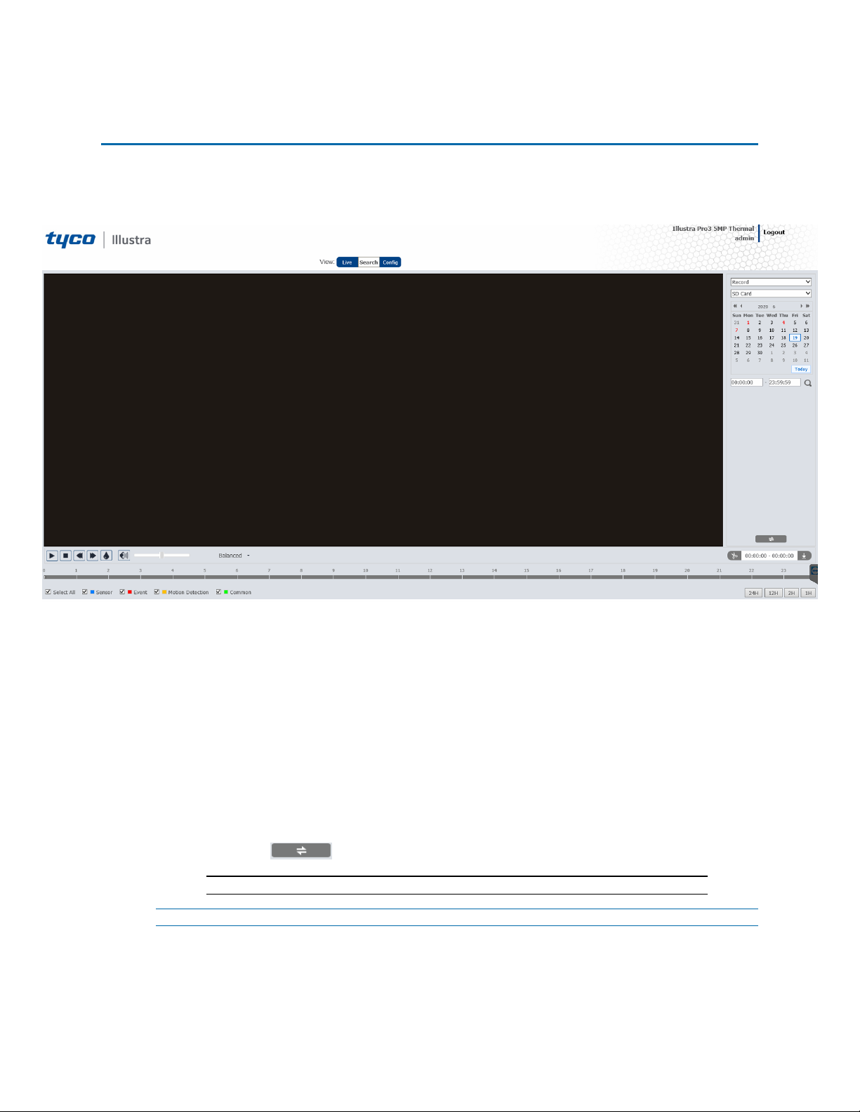
Search
You can search for images and recording clips within a specific time and date
Figure 22 Search menu
Procedure 10 Searching for images locally
1 Select the Search button.
2 Select the Record drop-down menu and select Picture.
3 Select the SD Card drop-down menu and select Local.
4 Select a date in the calendar.
5 Select the first text box under the calendar and enter a start time.
6 Select the second text box under the calendar and enter a finish time.
7 Select the search icon to view a list of the images.
8 Double click a file name in the list to view the captured images.
9 Select the icon to return to the previous interface.
Note:See Table 18 for a list of options available once you have located an image.
- End -
Procedure 11 Searching for images on the SD card
1 Select the Search button.
27 8200-1953-09 A0
Page 28
Tyco Illustra Pro 5MP Thermal Elevated Skin Temperature Detection Camera Installation and Configuration
2 Select the Record drop-down menu and select Picture.
3 Select the SD Card drop-down menu and select SD Card.
4 Select a date in the calendar.
5 Select the first text box under the calendar and enter a start time.
6 Select the second text box under the calendar and enter a finish time.
7 Select the search icon to view a list of the recordings.
8 Double click a file name in the list to view the captured images.
9 Select the icon to return to the previous interface.
Note:See Table 18 for a list of options available once you have located an image.
- End -
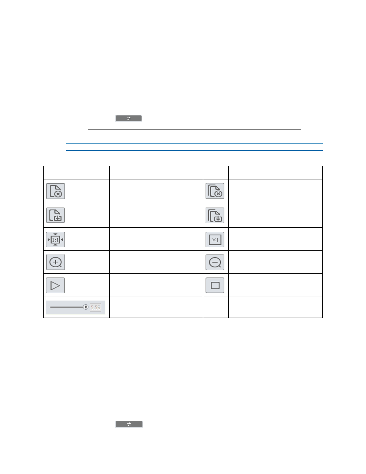
Table 23 Options available after you locate an image
Icon Description Icon Description
Close: Select an image and click
this button to close the image.
Save: Click this button to select the
path for saving the image on the
PC.
Fit size: Click to fit the image on the
screen.
Zoom in: Click this button to digitally zoom in.
Slide show play: Click this button to
start the slide show mode.
Play speed: Play speed of the slide
show.
Procedure 12 Searching for recordings locally
1 Select the Search button.
2 Select the Record drop-down menu and select Record.
Close all: Click this button to close
all images.
Save all: Click this button to select
the path for saving all pictures on
the PC.
Actual size: Click this button to display the actual size of the image.
Zoom out: Click this button to digitally zoom out.
Stop: Click this button to stop the
slide show.
3 Select the SD Card drop-down menu and select Local.
4 Select a date in the calendar.
5 Select the first text box under the calendar and enter a start time.
6 Select the second text box under the calendar and enter a finish time.
7 Select the search icon to view a list of recordings.
8 Double click a file name to play the recording.
9 Select the icon to return to the previous interface.
8200-1953-09 A0 28
Page 29
Note:See Table 19 for a list of options available once you have located a recording.
- End -
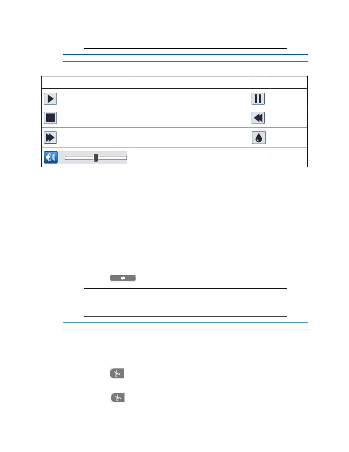
Table 24 Options available after you locate a recording
Icon Description Icon Description
Play button. After pausing the video, click this
button to continue playing.
Stop button Speed down
Speed up
Enable / disable audio; drag the slider to adjust
the volume after enabling audio.
Procedure 13 Searching for recordings on the SD card
1 Select the Search button.
2 Select the Record drop-down menu and select Record.
3 Select the Local drop-down menu and select SD Card.
4 Select a date in the calendar.
5 Select the first text box under the calendar and enter a start time.
6 Select the second text box under the calendar and enter a finish time.
7 Select the Alarm check box at the bottom of the interface.
8 Select mix stream (video and audio stream) or video stream as needed.
Pause button
Watermark
display
9 Double click a file name in the list to view the captured recordings.
10 Select the icon to return to the previous interface.
Note:See Table 19 for a list of options available once you have located a recording.
Note:The time table can be shown in 24H/12H/2H/1H format by clicking the
corresponding buttons.
- End -
Procedure 14 Downloading a video clip
1 Search for the recording as per Procedure 14 or Procedure 15.
2 Select the start time by clicking on the overall recording time line.
3 Select the icon to set the start time.
4 Select the end time by clicking on the overall recording time line.
5 Select the icon to to set the end time.
29 8200-1953-09 A0
Page 30

Tyco Illustra Pro 5MP Thermal Elevated Skin Temperature Detection Camera Installation and Configuration
6 Select the icon to download the video file in the PC.
• Select the Set up button to set the storage directory of the video files.
• Select the Open button to play the video.
• Select the Clear List button to clear the downloading list.
• Select the Close button to close the downloading window.
- End -
8200-1953-09 A0 30
Page 31

Configuration
The following sections explain how you can configure the Tyco Illustra Pro 5MP Thermal Elevated
Skin Temperature Detection Camera using the Web User Interface.
Accessing the Tyco Illustra Pro 5MP Thermal Elevated Skin Temperature
Detection Camera Web User Interface
Use the following procedure to access the camera Web User Interface. Use Internet Explorer 11 web
browser.
Procedure 15 Logging in to the Camera
Step Action
1 Refer to Network Connection on page 21 for details on how to connect the camera to your
network or computer.
2 When you select the camera, the sign in page displays.
3 Select your preferred language from the drop-down menu. The default language is English.
4 Enter the default username and password when prompted - Username: admin, Password:
admin.
5 Click Log in. The camera Web User Interface displays. The first time that you log into the
camera you are prompted to change the password.
6 Once the above steps are complete, the Live view page is visible. This displays the current
view of the camera.
- End -
31 8200-1953-09 A0
Page 32

Tyco Illustra Pro 5MP Thermal Elevated Skin Temperature Detection Camera Installation and Configuration
Changing the Camera Web User Interface Language
Use the following procedure to change the language used in the camera Web User Interface.
Procedure 16 Change the Camera Web User Interface Language
Step Action
1 Open the camera sign in page. If you are already logged in to the Web User Interface, select
Log Off to display the sign in page.
2 Select your preferred language from the drop-down menu:
• English
• Chinese (Simplified)
• Chinese (Traditional)
• Japanese
• Korean
The default language is English.
3 Enter the Username.
4 Enter the Password.
5 Select Log in.
The camera web User Interface displays in the selected language.
- End -
8200-1953-09 A0 32
Page 33

Image
In this section you can configure the display settings, video and audio, on-screen display, video
mask and regions of interest.
Figure 25 Image settings menu page
Display Settings
In this section you can adjust the camera parameter settings and schedule image parameters
settings.
Procedure 17 Adjusting the camera parameters
1 Select Image on the Web User Interface banner to view the Camera Parameters tab.
2 Select the Config File drop-down menu and select one of the following:
• Common
• Day
• Night
3 Adjust the slide-bar to select a value for the options in the list below:
• Brightness: Set the brightness level of the camera’s image.
• Contrast: Set the color difference between the brightest and darkest
parts.
• Hue: Set the total color degree of the image.
33 8200-1953-09 A0
Page 34

Tyco Illustra Pro 5MP Thermal Elevated Skin Temperature Detection Camera Installation and Configuration
• Saturation: Set the degree of color purity. The purer the color, the
brighter the image is.
• Sharpness: Select the Sharpness check box and then set the res-
olution level of the image plane and the sharpness level of the image
edge.
• Noise Reduction: Select the Noise Reduction check box and set
the noise reduction value. Decrease the noise and make the image
more thorough. Increasing the value will make the noise reduction
effect better but it will reduce the image resolution.
• Defog: Select the Defog check box and set the defog value. Activ-
ating this function and setting an appropriate value as needed in foggy,
dusty, smoggy or rainy environment to get clear images.
4 Select an option from the drop-down menu for each of the following:
• Backlight Compensation (BLC):
Off: disables the backlight compensation function. It is the default mode.
HWDR: WDR can adjust the camera to provide a better image when there are both
very bright and very dark areas simultaneously in the field of the view by lowering
the brightness of the bright area and increasing the brightness of the dark area.
Recording will be stopped for a few seconds while the mode is changing from nonWDR to WDR mode.
HLC: lowers the brightness of the entire image by suppressing the brightness of the
image’s bright area and reducing the size of the halo area.
BLC: If enabled, the auto exposure will activate according to the scene so that the
object of the image in the darkest area will be seen clearly.
• Antiflicker:
Off: disables the anti-flicker function. This is used mostly in outdoor installations.
50Hz: reduces flicker in 50Hz lighting conditions.
60Hz: reduces flicker in 60Hz lighting conditions.
• Smart IR: Choose “ON” or “OFF”. This function can effectively avoid
image overexposure and underexposure by controlling the brightness
of the IR lights according to the actual conditions to make the image
more realistic. Please enable it as needed.
• White Balance: Adjust the color temperature according to the envir-
onment automatically.
• Frequency: 50Hz and 60Hz can be optional.
• Day/Night Mode: Choose “Auto”, “Day”, “Night” or “Timing”.
• Infra-red Mode: ''On'' or ''Off''.
• Gain Mode: Choose “Auto” or “Manual”. If “Auto” is selected, the gain
value will be automatically adjusted according to the actual situation. If
“Manual” is selected, the gain value shall be set manually. The higher
the value is, the brighter the image is.
• Gain Limit: Adjust the slide-bar to increase or decrease the value.
Note:To restore the settings to their default value then select the Default button.
8200-1953-09 A0 34
Page 35

Note:Select Cancel to undo any changes.
- End -
Procedure 18 Scheduling when certain camera parameters should be used
1 Select Image on the Web User Interface banner to view the Camera Parameters tabs.
2 Select the Schedule tab to view the schedule menu.
3 Select the Schedule drop-down menu and one of the following:
• Full Time for common, day, night mode
• Timing to enter a time.
Note:When Timing is selected then you must click and drag the Timing Range
slide-bar to enter the time.
4 Select the Config File drop-down menu and select one of the following:
• Common
• Day
• Night
• Auto
5 Select the Save button to save the settings.
- End -
Video / Audio
In this section you can set the video and audio settings.
Procedure 19 Configuring the video settings
Four video streams can be adjusted at the same time.
1 Select Image on the Web User Interface banner to view the Video / Audio option in the
menu list.
2 Select Video / Audio to view the Video tab to view the video menu.
3 Select the Resolution drop-down menu and select the size of the image.
4 Select the Frame Rate text box to enter a value for the frame rate.
5 Select the Bitrate Type drop-down menu and select one of the following:
• CBR - no matter how much change is seen in the video scene, the compression bitrate will be kept constant.
• VBR - the compression bitrate will be adjusted according to scene
changes. For example, for scenes that do not have much movement,
the bitrate will be kept at a lower value. This can help optimize the network bandwidth usage.
6 Select the Bitrate(Kbps) drop-down menu and select an option.
Note:This option is only available when CBR is selected in step 5.
35 8200-1953-09 A0
Page 36

Tyco Illustra Pro 5MP Thermal Elevated Skin Temperature Detection Camera Installation and Configuration
7 Select the Video Quality drop-down menu and select an option. The higher the image
quality then more bitrate will be required.
Note:This option is only available when VBR is selected in step 5.
8 Select the I Frame Interval text box to enter a value for the I frame.
Note:I frame determines how many frames are allowed between a “group of
pictures”. When a new scene begins in a video, until that scene ends, the entire
group of frames (or pictures) can be considered as a group of pictures. If there is not
much movement in the scene, setting the value higher than the frame rate is fine,
potentially resulting in less bandwidth usage. However, if the value is set too high,
and there is a high frequency of movement in the video, there is a risk of frame
skipping.
9 Select the Video Compression drop-down menu to select the video compression type.
Note:H264, H265, and MJPEG are optional.
Note:If H.265 is chosen, make sure the client system is able to decode H.265
10 Select the Profile drop-down menu to select the profile type. For H.264. Baseline, main and
high profiles are selectable.
11 Select the Send Snapshot drop-down menu to select the number of snapshots to generate
for an event.
12 Select the Video encode slice split check box to ensure a smooth image even when using
the low-performance computer.
13 Select the Watermark check box to enable this option when playing the local recorded video
in the search interface.
14 Select the Watermark content text box and enter a description.
15 Select the Save button to save the settings.
- End -
Procedure 20 Configuring the audio settings
1 Select Image on the Web User Interface banner to view the Video / Audio option in the
menu list.
2 Select the Video / Audio option and then the Audio tab to view the audio menu.
3 Select the Enable check box to enable audio.
4 Select the Audio Encoding drop-down menu and select one the following:
• G711A
• G711U
5 Select the Audio Type drop-down menu and select the following:
• LIN
6 Select the Speaker drop-down menu and select the following:
• Warning
8200-1953-09 A0 36
Page 37

When “Talkback” is selected, the external audio output device will be used to output sound
for two-way talk. When “Warning” is selected, the external audio output device will be used
to output the pre-defined audio alarm.
7 Select the Speaker drop-down menu and select the following:
• Warning
When “Talkback” is selected, the built-in speaker will be used to output sound for two-way
talk. When “Warning” is selected, the built-in speaker will be used to output the pre-defined
audio alarm.
8 Select the Save button to save the settings.
- End -
On Screen Display (OSD)
In this section you can select the date format, enter a device name, add OSD content and picture
overlap here. After enabling the corresponding display and entering the content you can drag them to
change their position.
Procedure 21 Settings up on screen display
You can add the date, time and device name to the on screen display.
1 Select Image on the Web User Interface banner to view the OSD option in the menu list.
2 Select the OSD option to view the OSD menu.
3 Select the Date Format drop-down menu and select a date format.
4 Select the Show Timestamp check box to view the date on screen.
5 Select the Device Name text box and enter the name of the device.
6 Select the Show Device Name check box to view the device name on screen.
Note:You can move the on screen display around the screen.Click and hold the on
screen display to move it around the screen.
7 Select the Save button to save the settings.
- End -
Procedure 22 Uploading the on screen display settings
1 Select Image on the Web User Interface banner to view the OSD option in the menu list.
2 Select the OSD option to view the OSD menu.
3 Select the OSD Content 1 check box drop-down menu and select Picture Overlay from
the drop down menu.
4 Select Browse to select the overlap picture and then select Upload to upload the overlap
picture.
Note:The pixel of the image shall not exceed 200*200, or it cannot be uploaded.
5 Select the Save button to save the settings.
- End -
37 8200-1953-09 A0
Page 38

Tyco Illustra Pro 5MP Thermal Elevated Skin Temperature Detection Camera Installation and Configuration
Video Mask
A maximum of four video masks can be setup.
Procedure 23 Adding a video mask
1 Select Image on the Web User Interface banner to view the View Mask option in the menu
list.
2 Select the Video Mask option to view the Video Mask menu.
3 Select the Enable check box to enable a video mask.
4 Select the Draw Area button and then drag the mouse over the video and draw the video
mask.
Note:Select the Clear button to remove the video mask.
5 Select the Save button to save the settings.
- End -
Region of Interest (ROI) Configuration
An area in the image can be set as a region of interest. This area will have a higher bitrate than the
rest of the image, resulting in better image quality for the identified area.
Procedure 24 Adding a region of interest
1 Select Image on the Web User Interface banner to view the ROI Config option in the menu
list.
2 Select the ROI Config option to view the ROI menu.
3 Select the Enable check box to enable a region of interest
4 Select the Draw Area button and then drag the mouse over the video and draw the region of
interest.
Note:Select the Clear button to remove the video mask.
5 Adjust the Level slide-bar to set the region of interst level on screen.
6 Select the Save button to save the settings.
- End -
8200-1953-09 A0 38
Page 39

Temperature
In this section you can set the temperature and an alarm type and schedule when the temperature
measurement should be performed.
Figure 26 Temperature settings menu page
Temperature measurement
In this section you can set the temperature and an alarm type.
Procedure 25 Configuring temperature measurements
1 Select Temperature on the Web User Interface banner to view the Detection Config tab.
2 Select the Enable check box to enable temperature measurement.
3 Select the Temperature Switch drop-down menu and select one of the following:
• Celsius
• Fahrenheit
4 Select the High Temperature Alarm check box and enter a value in the text box
5 Select the Low Temperature Alarm check box and enter a value in the text box.
39 8200-1953-09 A0
Page 40

Tyco Illustra Pro 5MP Thermal Elevated Skin Temperature Detection Camera Installation and Configuration
Note:When the body temperature measured is higher or lower than the set value, it
will trigger alarms.
6 Select the Alarm Holding Time drop-down menu and select an option.
7 Select the following check boxes to trigger that alarm:
• Alarm Out: If enabled, the alarm output device will be triggered when
detecting abnormal temperature.
• Trigger Audio Alarm: If enabled, the warning voice will be triggered
when the temperature exceeds the set value. (Please set the warning
voice first. See Audio Alarm for details)
• Trigger Light Alarm: If enabled, the light of the camera will flash
when the temperature exceeds the set value. (Please set the light flashing time and frequency first. See Light Alarm for details)
• Trigger Snap: If enabled, the system will capture images on detecting
abnormal temperature alarm and save the images on an SD card.
• Trigger SD Recording: If selected, video will be recorded on an SD
card on detecting abnormal temperature alarm.
• Trigger Email: If Trigger Email and Attach Picture are checked (email
address must be set first in the Email configuration interface), the captured pictures and triggered event will be sent into those addresses.
• Trigger FTP: If Trigger FTP is checked, the captured pictures will be
sent into FTP server address. Please refer to FTP configuration
chapter for more details.
8 Select the Save button to save the settings.
- End -
8200-1953-09 A0 40
Page 41

Temperature measurement schedule
In this section you can schedule when the temperature measurement should be performed.
Figure 27 Temperature measurement schedule menu page
Procedure 26 Adding a weekly temperature schedule
You can set the alarm time from Monday to Sunday for a single week. Each day is divided in one hour
increments. Blue in Figure 22 means scheduled. No colour means that its unscheduled.
1 Select Temperature on the Web User Interface banner to view the Detection Config tab.
2 Select the Schedule tab to view the schedule menu.
3 Select Add for any day to schedule the temperature measurement and then click and drag
the mouse over the timeline to set the time.
Or
Select Manual Input for any day to select a specific start and end time. This adds more
granularities (minutes).
Note:Select Erase for any day to delete the schedule in step 3 and then click and
drag the mouse over the timeline to erase the time.
4 Select the Save button to save the settings.
- End -
Procedure 27 Adding a daily temperature schedule
You can set the alarm time for a special day, such as a holiday.
1 Select Temperature on the Web User Interface banner to view the Detection Config tab.
41 8200-1953-09 A0
Page 42

Tyco Illustra Pro 5MP Thermal Elevated Skin Temperature Detection Camera Installation and Configuration
2 Select the Schedule tab to view the schedule menu.
3 Select the Date text box and enter a date.
4 Select Add for any day to schedule the temperature measurement and then click and drag
the mouse over the timeline to set the time.
Or
Select Manual Input for any day to select a specific start and end time. This adds more
granularities (minutes).
Note:Select Erase for any day to delete the schedule in step 3 and then click and
drag the mouse over the timeline to erase the time.
5 Select the Save button to save the settings.
- End -
8200-1953-09 A0 42
Page 43

Temperature Calibration
In this section you can configure a temperature calibration with or without the blackbody.
Figure 28 Temperature Calibration menu page
Procedure 28 Configuring a temperature calibration with the blackbody
1 Select Temperature on the Web User Interface banner and then select Temperature Cal-
ibration from the menu list.
2 Select the Usage drop-down menu and select Single Face or Multiple Face.
• Single Face Usage = 1 Face at time between .7 and 1 Meter from the
camera at a max rate of 10 to 15 people per minute or one every 4
seconds. (IEC compliant).
• Multi Face Usage = Up to 20 faces at a time between 2 and 6 meters
at a max rate of 200 people per minute or 20 people at a time. (Not IEC
compliant).
3 Select the Ambient Temperature text box and enter the ambient temperature value.
The recommended ambient temperature should be 10~35°C (airless).
4 Select the Ambient Humidity text box and enter the ambient humidity value.
The recommended ambient humidity should be less than 50%.
5 Select the Object Distance text box and enter a value for the distance between the camera
and user.
6 Select the Emissivity text box and enter a value.
For human skin, this value is normally set as 95%.
7 Select the Blackbody drop-down menu and select Open.
43 8200-1953-09 A0
Page 44

Tyco Illustra Pro 5MP Thermal Elevated Skin Temperature Detection Camera Installation and Configuration
Note:A red box is now visible in the thermal image window. See example in Figure
28. The blackbody should not be visible within this area for accuracy measurement.
If the blackbody is outside of the box then move it within the box.
Note:It is important that the blackbody is in a position where it will not be obscured
during detection.
Figure 29 'Red Box' visible in the thermal image window
8 Select the Blackbody Temperature text box and enter a value.
It is recommended that this is set to 35°C
Note:Turn on the blackbody and then press “Up” or “Down” to increase or decrease
the temperature value. It can take about 20~30 minutes for the blackbody to be
steady.
9 Select the Blackbody Mode drop-down menu and select Auto or Manual.
Note:It is recommended to select “Auto” mode and use the default settings.
Note:If “Manual” is selected, then please calibrate the temperature as follows.
Move the cursor to the blackbody image in the temperature calibration interface.
The temperature is then visible on screen. If this value is not 35°C, please select
the Temperature Correction text box and enter the value.
10 Select the Temperature Correction text box and input the value offset from the overlay
blackbody temperature.
Example: If The Blackbody is set to 35.0 and the camera is reading 34.9 – then the offset
would be 0.1.
Note:Configure and save the calibration settings from this procedure before
establishing this offset.
11 Select the Calibarate button and then select Save to save the settings.
8200-1953-09 A0 44
Page 45

Note:The Blackbody target icon will not update the read temperature value until the
page is refreshed or the target icon is repositioned within the Blackbody.
Note:It may take up to 10 minutes to make the temperature module of the camera
stable. Therefore, please measure the body temperature after 10 minutes.
Note:The Blackbody does not support IP40. If the blackbody is used with the
camera, it shall be installed 2 or 3 meters away from the camera. It cannot be
blocked. During operation, do not move the camera and blackbody and make sure
the blackbody is in a fixed and correct position in the camera image.
- End -
Display Settings
In this section you can select a colorization option.
Procedure 29 Selecting a temperature display setting
1 Select Temperature on the Web User Interface banner and then select Display Settings
from the menu list.
2 Select the Colorization drop down menu and select one of the following:
• Iron oxide red
• Rainbox
• White hot
• Black hot
• Green jade
3 Select the Save button to save the settings.
- End -
45 8200-1953-09 A0
Page 46

Alarm and Event
In this section you can configure motion detection, an SD card, alarm in and out, the alarm server,
audio alarm, light alarm, set the camera to detect changes in the surveillance environment affected
by the external factors, the sensitivity the system responds to the amplitude of the scene change,
trigger alarms and set areas of interest.
Figure 30 Alarm and Event settings menu page
Motion Detection
Procedure 30 Configuring a motion detection alarm
Four video streams can be adjusted at the same time.
1 Select Alarm and Event on the Web User Interface banner to view the Motion tab.
2 Select the Enable check box to activate motion based alarms.
Note:If unchecked, the camera will not send out any signals to trigger motion-based
recording to the NVR or CMS, even if there is motion in the video.
3 Select the Alarm Holding Time drop-down menu and select an option.
4 Select the following check boxes to enable that alarm:
• Alarm Out:If selected, this would trigger an external relay output that
is connected to the camera on detecting a motion based alarm.
• Trigger Audio Alarm: If selected, the warning voice will be uttered on
detecting a motion based alarm. (Please set the warning voice first.
See Audio Alarm for details).
46 8200-1953-09 A0
Page 47

Tyco Illustra Pro 5MP Thermal Elevated Skin Temperature Detection Camera Installation and Configuration
• Trigger Snap: If selected, the system will capture images on motion
detection and save the images on an SD card.
• Trigger SD Recording: If selected, video will be recorded on an SD
card on motion detection.
• Trigger Email: If “Trigger Email” and “Attach Picture” are selected
(email address must be set first in the Email configuration interface),
the captured pictures and triggered event will be sent into those
addresses.
• Trigger FTP: If selected, the captured pictures will be sent into FTP
server address. Please refer to FTP configuration chapter for more
details.
5 Select the Save button to save the settings.
- End -
Procedure 31 Select the motion detection area and sensitivity
1 Select Alarm and Event on the Web User Interface banner to view the Motion tab.
2 Select the Area and Sensitivity tab.
3 Move the Sensitivity slide-bar to set the sensitivity. A higher sensitivity value means that
motion will be triggered more easily.
4 Select Add and then select the Draw Area button.
5 Click and drag the mouse over the screen to draw the motion detection area.
Note:Select the Clear All button and then click and drag the mouse over the
screen to erase the motion detection area.
Note:Select the Select All button to select the full drawing.
Note:Select the Invert button to invert the drawing.
6 Select the Save button to save the settings.
- End -
Procedure 32 Schedule a motion detection alarm
1 Select Alarm and Event on the Web User Interface banner to view the Motion tab.
2 Select the Schedule tab.
3 See the Schedule section in the Temperature Measurement Schedule section on page 41 for
assistance.
- End -
8200-1953-09 A0 47
Page 48

Anomaly
In this section you can take an action, such as triggering an alarm, if the SD card is full, has an error
or if the camera experiences some error such as the IP collision or cable disconnection.
Procedure 33 Enable an alarm when the SD Card is full
1 Select Alarm and Event on the Web User Interface banner and then select Anomaly.
2 Select the Enable check box.
3 Select the Alarm Holding Time drop-down menu and select a time.
4 Select one of the following check boxes to trigger the alarm:
• Alarm Out: If enabled, the alarm output device will be triggered when
detecting abnormal temperature.
• Trigger Email: If Trigger Email and Attach Picture are checked (email
address must be set first in the Email configuration interface), the captured pictures and triggered event will be sent into those addresses.
• Trigger FTP: If Trigger FTP is checked, the captured pictures will be
sent into FTP server address. Please refer to FTP configuration
chapter for more details.
5 Select the Save button to save the settings.
- End -
Procedure 34 Enable an SD Card Error alarm
1 Select Alarm and Event on the Web User Interface banner and then select Anomaly.
2 Select the SD Card Error tab.
3 Select the Enable check box.
4 Select the Alarm Holding Time drop-down menu and select a time.
5 Select one of the following check boxes to trigger the alarm:
• Alarm Out: If enabled, the alarm output device will be triggered when
detecting abnormal temperature.
• Trigger Email: If Trigger Email and Attach Picture are checked (email
address must be set first in the Email configuration interface), the captured pictures and triggered event will be sent into those addresses.
• Trigger FTP: If Trigger FTP is checked, the captured pictures will be
sent into FTP server address. Please refer to FTP configuration
chapter for more details.
6 Select the Save button to save the settings.
- End -
Procedure 35 Enable an IP Address Collision alarm
1 Select Alarm and Event on the Web User Interface banner and then select Anomaly.
2 Select the IP Address Collision tab.
3 Select the Enable check box.
48 8200-1953-09 A0
Page 49

Tyco Illustra Pro 5MP Thermal Elevated Skin Temperature Detection Camera Installation and Configuration
4 Select the Alarm Holding Time drop-down menu and select a time.
5 Select the following check box to trigger the alarm.
• Alarm Out: If enabled, the alarm output device will be triggered when
detecting abnormal temperature.
6 Select the Save button to save the settings.
- End -
Procedure 36 Enable an alarm when a cable is disconnected
1 Select Alarm and Event on the Web User Interface banner and then select Anomaly.
2 Select the Cable Disconnected tab.
3 Select the Enable check box.
4 Select the Alarm Holding Time drop-down menu and select a time.
5 Select the following check box to trigger the alarm.
• Alarm Out: If enabled, the alarm output device will be triggered when
detecting abnormal temperature.
6 Select the Save button to save the settings.
- End -
Alarm In
Procedure 37 Enable an Alarm In alarm.
1 Select Alarm and Event on the Web User Interface banner and then select Alarm In.
2 Select the Enable check box.
3 Select the Alarm Type drop-down menu and select an option.
4 Select the Alarm Holding Time drop-down menu and select an option.
5 Select the Sensor Name text box and enter a name.
6 Select the following check boxes to trigger that alarm:
• Alarm Out: If enabled, the alarm output device will be triggered when
detecting abnormal temperature.
• Trigger Audio Alarm: If enabled, the warning voice will be triggered
when the temperature exceeds the set value. (Please set the warning
voice first. See Audio Alarm for details)
• Trigger Light Alarm: If enabled, the light of the camera will flash
when the temperature exceeds the set value. (Please set the light flashing time and frequency first. See Light Alarm for details)
• Trigger SD Snap: If enabled, the system will capture images on
detecting abnormal temperature alarm and save the images on an SD
card.
• Trigger SD Recording: If selected, video will be recorded on an SD
card on detecting abnormal temperature alarm.
8200-1953-09 A0 49
Page 50

• Trigger Email: If “Trigger Email” and “Attach Picture” are checked
(email address must be set first in the Email configuration interface),
the captured pictures and triggered event will be sent into those
addresses.
• Trigger FTP: If “Trigger FTP” is checked, the captured pictures will be
sent into FTP server address. Please refer to FTP configuration
chapter for more details.
7 Select the Save button to save the settings.
- End -
Procedure 38 Schedule an alarm in alarm
1 Select Alarm and Event on the Web User Interface banner and then select Alarm In.
2 Select the Schedule tab.
3 See the Schedule section in the Temperature Measurement Schedule section on page 41 for
assistance.
- End -
Alarm Out
Procedure 39 Enable an Alarm Out alarm.
1 Select Alarm and Event on the Web User Interface banner and then select Alarm Out.
2 Select one of the following from the Alarm Out Mode drop down menu:
• Alarm Linkage: When selected , enter the Alarm Out Name, and
select the Alarm Holding Time and Alarm Type from the drop-down
menus.
• Manual Operation: When selected, select the Alarm Type from the
drop-down menu and select Open to immediately trigger the alarm.
Select Close to stop the alarm.
• Day/Night Switch Linkage: When selected, select the Alarm Type
and then choose to open or close alarm out when the camera switches
to Day mode or Night mode from the drop-down menus.
• Timing: When selected, select the Alarm Type from the drop-down
menu, select Add and then click and drag the mouse on the timeline to
set the schedule of the alarm out. Select Erase and drag the mouse on
the timeline to erase the set time schedule.
3 Select the Save button to save the settings.
- End -
Alarm Server
Procedure 40 Configure the alarm server.
1 Select Alarm and Event on the Web User Interface banner and then select Alarm Server.
50 8200-1953-09 A0
Page 51

Tyco Illustra Pro 5MP Thermal Elevated Skin Temperature Detection Camera Installation and Configuration
2 Select the Server Address text box and enter the server address.
3 Select the Port text box and enter the port number.
4 Select the Heartbeat drop-down menu and select an option.
5 Select the Heartbeat Interval and enter a number.
6 Select the OK button to save the settings.
- End -
Audio Alarm
Procedure 41 Configure an audio alarm
1 Select Alarm and Event on the Web User Interface banner and then select Audio Alarm.
2 Select the Language drop-down menu and select a language.
3 Select the Voice Content drop-down menu and select an option.
4 Select the Warnings Times text box and enter a number.
5 Select the Volume slider-bar and select the volume level.
6 Select the OK button to save the settings.
- End -
Procedure 42 Configure a customized audio alarm
1 Select Alarm and Event on the Web User Interface banner and then select Audio Alarm.
2 Select the Language drop-down menu and select Customize.
3 Select Browse and choose the file that you want to upload.
4 Select the Audio Name text box and enter a name.
5 Select Upload to upload the file.
Note:After you upload the audio file, you can select the audio name from the Audio
List. Select Listen to listen to the audio. Select Delete to delete the audio.
6 Select the Voice Content drop-down menu and select an option.
7 Select the Warnings Times text box and enter a number.
8 Select the Volume slider-bar and select the volume level.
9 Select the OK button to save the settings.
- End -
Light Alarm
Procedure 43 Configure a light alarm.
1 Select Alarm and Event on the Web User Interface banner and then select Light Alarm.
2 Select the Flashing Time text box and enter a number. The Flasing Time ranges from 1 - 60
seconds.
8200-1953-09 A0 51
Page 52

3 Select the Flashing Frequency drop-down menu and select and option:
• Low
• Middle
• High
4 Select the OK button to save the settings.
- End -
Exception
This function can detect changes in the surveillance environment affected by the external factors.
Procedure 44 Configuring an exception detection.
1 Select Alarm and Event on the Web User Interface banner and then select Exception.
2 You can choose the following options by selecting the respective check-box:
• Scene Change Detection: Alarms will be triggered if the scene of the
monitor video has changed.
• Video Blur Detection: Alarms will be triggered if the video becomes
blurry.
• Enable Video Color Cast Detection: Alarms will be triggered if the
video becomes obscured.
3 Select the Alarm Holding Time drop-down menu and select an option.
4 Select the following check boxes to trigger that alarm:
• Alarm Out: If enabled, the alarm output device will be triggered when
detecting abnormal temperature.
• Trigger Audio Alarm: If enabled, the warning voice will be triggered
when the temperature exceeds the set value. (Please set the warning
voice first. See Audio Alarm for details)
• Trigger SD Snap: If enabled, the system will capture images on
detecting abnormal temperature alarm and save the images on an SD
card.
• Trigger SD Recording: If selected, video will be recorded on an SD
card on detecting abnormal temperature alarm.
• Trigger Email: If Trigger Email and Attach Picture are checked (email
address must be set first in the Email configuration interface), the captured pictures and triggered event will be sent into those addresses.
• Trigger FTP: If “Trigger FTP” is checked, the captured pictures will be
sent into FTP server address. Please refer to FTP configuration
chapter for more details.
5 Select the Save button to save the settings.
- End -
52 8200-1953-09 A0
Page 53

Tyco Illustra Pro 5MP Thermal Elevated Skin Temperature Detection Camera Installation and Configuration
Procedure 45 Configuring an exception detection sensitivity
The higher the value is, the more sensitive the system responds to the amplitude of the scene
change.
1 Select Alarm and Event on the Web User Interface banner and then select Exception.
2 Select the Sensitivity tab.
3 Move the slide-bar to increase or descrease the sensitivity.
4 Select the Save button to save the settings.
Note:The sensitivity value of Video Blur Detection: The higher the value is, the
more sensitive the system responds to the blurriness of the image.
Note:The sensitivity value of Video Color Cast Detection: The higher the value is,
the more sensitive the system responds to the obscuring of the image.
Note:Auto-focusing function should not been enabled for exception detection.
Note:Try not to enable exception detection when light changes greatly in the scene.
- End -
Line Crossing
Alarms will be triggered if the target crosses the pre-defined alarm lines.
Procedure 46 Configuring a line crossing detection.
1 Select Alarm and Event on the Web User Interface banner and then select Line Crossing.
2 Select the Enable check box to enable line crossing.
3 Select the Save Panoramic Picture: If it is enabled, the detected panoramic pictures will
be captured and saved to the SD card when there are targets detected.
4 Select the Save Target Cutout: If it is enabled, the detected target cutout pictures will be
captured and saved to the SD card when there are targets detected.
Note:To save snapshots to the local PC, please enable “Local Smart Snapshot
Storage” in the local config interface first. To save snapshots to the SD card, please
install an SD card first.
5 Select one of the following Detection Target check boxes to enable an alarm:
• Human: Alarms will be triggered if someone crosses the pre-defined
alarm lines.
• Motor Vehicle: Alarms will be triggered if a vehicle with four or more
wheels (eg. a car, bus or truck) crosses the pre-defined alarm lines.
• Motorcycle/Bicycle: Alarms will be triggered if a non-motor vehicle
(eg. a motorcycle or bicycle) crosses the pre-defined alarm lines.
Move the slide-bar to increase or descrease the sensitivity.
8200-1953-09 A0 53
Page 54

Note:These three types of objects can be selected simultaneously. Please select
the detection objects as needed. If no object/target is selected, alarms will not be
triggered even if line crossing detection is enabled.
6 Select the Alarm Holding Time drop-down menu and select an option.
7 Select the following check boxes to trigger that alarm:
• Alarm Out: If enabled, the alarm output device will be triggered when
detecting abnormal temperature.
• Trigger Audio Alarm: If enabled, the warning voice will be triggered
when the temperature exceeds the set value. (Please set the warning
voice first. See Audio Alarm for details).
• Trigger Light Alarm: If enabled, the light of the camera will flash
when the temperature exceeds the set value. (Please set the light flashing time and frequency first. See Light Alarm for details)
• Trigger SD Snap: If enabled, the system will capture images on
detecting abnormal temperature alarm and save the images on an SD
card.
• Trigger SD Recording: If selected, video will be recorded on an SD
card on detecting abnormal temperature alarm.
• Trigger Email: If “Trigger Email” and “Attach Picture” are checked
(email address must be set first in the Email configuration interface),
the captured pictures and triggered event will be sent into those
addresses.
• Trigger FTP: If “Trigger FTP” is checked, the captured pictures will be
sent into FTP server address. Please refer to FTP configuration
chapter for more details.
8 Select the Save button to save the settings.
- End -
Procedure 47 Adding a line crossing alarm area
Set the area and sensitivity of the line crossing alarm.
1 Select Alarm and Event on the Web User Interface banner and then select LIne Crossing.
2 Select the Area tab.
3 Select the Alarm Line drop-down menu and select a line number.
4 Select the Direction drop-down menu and select an option. See all line direction options
explained below.
Note:A<->B, A->B and A<-B optional. This indicates the direction of the
intruder/vehicle crosses over the alarm line.
Note:A<->B: The alarm will be triggered when the intruder/vehicle crosses over the
alarm line from B to A or from A to B.
Note:A->B: The alarm will be triggered when the intruder/vehicle crosses over the
alarm line from A to B.
54 8200-1953-09 A0
Page 55

Tyco Illustra Pro 5MP Thermal Elevated Skin Temperature Detection Camera Installation and Configuration
Note:A<-B: The alarm will be triggered when the intruder/vehicle crosses over the
alarm line from B to A.
5 Select the Draw Area button and click and drag the mouse over the video to draw a line on
the image.
Note:Select the Clear button to delete the lines.
6 Select the Save button to save the settings.
- End -
Configuration of the camera and surrounding area
• Avoid the scenes with many trees or the scenes with various light changes (like many
flashing headlights). The ambient brightness of the scenes shouldn’t be too low.
• Cameras should be mounted at a height of 2.8 meters or above.
• Keep the mounting angle of the camera at about 45°.
• The detected objects should not be less than 1% of the entire image and the largest
sizes of the detected objects should not be more than 1/8 of the entire image.
• Make sure cameras can view objects for at least 2 seconds in the detected area for
accurate detection.
• Adequate light and clear scenery are crucial for line crossing detection.
Procedure 48 Scheduling a line crossing alarm.
1 Select Alarm and Event on the Web User Interface banner and then select LIne Crossing.
2 Select the Schedule tab.
3 See the Schedule section in the Temperature Measurement Schedule section on page 41 for
assistance.
- End -
Intrusion
Alarms will be triggered if the target intrudes and loiters in the pre-defined areas.
Procedure 49 Configure an Intrusion detection
1 Select Alarm and Event on the Web User Interface banner and then select Intrusion.
2 Select the Enable check box to enable intrusion.
3 Select the Save Panoramic Picture check box: If it is enabled, the detected panoramic
pictures will be captured and saved to the SD card when there are targets detected.
4 Select the Save Target Cutout check box: If it is enabled, the detected target cutout
pictures will be captured and saved to the SD card when there are targets detected.
Note:To save snapshots to the local PC, please enable “Local Smart Snapshot
Storage” in the local config interface first. To save snapshots to the SD card, please
install an SD card first.
5 Select one of the following Detection Target check boxes to enable an alarm:
8200-1953-09 A0 55
Page 56

• Human: Alarms will be triggered if someone crosses the pre-defined
alarm lines.
• Motor Vehicle: Alarms will be triggered if a vehicle with four or more
wheels (eg. a car, bus or truck) crosses the pre-defined alarm lines.
• Motorcycle/Bicycle: Alarms will be triggered if a non-motor vehicle
(eg. a motorcycle or bicycle) crosses the pre-defined alarm lines.
Move the slide-bar to increase or descrease the sensitivity.
Note:These three types of objects can be selected simultaneously. Please select
the detection objects as needed. If no object/target is selected, alarms will not be
triggered even if line crossing detection is enabled.
6 Select the Alarm Holding Time drop-down menu and select an option.
7 Select the following check boxes to trigger that alarm.
• Alarm Out: If enabled, the alarm output device will be triggered when
detecting abnormal temperature.
• Trigger Audio Alarm: If enabled, the warning voice will be triggered
when the temperature exceeds the set value. (Please set the warning
voice first. See Audio Alarm for details).
• Trigger Light Alarm: If enabled, the light of the camera will flash
when the temperature exceeds the set value. (Please set the light flashing time and frequency first. See Light Alarm for details)
• Trigger SD Snap: If enabled, the system will capture images on
detecting abnormal temperature alarm and save the images on an SD
card.
• Trigger SD Recording: If selected, video will be recorded on an SD
card on detecting abnormal temperature alarm.
• Trigger Email: If “Trigger Email” and “Attach Picture” are checked
(email address must be set first in the Email configuration interface),
the captured pictures and triggered event will be sent into those
addresses.
• Trigger FTP: If “Trigger FTP” is checked, the captured pictures will be
sent into FTP server address. Please refer to FTP configuration
chapter for more details.
8 Select the Save button to save the settings.
- End -
Procedure 50 Configure an Intrusion alarm area
Set the alarm area of the intrusion detection.
1 Select Alarm and Event on the Web User Interface banner and then select Intrusion.
2 Select the Area tab.
3 Select the Alarm Area drop down menu and select a number. Up to 4 alarm areas can be
added.
4 Select the Draw Area button and then click around the area where you want to set as the
alarm area in the image (the alarm area should be a closed area).
56 8200-1953-09 A0
Page 57

Tyco Illustra Pro 5MP Thermal Elevated Skin Temperature Detection Camera Installation and Configuration
Select the Stop Draw button to stop drawing.
Select the Clear button to delete the alarm area.
5 Select the Save button to save the settings.
- End -
Procedure 51 Schedule an Intrusion alarm
1 Select Alarm and Event on the Web User Interface banner and then select Intrusion.
2 Select the Schedule tab.
3 See the Schedule section in the Temperature Measurement Schedule section on page 41 for
assistance.
- End -
Configuration of camera and surrounding area
• Avoid the scenes with many trees or the scenes with various light changes (like many
flashing headlights). The ambient brightness of the scenes shouldn’t be too low.
• Cameras should be mounted at a height of 2.8 meters or above.
• Keep the mounting angle of the camera at about 45°.
• The detected objects should not be less than 1% of the entire image and the largest
sizes of the detected objects should not be more than 1/8 of the entire image.
• Make sure cameras can view objects for at least 2 seconds in the detected area for
accurate detection.
• Adequate light and clear scenery are crucial for line crossing detection.
Face Detection
The Face detection function is to detect the face appearing in the surveillance scene. Alarms will be
triggered when a face is detected.
Procedure 52 Configure a face detection alarm
1 Select Alarm and Event on the Web User Interface banner and then select Face
Detection.
2 Select the State text box and enter a state.
3 Select the Enable check box to enable face detection.
4 Select the Save Source Information check box: If it is enabled, the whole picture will be
saved to the SD card when detecting a face.
5 Select the Save Face Information check box: If it is enabled, the captured face picture will
be saved to the SD card when detecting a face.
Note:To save images to the local PC, please enable the local smart snapshot
storage first (Config - System - Local Config). To save images to the SD card,
please install an SD card first.
6 Select the Alarm Holding Time drop-down menu and select an option.
7 Select the following check boxes to trigger that alarm:
8200-1953-09 A0 57
Page 58

• Alarm Out: If enabled, the alarm output device will be triggered when
detecting abnormal temperature.
• Trigger Audio Alarm: If enabled, the warning voice will be triggered
when the temperature exceeds the set value. (Please set the warning
voice first. See Audio Alarm for details).
• Trigger Light Alarm: If enabled, the light of the camera will flash
when the temperature exceeds the set value. (Please set the light flashing time and frequency first. See Light Alarm for details)
• Trigger SD Snap: If enabled, the system will capture images on
detecting abnormal temperature alarm and save the images on an SD
card.
• Trigger SD Recording: If selected, video will be recorded on an SD
card on detecting abnormal temperature alarm.
• Trigger Email: If “Trigger Email” and “Attach Picture” are checked
(email address must be set first in the Email configuration interface),
the captured pictures and triggered event will be sent into those
addresses.
• Trigger FTP: If “Trigger FTP” is checked, the captured pictures will be
sent into FTP server address. Please refer to FTP configuration
chapter for more details.
8 Select the Save button to save the settings.
- End -
Procedure 53 Configure a face detection area
1 Select Alarm and Event on the Web User Interface banner and then select Face
Detection.
2 Select the Area tab.
3 Select the Draw Area button and then click and drag the mouse over the video and draw
rectangular border lines.
Select the Clear button to delete the alarm area.
4 Set the detectable face size by defining the maximum value and the minimum value in the
Min and Max text boxes. (The default size range of a single face image occupies from 3% to
50% of the entire image).
5 Select the Save button to save the settings.
- End -
Procedure 54 Configure face detection advanced settings
You can choose the snapshot interval and number as needed to avoid capturing multiple similar
pictures in a short period of time.
1 Select Alarm and Event on the Web User Interface banner and then select Face
Detection.
2 Select the Advanced tab.
3 Select the Snapshot Interval drop-down menu and select the interal.
58 8200-1953-09 A0
Page 59

Tyco Illustra Pro 5MP Thermal Elevated Skin Temperature Detection Camera Installation and Configuration
Note:For example, if 5 seconds is selected, the camera will capture the same target
once every 5 seconds during its continuous tracking period.
4 Select the Snapshot Number check box and enter a number in the text box.
Note:For example, if the snapshot number is enabled and set (eg. 3), the camera
will capture the same target once every 5 seconds and it will capture this target 3
times at most during its continuous tracking period. If the snapshot number is
disabled, the camera will capture the same target once every 5 seconds until the
target disappears in the detected area.
5 Select the Save button to save the settings.
- End -
Procedure 55 Schedule a face detection alarm
1 Select Alarm and Event on the Web User Interface banner and then select Face
Detection.
2 Select the Schedule tab.
3 See the Schedule section in the Temperature Measurement Schedule section on page 41 for
assistance.
- End -
Configuration requirements of camera and surrounding area
• Cameras must be installed in the area with stable and adequate light sources.
• The installation height ranges from 2.0m to 3.5m, adjustable according to the focallength of different lenses and object distances.
• The depression angle of the camera shall be less than or equal to 15°.
• The object distance depends on the focal-length of the lens mounted in the camera.
• To ensure the accuracy of face detection, the captured faces are only allowed to
deviate less than 30° leftward or rightward or 20° upward or downward.
Target Counting
This function is to calculate the number of the people or vehicles crossing the alarm line through
detecting, tracking and counting the shapes of the people or vehicles.
Note:Enabling target counting disables EST temperature measurements.
Procedure 56 Configure a target counting alarm
1 Select Alarm and Event on the Web User Interface banner and then select Target Count-
ing.
2 Select the Enable check box to enable Target Counting.
3 Select the Save Panoramic Picture check box: If it is enabled, the detected panoramic
pictures will be captured and saved to the SD card when there are targets detected.
4 Select the Save Target Cutout check box: If it is enabled, the detected target cutout
pictures will be captured and saved to the SD card when there are targets detected.
8200-1953-09 A0 59
Page 60

Note:To save snapshots to the local PC, please enable “Local Smart Snapshot
Storage” in the local config interface first. To save snapshots to the SD card, please
install an SD card first.
5 Select one of the following Detection Target check boxes to enable an alarm:
• Human: Alarms will be triggered if someone crosses the pre-defined
alarm lines.
• Motor Vehicle: Alarms will be triggered if a vehicle with four or more
wheels (eg. a car, bus or truck) crosses the pre-defined alarm lines.
• Motorcycle/Bicycle: Alarms will be triggered if a non-motor vehicle
(eg. a motorcycle or bicycle) crosses the pre-defined alarm lines.
Move the slide-bar to increase or descrease the sensitivity.
Note:These three types of objects can be selected simultaneously. Please select
the detection objects as needed. If no object/target is selected, alarms will not be
triggered even if line crossing detection is enabled.
6 Select the Timing drop-down menu and select an option.
The current number of the targets to be counted can be reset. You can choose to reset the
counting daily, weekly or monthly.
7 Select the Reset button to manually reset the current number of crossing line
people/car/bike counting.
8 Select the Save button to save the settings.
- End -
Procedure 57 Configure a target counting area
1 Select Alarm and Event on the Web User Interface banner and then select Target Count-
ing.
2 Select the Area tab.
3 Select the Alarm Line drop-down menu and select and an alarm line number.
4 Select the Direction drop-down menu and select the line direction. Only one alarm can be
added. See all line direction options explained below.
Note:A<->B, A->B and A<-B optional. This indicates the direction of the
intruder/vehicle crosses over the alarm line.
Note:A<->B: The alarm will be triggered when the intruder/vehicle crosses over the
alarm line from B to A or from A to B.
Note:A->B: The alarm will be triggered when the intruder/vehicle crosses over the
alarm line from A to B.
Note:A<-B: The alarm will be triggered when the intruder/vehicle crosses over the
alarm line from B to A.
5 Select the Draw Area button and then click and drag the mouse over the video and draw
rectangular border lines.
Select the Clear button to delete the alarm area.
60 8200-1953-09 A0
Page 61

Tyco Illustra Pro 5MP Thermal Elevated Skin Temperature Detection Camera Installation and Configuration
6 Set the detectable face size by defining the maximum value and the minimum value in the
Min and Max text boxes. (The default size range of a single face image occupies from 3% to
50% of the entire image).
7 Optional - Select the Statistics check box to enable Statistics
• If enabled, you can see the statistical information in the live view interface. If disabled, the statistical information will not be displayed in the
live view interface.
• A red box is visible on screen when Statistics is enabled. Click and
drag the red box with the mouse to change the position of the statistical
information displayed on the screen.
8 Select the Save button to save the settings.
Note:If the OSD content4 is enabled, then it will be disabled after you enable
Statistics.
- End -
Procedure 58 Schedule a target counting alarm
1 Select Alarm and Event on the Web User Interface banner and then select Face
Detection.
2 Select the Schedule tab.
3 See the Schedule section in the Temperature Measurement Schedule section on page 41 for
assistance.
- End -
8200-1953-09 A0 61
Page 62

Security
In this section you can add, delete and modify users and assign them permissions. You can see who
is using the camera. An administrator can remove all the other users (including other administrators).
An administrator can block a user and or give them access to the camera.
In order to prevent against malicious password unlocking, the 'locking once illegal login' function can
be enabled. If this function is enabled, then after six unsuccessful login attempts the login interface
locks. The camera can be logged in again after a half hour or after the camera reboots.
Figure 31 Security setting menu page
User
You can add, modify and delete users and assign them permissions.
Procedure 59 Adding a user
1 Select Security on the Web User Interface banner to view the Users menu.
2 Select the Add button.
3 Select the User Name text box and enter a name.
4 Select the Password text box and enter a password that meets the password criteria.
5 Select the Confirm Password text box and re-enter the password.
6 Select the User Type drop-down menu and select one of the following:
• Administrator: User has all permissions.
• Normal User: User can only view the live video.
62 8200-1953-09 A0
Page 63

Tyco Illustra Pro 5MP Thermal Elevated Skin Temperature Detection Camera Installation and Configuration
• Advanced User: User has the same permissions as an Administrator
except for; user, backup settings, factory reset, and upgrading the firmware.
7 Select the Bind MAC check box and enter the MAC Address.
When this option is enabled, only the PC with the specified MAC address can access the
camera for that user.
8 Select the OK button to save the settings.
- End -
Procedure 60 Modifying a user
1 Select Security on the Web User Interface banner to view the Users menu.
2 Select the user that you want to modify and then select the Modify button.
3 Select the Modify Password check box.
4 Select the Old Password text box and enter a password that meets the password criteria.
5 Select the New Password text box and re-enter the password.
6 Select the Confirm Password text box and re-enter the password
7 Optional - Select the Bind MAC check box and enter the MAC Address.
When this option is enabled, only the PC with the specified MAC address can access the
camera for that user.
8 Select the OK button to save the settings.
Note:To change the access level of a user, the user must be deleted and added
again with the new access level.
- End -
Procedure 61 Deleting a user
1 Select Security on the Web User Interface banner to view the Users menu.
2 Select the user that you want to delete and then select the Delete button.
Note:The default administrator account cannot be deleted.
- End -
Online User
You can see who is using the camera. An administrator can remove all the other users (including
other administrators).
Procedure 62 Viewing a list of current users and removing them
1 Select Security on the Web User Interface banner and then select Online User from the
menu list.
Note:A list of all online users is now visible.
8200-1953-09 A0 63
Page 64

2 Select the Kick-off button for any user to remove them.
- End -
Block and Allow lists
An administrator can block a user and or give them access to the camera.
Procedure 63 Blocking or enabling a user access
1 Select Security on the Web User Interface banner and then select Block and Allow from
the menu list.
2 Select the Enable address filtering check box.
3 Select the Block the following address option to block the user.
Or
Select the Allow the following address option to allow the user access.
4 Select one of the following options:
• IPv4
• IPv6
• MAC
5 Select the text box and enter the IP address or MAC address and then select the Save
button to save the settings.
- End -
Security Management
In order to prevent against malicious password unlocking,the 'locking once illegal login' function can
be enabled. If this function is enabled, after six unsuccessful login attempts the the login interface
locks. The camera can be logged in again after a half hour or after the camera reboots.
Procedure 64 Enable screen lock after six unsuccessful login attempts
1 Select Security on the Web User Interface banner and then select Security Management
from the menu list to view the Security Service tab.
2 Select the Enable ''locking once illegal login'' function check box.
3 Select the Save button to save the settings.
- End -
Procedure 65 Setting specific password criteria
1 Select Security on the Web User Interface banner and then select Security Management
from the menu list.
2 Select the Password Security tab.
3 Select the Password Level drop-down menu and select one of the following:
64 8200-1953-09 A0
Page 65

Tyco Illustra Pro 5MP Thermal Elevated Skin Temperature Detection Camera Installation and Configuration
• Medium Level: 9~15 characters, including at least two of the following
categories: numbers, special characters, upper case letters, lower
case letters.
• Strong Level: 9~15 characters. Numbers, special characters, upper
case letters and lower case letters must be included.
Note:For your account security, it is recommended to set a strong password and
change your password regularly.
4 Select the Expiration Time drop-down menu and select an password expiration time.
5 Select the Save button to save the settings.
- End -
Procedure 66 Set the user automatic logout time
A user can be automatically logged out of the GUI when no activity is detected.
1 Select Security on the Web User Interface banner and then select Security Management
from the menu list.
2 Select the Logout time tab.
3 Select the Expiration Time check box to enable or disable the logout time.
4 Adjust the slider-bar to enter the number of seconds when a user should be automatically
logged out when no activity is detected.
5 Select the Save button to save the settings.
- End -
8200-1953-09 A0 65
Page 66

Network
In this section you can configure the IPv4, IPv6 and PPPoE settings on the camera. If PPPoE is
used to connect to the internet, the camera receives a dynamic WAN IP address. This IP address
changes frequently. To be notified, the IP change notification function can be used.
You can also configure settings for the ports, server, DDNS, 802.1x, RTSP, UPnP, Email, FTP,
HTTPS, Spvmn and Quality of Service (QoS).
Figure 32 Network settings menu page
TCP/IP
In this section you can configure the IPv4, IPv6 and PPPoE settings on the camera. If PPPoE is
used to connect to the internet, the camera receives a dynamic WAN IP address. This IP address
changes frequently. To be notified, the IP change notification function can be used.
Procedure 67 Configure the IPv4 settings
1 Select Network on the Web User Interface banner to view the IPv4 tab.
2 Select the Obtain an IP address automatically option to automatically enable DHCP and
disable manual settings.
Or
Select the Use the following IP address option to manually enter the settings.
a Enter the IPv4 Address in the IPv4 Address text box in the form xxx.xxx.xxx.xxx. The
default setting is ‘192.168.1.168’
b Select the Test button to ensure that the IP address is correct.
c Enter the Subnet Mask in the Subnet Mask text box xxx.xxx.xxx.xxx. The default set-
ting is ‘255.255.255.0’
66 8200-1953-09 A0
Page 67

Tyco Illustra Pro 5MP Thermal Elevated Skin Temperature Detection Camera Installation and Configuration
d Enter the Gateway IP address in Gateway text box xxx.xxx.xxx.xxx.
e Enter the Preferred DNS Server IP address in the Preferred DNS Server text box.
f Enter the Alternate DNS Server IP address in the Alternate DNS Server text box.
3 Select the Save button to save the settings.
- End -
Procedure 68 Configure the IPv6 settings
1 Select Network on the Web User Interface banner to view the IPv4 tab.
1 Select the IPv6 tab.
2 Select the Obtain an IP address automatically option to automatically enable DHCP and
disable manual settings.
Or
Select the Use the following IP address option to manually enter the settings.
a Select the IP Address text box and enter the IP address.
b Select the Subnet Prefix Length text box and enter a value.
c Select the Gateway text box and enter the Gateway number.
3 Select the Save button to save the settings.
- End -
Procedure 69 Configure the PPoE Config settings
1 Select Network on the Web User Interface banner to view the IPv4 tab.
2 Select the PPoE Config tab.
3 Select the Enable check box to enable PPPoE.
4 Select the User Name text box and enter a username.
5 Select the Password text box and enter a password.
6 Select the Save button to save the settings.
Note:If PPPoE is used to connect to the internet, the camera receives a dynamic
WAN IP address. This IP address changes frequently. To be notified, the IP change
notification function can be used.
- End -
Procedure 70 Configure the IP Change Notification Config settings
1 Select Network on the Web User Interface banner to view the IPv4 tab.
2 Select the IP Change Notification Config tab.
3 Select the Trigger Email check box so that when the IP address of the device is changed,
the new IP address is sent to the email address that has been set up.
Or
Select the Trigger FTP check box so that when the IP address of the device is changed,
the new IP address is sent to FTP server that has been set up.
8200-1953-09 A0 67
Page 68

4 Select the Save button to save the settings.
- End -
Ports
In this section you can configure the ports.
Procedure 71 Configuring the HTTP, HTTPS, Data and RTSP ports
1 Select Network on the Web User Interface banner and then select More.
2 Select the HTTP Port text box and a number. The default HTTP port is 80. It can be
changed to any port which is not occupied.
3 Select the HTTPS Port text box and a number. The default HTTPs port is 443. It can be
changed to any port which is not occupied.
4 Select the Data Port text box and a number. The default data port is 9008. Please change it
as necessary.
5 Select the RTSP Port text box and a number. The default port is 554. Please change it as
necessary.
6 Select the Persistent connection Port text box and a number.
7 Select the Save button to save the settings.
- End -
Server
This function is mainly used for connecting to a network video management system.
Procedure 72 Connecting to a video management system
1 Select Network on the Web User Interface banner and then select More.
2 Select the Server tab.
3 Select the Enable check box to enable servere configuration.
4 Select the Server Port text box and enter ther server port number
5 Select the Server Address text box and enter the server address number.
6 Select the Device ID text box and enter the Server ID number.
7 Select the Save button to save the settings.
- End -
DDNS
Dynamic DNS is supported for updating, in real time a changing IP address on the Internet to provide
a persistent domain name for a resource that may change location on the network. RFC 2136
Dynamic Updates in the Domain Name System. In this situation the camera talks only to the DHCP
server and the DHCP server is responsible for updating the DNS server. The camera sends its
hostname to the DHCP server when requesting a new lease and the DHCP server updates the DNS
records accordingly. This is suitable for an intranet style configuration where there is an internal
68 8200-1953-09 A0
Page 69

Tyco Illustra Pro 5MP Thermal Elevated Skin Temperature Detection Camera Installation and Configuration
DHCP and DNS service and the user wants only to access their camera within their own network.
By default, when making a DHCP request the camera transmits its hostname as part of the DHCP
request. This option is not user configurable. The cameras hostname matches the configurable
parameter “camera name” on the Web User Interface. Any DHCP request contains the cameras
hostname for use of the DHCP server to forward to an appropriate DNS server. You may need to
apply for and create a domain name before you procced with this section.
Procedure 73 Configure Dynamic DNS
1 Select Network on the Web User Interface banner and then select More.
2 Select the DDNS tab.
3 Select the Enable check box to enable DDNS configuration.
4 Select the Server Type drop-down menu and select a server type.
5 Select the User Name text box and enter a user name.
6 Select the Password text box and enter a password.
7 Select the Domain text box and enter the domain.
8 Select the Save button to save the settings.
- End -
IEEE 802.1X
The IEEE 802.1x security feature provides port based network access control i.e. securing corporate
networks from the attachment of unauthorized devices. Authentication is carried out through use of
the Extensible Authentication Protocol or EAP. Both PEAP and TLS methods are supported.
Procedure 74 Configure IEEE 802.1x security
1 Select Network on the Web User Interface banner and then select More.
2 Select the 802.1X tab.
3 Select the Enable check box to enable 802.1x configuration..
4 Select the Protocol Type drop-down menu and select a protocol type.
5 Select the EAPOL Version drop-down menu and select a version.
6 Select the User Name text box and enter a user name.
7 Select the Password text box and enter a password.
8 Select the Confirm Password text box and enter the domain.
9 Select the Save button to save the settings.
- End -
RTSP
Tyco Security Products does not support or is not responsible for any error caused during the use of
third party software used for RTSP playback
8200-1953-09 A0 69
Page 70

Procedure 75 Viewing RTSP Stream through media player
1 Select Network on the Web User Interface banner and then select More.
2 Select the RTSP tab.
3 Select the Enable check box to enable RTSP configuration.
4 Select the Port text box and enter the access port of the streaming media. The default
number is 554.
5 Select the Address text box and enter RTSP address (unicast) format that can be used to
play the stream in a media player.
6 Select the Save button to save the settings.
- End -
Multicast
Multicast streaming is a one-to-many relationship between a camera and the clients receiving the
stream. With a multicast stream, the server streams to a multicast IP address on the network, and
clients receive the stream by subscribing to the IP address.
Procedure 76 Configure Multicast streaming
1 Select Network on the Web User Interface banner and then select More.
2 Select the RTSP tab.
3 Select the Enable check box.
4 Select the Main stream text box and enter an address in the following format “rtsp://IP
address: rtsp port/profile1?transportmode=mcast”.
5 Select the Sub stream text box and enter an address in the following format “rtsp://IP
address: rtsp port/profile2?transportmode=mcast”.
6 Select the Third stream text box and enter an address in the following format ““rtsp://IP
address: rtsp port/profile3?transportmode=mcast”.
7 Select the Thermal text box and enter an address in the following format...
8 Select the Audio text box and enter an address in the following format...
Note:Having entered the main/sub stream in a VLC player, the video and audio will
play automatically.
Note:If the Allow anonymous login check box is selected then there is no need to
enter the username and password to view the video.
Note:This camera support local play through a VLC player. Enter the RTSP
address (unicast or multicast, eg
rtsp://192.168.226.201:554/profile1?transportmode=mcast) in a VLC player to
realize the simultaneous play with the web client.
Note:The IP address mentioned above cannot be the address of IPv6.
Note:Avoid the use of the same multicast address in the same local network.
70 8200-1953-09 A0
Page 71

Tyco Illustra Pro 5MP Thermal Elevated Skin Temperature Detection Camera Installation and Configuration
Note:When playing the video through the multicast streams in a VLC player, please
pay attention to the mode of the VLC player. If it is set to TCP mode, the video
cannot be played.
Note:If the coding format of the video of the main stream is MJPEG, the video may
be disordered at some resolutions.
Note:If “auto start” is enabled, the multicast received data should be added into a
VLC player to play the video.
9 Select the Save button to save the settings.
- End -
UPnP Discovery
Enable or disable UPnP Discovery on the camera.
Procedure 77 Enable or disable UPnP Discovery
1 Select Network on the Web User Interface banner and then select More.
2 Select the UPnP tab.
3 Select the Enable check box to enable and disable the UPnP Discovery.
- End -
If you need to trigger Email when an alarm happens or IP address is changed, then set the e-mail
address here first.
Procedure 78 Configure e-mail settings
1 Select Network on the Web User Interface banner and then select More.
2 Select the Email tab.
3 Select the Sender Address text box and enter the e-mail address.
4 Select the User Name text box and enter the sender's user name.
5 Select the Password text box and enter the sender's password.
6 Select the Server Address text box and enter the SMTP IP address or host name.
7 Select the Secure Connection drop-down menu and select an option.
8 Select the SMTP Port text box and enter the port number.
9 Select the Send Interval check box and enter a number.
Note:For example, if this is set to 60 seconds and multiple motion detection alarms
are triggered within 60 seconds, they will be considered as only one alarm event and
only one email will be sent. If one motion alarm event is triggered and then another
motion detection alarm event is triggered after 60 seconds, two emails will be sent.
8200-1953-09 A0 71
Page 72

When different alarms are triggered at the same time, multiple emails will be sent
separately.
10 Select the Test button to test the connection of the account.
11 Select the Receipent Address text box and enter the receipents e-mail address and then
select the Add button.
12 Select the Save button to save the settings.
- End -
FTP
After an FTP server is set up, captured pictures from events will be uploaded to the FTP server.
Procedure 79 Adding FTP server settings
1 Select Network on the Web User Interface banner and then select More.
2 Select the FTP tab.
3 Select the Add button.
4 Select the Server Name text box and enter the FTP server name.
5 Select the Server Address text box and enter the FTP IP address or domain name.
6 Select the Port text box and enter the FTP port number.
7 Select the Username text box and enter the FTP server login username.
8 Select the Upload Path text box and enter the directory where the file will be uploaded.
9 Select the Save button to save the settings.
- End -
Procedure 80 Modyfing FTP server settings
1 Select Network on the Web User Interface banner and then select More.
2 Select the FTP tab.
3 Select the Modify button.
4 Select the Server Name text box and enter the FTP server name.
5 Select the Server Address text box and enter the FTP IP address or domain name.
6 Select the Port text box and enter the FTP port number.
7 Select the Username text box and enter the FTP server login username.
8 Select the Upload Path text box and enter the directory where the file will be uploaded.
9 Select the Save button to save the settings.
- End -
Procedure 81 Deleting an FTP server settings
1 Select Network on the Web User Interface banner and then select More.
2 Select the FTP tab.
72 8200-1953-09 A0
Page 73

Tyco Illustra Pro 5MP Thermal Elevated Skin Temperature Detection Camera Installation and Configuration
3 Select the FTP settings that you want to delete.
4 Select the Delete button.
5 Select the Save button to save the settings.
- End -
Procedure 82 Testing FTP server settings
1 Select Network on the Web User Interface banner and then select More.
2 Select the FTP tab.
3 Select the FTP server settings in the list and then select the Test button.
4 Select the Save button to save the settings. A sample text file will be sent to the specified
FTP destination to confirm that FTP settings are correct.
- End -
HTTPS
HTTPs provide authentication of the web site and protects user privacy.
Procedure 83 Adding the default HTTPS certificate
1 Select Network on the Web User Interface banner and then select More.
2 Select the HTTPS tab.
Note:There is a certificate installed by default.
3 Select the Enable button to enable HTTPS configuration.
Note:When you enable HTTPS then a check box is visible to disable HTTP. Select
the check box to disable HTTP.
4 Select the Save button.
Note:The camera can be accessed by entering https://IP: https port via the web
browser (eg. https://192.168.226.201:443).
- End -
Procedure 84 Adding a private HTTPS certificate
A private certificate can be created if users don’t want to use the default one.
1 Select Network on the Web User Interface banner and then select More.
2 Select the HTTPS tab.
Note:There is a certificate installed by default
3 Select the Delete button to delete the default HTTPS certificate.
4 If you have a signed certificate, select the Browse button to naviagate to it and then select
Install to install it.
Or
8200-1953-09 A0 73
Page 74

Select the Create a private certificate option and then select the Create button to create a
private certificate and enter the following:
• Country (only two letters available).
• Domain (camera’s IP address/domain).
• Validity date
• Password
• Province/state
• Region
5 Select the Save button to save the settings.
- End -
Procedure 85 Request an HTTPS certificate
1 Select Network on the Web User Interface banner and then select More.
2 Select the HTTPS tab.
Note:There is a certificate installed by default
3 Select the Delete button to delete the default HTTPS certificate.
Select the Create a certificate request option and then select the Create button.
Then download the certificate request and submit it to the trusted certificate authority for
signature. After receiving the signed certificate, import the certificate to the device.
4 Select the Save button to save the settings.
- End -
SPVMN
Procedure 86 Enabling SPVMN and viewing its details
1 Select Network on the Web User Interface banner and then select More.
2 Select the SPVMN tab.
3 Select the Enable check box to enable or disable SPVNM and view the following details:
• Protocol Version
• Server IP
• Server Session Port
• Server Domain
• Server ID
• Password
• IPC Session Port
• Device ID
• Device Owner
• Civil Code
74 8200-1953-09 A0
Page 75

Tyco Illustra Pro 5MP Thermal Elevated Skin Temperature Detection Camera Installation and Configuration
• Install Address
• Valid Time
• Heatbeat Period
• Number of Heartbeat Timeout
• Alarm Channel ID
• Video Channel ID
• Talk Channel ID
4 Select the Save button to save the settings.
- End -
Quality of Service (QoS)
QoS (Quality of Service) function is used to provide different quality of services for different network
applications. With the deficient bandwidth, the router or switch will sort the data streams and transfer
them according to their priority to solve the network delay and network congestion by using this
function.
Procedure 87 Enabling SPVMN and viewing its details
1 Select Network on the Web User Interface banner and then select More.
2 Select the QoS tab.
3 Select the Video/Audio DSCP text box and enter a value. The range is from 0 to 63.
4 Select the Alarm DSCP text box and enter a value. The range is from 0 to 63.
5 Select the Manager DSCP text box and enter a value. The range is from 0 to 63.
Generally speaking, the larger the number is, the higher the priority is.
6 Select the Save button to save the settings.
- End -
8200-1953-09 A0 75
Page 76

Maintenance
In this section you can import and export settings from one camera to another, reboot the camera,
update the camera firmware and view and export log information.
Figure 33 Maintenance settings menu page
Backup and Restore
You can import and export settings from one camera to another.
Procedure 88 Importing settings from one camera to another
1 Select Maintenance on the Web User Interface banner to view the Backup and Restore
tab.
2 Select the Choose File button and navigate to the import information on your computer.
3 Select the Import Setting button to import the settings.
4 Select the Save button to save the settings.
- End -
Procedure 89 Exporting settings from one camera to another
1 Select Maintenance on the Web User Interface banner to view the Backup and Restore
tab.
2 Select the Choose File button and navigate to the export information on your computer.
Select the Export Settings button to export the settings.
Or
76 8200-1953-09 A0
Page 77

Tyco Illustra Pro 5MP Thermal Elevated Skin Temperature Detection Camera Installation and Configuration
Select the Export Temp Data button to export the temperature data.
3 Select the Save button to save the settings.
- End -
Procedure 90 Restore settings to their factory default state
1 Select Maintenance on the Web User Interface banner to view the Backup and Restore
tab.
You can restore all settings to their factory default state or select specific settings that you
want to keep before you restore others settings to their factory default state.
2 Select the Load Default button to restore all settings to their factory default state.
Or
Select the check box of the settings that you do not want to restore to their factory default
settings and then select the Load Default button.
- End -
Reboot
You can reboot the camera.
Procedure 91 Rebooting the camera
1 Select Maintenance on the Web User Interface banner and then select Reboot.
2 Select the Reboot button the reboot the camera.
Note:This may take up to 5 minutes. Once successful the browser reconnects
automatically.
- End -
Procedure 92 Enabling a timed reboot
1 Select Maintenance on the Web User Interface banner and then select Reboot.
2 Select the Time Settings check box and then select a Date and Time.
3 Select the Save button to save the settings
- End -
Upgrade
You can update the camera firmware and the Novatel thermal driver.
Procedure 93 Updating the camera firmware
1 Select Maintenance on the Web User Interface banner and then select Upgrade.
2 Select the Browse button and navigate to the upgrade firmware file.
3 Select the Upgrade button to start upgrading the firmware.
The device restarts automatically.
8200-1953-09 A0 77
Page 78

Note:Do not close the browser or disconnect the camera from the network during
the upgrade.
- End -
Procedure 94 Updating the Novatel thermal driver
You can update the Novatel thermal driver.
1 Select Maintenance on the Web User Interface banner and then select Upgrade.
2 Select the Browse button and navigate to the upgrade file.
3 Select the Upgrade button to start upgrading the Novatel thermal driver.
The device restarts automatically.
Note:Do not close the browser or disconnect the camera from the network during
the upgrade.
- End -
Log
You can view and export log information.
Procedure 95 Viewing and exporting logs
1 Select Maintenance on the Web User Interface banner and then select Log to view a list of
all log information.
2 Select the Main Type drop-down list and select a log type or all logs.
3 Select the Sub Type drop-down list and select a sub log type or all logs.
4 Select the Start Time calendar icon and select a date and time.
5 Select the End Time calendar icon and select a date and time.
6 Select the Search button to view the operation log.
7 Select the Export button to export the operation log.
- End -
78 8200-1953-09 A0
Page 79

System
In this section you can view the following system information, Device Name, Model, Product Code,
Brand, Software Version, Software Build Date, Kernel Version, Hardware Version, Onvif Version,
Temperature Version, Video Structured Version, Face Detection Version, OCX Version and MAC.
Figure 34 System settings menu page
Basic Information
In this section you can view the following system information in this section, Device Name, Model,
Product Code, Brand, Software Version, Software Build Date, Kernel Version, Hardware Version,
Onvif Version, Temperature Version, Video Structured Version, Face Detection Version, OCX
Version and MAC.
Procedure 96 Viewing the system information
1 Select System on the Web User Interface banner to view the Basic Information tab.
Note:Some versions may support device ID and QR code. If P2P is enabled (see
Network Configuration section), the network camera can be quickly added to mobile
surveillance client, by scanning the QR code or entering device ID.
- End -
Date and Time
You can select a time zone and daylight saving time.
79 8200-1953-09 A0
Page 80

Tyco Illustra Pro 5MP Thermal Elevated Skin Temperature Detection Camera Installation and Configuration
Procedure 97 Selecting a time zone and enabling daylight saving time
1 Select System on the Web User Interface banner to view the Date and Time option in the
menu list.
2 Select Date and Time to view the Zone tab menu.
3 Select the Zone drop-down menu and select a time zone.
4 Select the DST check box to enable DST.
5 Select Auto DST to automatically select the DST.
OR
Select Manual DST and then enter a Start Time and End Time.
6 Select the Time Offset drop-down menu and select an option.
7 Selct the Save button to save the settings.
- End -
Procedure 98 Setting the Date and Time
1 Select System on the Web User Interface banner to view the Date and Time option in the
menu list.
2 Select Date and Time and then the Date and Time tab.
You can synchronize the date and time with the NTP server, synchronize the date and time
with the computer or manually set the date and time. Select one of the following:
a To synchronize with the NTP server: select the Synchronize with NTP option and
then the NTP server text box and enter the IP Address. Select the Update period text
box and enter a number.
a To synchronize with the computer: select the Synchronize with computer time option
and then the Date text box and enter a date. Select the Time text box and enter a time.
a To set manually: select the Set Manually option and then the Date text box and enter a
date. Select the Time text box and enter a time.
3 Select the Save buton to save the settings.
- End -
Local Config
You can set up the storage path of captured pictures and recorded videos on the local PC. There is
also an option to enable or disable the bitrate display in the recorded files.
Procedure 99 Selecting a folder to save snapshots and recording files
1 Select System on the Web User Interface banner to view the Local Config option in the
menu list.
2 Select Local Config to view the Local Config menu.
3 Select the Save snapshots to Browse button and navigate to the folder that you want to
save the snapshots in.
4 Select the Save Recording file to Browse button and navigate to the folder that you want to
save the recording files in.
8200-1953-09 A0 80
Page 81

5 Select the Audio Recording 'Open' or 'Close' option.
6 Select the Bitrate Overlay 'Open' or 'Close' option.
7 Select the Local Smart Snapshot Storage 'Open' or 'Close' option.
8 Select the Save button to save the settings.
- End -
81 8200-1953-09 A0
Page 82

Storage
In this section you can eject or format the SD Card and divide space up on the SD card between
snapshots and videos. You can set recording parameters and schedule the recording date and time.
You can set the format, resolution and quality of the image saved on the SD card, the snapshot
interval, quantity and snapshot timing. When you configure the Offline Record Settings feature and
once it detects a loss of connection with the recorder, it sends the video stream to the Micro SD card
within the unit. This satisfies the loss of video and continues recording. Once the recorder is back
online the camera initiates sending recorded video from the Micro SD card to the recorder. The
maximum time recording during the outage depends on the Micro SD card and the recorded stream
you selected. If the Micro SD reaches full capacity, it deletes video from earliest.
If an event action has record mode enabled, when triggered, the associated video is logged in the
event download table where it can later be downloaded from an Micro SD Card using the specified
upload protocol.
Figure 35 Storage settings menu page
Config
In this section you can eject or format the SD Card and divide space up on the SD card between
snapshots and videos. You can set recording parameters and schedule the recording date and time.
You can set the format, resolution and quality of the image saved on the SD card, the snapshot
interval, quantity and snapshot timing. When you configure the Offline Record Settings feature and
once it detects a loss of connection with the recorder, it sends the video stream to the Micro SD card
within the unit. This satisfies the loss of video and continues recording. Once the recorder is back
online the camera initiates sending recorded video from the Micro SD card to the recorder. The
maximum time recording during the outage depends on the Micro SD card and the recorded stream
you selected. If the Micro SD reaches full capacity, it deletes video from earliest.
82 8200-1953-09 A0
Page 83

Tyco Illustra Pro 5MP Thermal Elevated Skin Temperature Detection Camera Installation and Configuration
Procedure 100 SD Card Management
1 Select Storage on the Web User Interface banner to view the Management tab.
2 You can format or Eject the SD card.
a Select the Format button to format the SD card. All data is cleared by selecting this but-
ton.
a Select the Eject button to stop writing data to SD card. Then the SD card can be ejected
safely.
You can divide the SD card up to hold a percentage of snapshots and videos.
3 Select the Snapshot Quota text box and enter a value. This percentage of the SD is
available for snapshots.
4 Select the Video Quota text box and enter a value. This percentage of the SD is available
for videos.
- End -
Procedure 101 Schedule a recording
1 Select Storage on the Web User Interface banner and then select the Record tab.
2 Select the Record Stream drop-down menu and select a stream.
3 Select the Pre Record Time drop-down menu and select a pre record time.
4 Select the Cycle White drop-down menu and select an option.
5 See the Schedule section in the Temperature Measurement Schedule section on page 41 for
assistance.
- End -
Procedure 102 Setting snapshot parameters
1 Select Storage on the Web User Interface banner and then select the Snapshot tab.
2 Select the Image Format drop-down menu and select an format.
3 Select the Resolution drop-down menu and select a resolution.
4 Select the Image Quality drop-down menu and select an image quality.
5 Select the Snapshot Interval text box and enter a number.
6 Select the Snapshot Quantity text box and enter a number.
Note:This is the maximum quantity of snapshots. The actual quantity of snapshots
may be less than this number. For example, if the occurrence time of an alarm event
is less than the time of capturing pictures, the actual quantity of snapshots is less
than the set quantity of snapshots.
7 Select the Enable Timing Snapshot check box to enable a snapshot interval.
8 Select the Snapshot Interval text box and enter a number.
9 You can schedule a time and date for when you want the recording to start, see the
Schedule section for assistance with this.
- End -
8200-1953-09 A0 83
Page 84

Procedure 103 Configure offline recording settings
1 Select Storage on the Web User Interface banner and then select the Offline Record Set-
tings tab.
2 Select the Enable check box to enable offline record settings.
3 Select the NVR IP Address text box and enter the IP address.
4 Select the Pre Record Time text box and enter a number.
5 Select the Record Delay text box and enter a number.
6 Select the Save button to save the settings.
- End -
Download
If an event action has record mode enabled, when triggered, the associated video is logged in the
event download table where it can later be downloaded from an Micro SD Card using the specified
upload protocol.
Procedure 104 Configure offline recording settings
1 Select Storage on the Web User Interface banner and then select Download.
2 Select the Start Time calendar icon and select a date and time.
3 Select the End Time calendar icon and select a date and time.
4 Select the Search button to view all downloads.
- End -
84 8200-1953-09 A0
Page 85

Appendix A - Shutdown Procedure
The following steps are a guideline to shutdown the thermal imaging system.
1 Stop the flow of people past the camera.
2 Log off the camera Web User Interface.
3 Remove power (12VDC or PoE) from the camera.
4 Remove power from the blackbody.
85 8200-1953-09 A0
Page 86

Appendix B: Using Media Player to View RTSP
Streaming
Note:This appendix is provided for user instruction only. Tyco Security Products does not support or
is not responsible for any error caused during the use of third party software used for RTSP playback.
Procedure 105 Procedure 106 Viewing RTSP Stream through Media Player
Step Action
You can use Media Player to view live video in real time from the camera.
1 Select Media then Open Network Stream.
2 Enter the IP address of the camera stream in the Network URL text box in the following
format to view Stream 1.
• Stream 1: rtsp://IP or domain name:port/profile1
For example: rtsp://192.168.1.168:554/profile1
3 Select Play. The live video stream displays.
- End -
86 8200-1953-09 A0
Page 87

Appendix C: Technical Specifications
The table below lists technical specifications of the Tyco Illustra Pro 5MP Thermal Elevated Skin
Temperature Detection camera.
Model Description
IPT05-B29-BNDA3
(IPT05-B29-BIA3 =
Camera Product Code)
IPT05-B29-BN2A3
(IPT05-B29-BIA3 =
Camera Product Code)
Tyco Illustra Pro Thermal Elevated Skin Temperature Detection Camera camera, Visible/Thermal, 5MP/384*288, 8mm/12mm, 20M IR, sound-light alarm, Alarm/Audio,
Micro SD, DC/PoE, IP40, with additional indoor 110V Blackbody
Tyco Illustra Pro Thermal Elevated Skin Temperature Detection Camera, Visible/Thermal, 5MP/384*288, 8mm/12mm, 20M IR, sound-light alarm, Alarm/Audio,
Micro SD, DC/PoE, IP40, with additional indoor 220V Blackbody
Accessories (sold separately)
Model Description
IATR-ISTR Illustra Tripod Mount - 1/4" - 20
IBJB-TIS-WB-A Illustra Pro Thermal EST Back Box Mount
IBJB-TIS-WB-B Illustra Pro Thermal EST Back Box with Side Conduit Opening
BPN-TIS-WB Illustra Pro Thermal EST Ceiling Pendant Mount
IBPM-TIS-0 Illustra Pro Thermal EST Pole Mounting Box with Straps
IBCM-TIS-0 Illustra Pro Thermal EST Corner Mount
Tyco Illustra Pro 5MP Thermal Elevated Skin Temperature Detection Camera
Detector Type
Amorphous-silicon Bolometers
Pixel Pitch
Infrared Spectral
Range
Effective Pixels 384 × 288
Noise Equivalent Temperature Difference
Thermal Response
Time
Lens Type Fixed
Focal Length 12mm@F1.0
Field of View Horizontal 29.7°, Vertical 22.5°
17μm
8~14μm
<35mK
≈40ms
Visible Camera
Imager
1 / 2.7" 5MP Progressive CMOS
87 8200-1953-09 A0
Page 88

Tyco Illustra Pro 5MP Thermal Elevated Skin Temperature Detection Camera Installation and Configuration
Effective Pixels 2592 x 1944
Minimum Illumination
Shutter Speed 1 / 30 s - 1 / 10,0000 s
S/N Ratio ≥52 dB
Lens Type Fixed
Focal Length 8mm
Field of View Horizontal 38°,Vertical 27.5°
Lens Mount M12
Video
Compression
H.264 Compression
Standard
H.264 Compression
Standard
Resolution
Color .012 Lux @ F2.0
B/W 0.0012 @ F2.0, 0 Lux with IR
H.264 / H.265 / MJPEG
Base Line / Main Profile / High Profile
Main Profile @Leve4.1 High Tier
Visible 5MP (2592x1944), 4MP (2592×1520), 2560x1440, 3MP (2304×1296),1080P
(1920×1080), 720P (1280×720), D1 (720x576), 480x240, CIF (352x240)
Thermal 704x576 (Upscaled from 384x288)
Video
Max.Frame Rate
Video Bit Rate 64 Kbps ~ 5 Mbps
Multiple Streaming Triple stream
Stream 1 (Primary)
Stream 2
(Secondary)
Stream 3 (Third)
Stream 4 (Thermal)
Bitrate Control VBR / CBR
Visible: 30fps @ all resolution.
Thermal: 30fps @ 704x576 (Upscaled)
50Hz - Stream.1.Resolution
2592x1944|2592x1520|2560x1440|2304x1296|1920x1080|1280x720
60HZ - Stream.1.Resolution
2592x1944|2592x1520|2560x1440|2304x1296|1920x1080|1280x720
50Hz - Stream.2.Resolution - 1280x720|704x576|352x288
60HZ - Stream.2.Resolution - 1280x720|704x480|352x240
50Hz - Stream.3.Resolution - 704x576|480x240|352x288
60HZ - Stream.3.Resolution - 704x480|480x240|352x240
50Hz - Stream.4.Resolution - 704x576
60HZ - Stream.4.Resolution - 704x480
8200-1953-09 A0 88
Page 89

Quality Control 5 levels under VBR; Freely adjustable under CBR
Image Setting ROI, Saturation, Brightness, Chroma, Contrast, Wide Dynamic, Sharpen, NR.
Audio
Audio Communication
Audio Compression
Format
Audio Bit Rate 128Kbps
1CH audio input; 1CH built-in speaker
G .711A, G.711U
Operational
Day and Night
Backlight Compensation
Wide Dynamic Range True WDR, 120dB
Effective IR Distance 20M
Digital Noise Reduction
Digital Zoom Yes
Video Privacy 4 zone video mask
Smart Codec 8 zone ROI
Display Mode Visible only, Picture-in-picture, Dual Window
True Day/Night with Auto IR Cut Filter
BLC/HLC
2D/3D DNR
Intelligent Video Analytics
Alarm Triggers Alarm in, Intelligent analytics, Network disconnect, SD card full, SD card error
Back filling iAPI3
Supported languages English, Chinese (Simplified), Chinese (Traditional), Japanese, Korean
Visible Camera Line crossing direction, Object Abandoned / Removed, Enter an
area, Motion detection
Thermal Camera Elevated Skin Temperature Detection
Temperature Detection
Detection Mode
Detection Method Multiple Face
Workable Target Plane
Effective Distance 2~6m
Temperature alarm Over temperature / Temperature anomaly
Skin temperature detection / Forehead temperature detection
320 image pixels by 240 image pixels, minumum
Note: For improved performance the workable target plan should be parallel to the
face.
89 8200-1953-09 A0
Page 90

Tyco Illustra Pro 5MP Thermal Elevated Skin Temperature Detection Camera Installation and Configuration
Response Time Less than 50ms
Calibration Automatic calibration with Blackbody
Accuracy ±0.5°C with Blackbody calibration, over the range of 30 C to 42 C
Network
Network Protocol
Cyber Security HTTPS / IP Filter / IEEE 802.1X / Blacklist & white list / account security
Online Connection Support simultaneous monitoring for up to 10 users
API ONVIF, iAPI3
TCP / IP, UDP, DHCP, NTP, RTSP, PPPoE, DDNS, SMTP, FTP, SNMP, UPnP,
Unicast, Multicast
Interface
Network
Audio 1CH audio input; 1CH built-in speaker
Alarm Alarm in/out, Built-in sound-light alarm
Hardware Reset Supported
RJ45
Environmental
Operating Temperature
Operating Humidity 10 % ~ 90 % relative (50% or lower recommended for accuracy)
Storage / transport
Temperature
10°C ~ 35°C (50°F ~ 95°F)
-40°C ~ 60°C (-40°F ~ 140°F)
Ingress Protection IP40
Vandal Resistance -
General
12VDC, 2A - For 12VDC power supply, use Phihong AC adaptor, model PMA36R-
Power Supply
(camera)
Power Consumption <9W
Dimensions (LxWxH) 10.94 inches (278mm) x 3.78 inches (96mm) x 3.50 inches (89mm)
Material Aluminium
Net Weight Approx. 2.6lbs, 1.2Kg
Installation Wall mounting, Ceiling mounting, Tripod mounting
Certification
120. (not provided)
PoE 48VDC, 0.35A - For PoE power, use AXIS Communications, AXIS T8134
MIDSPAN 60W, model 5900-331-01. (not provided)
Certification testing is pending for major markets, including North America and the
European Union.
8200-1953-09 A0 90
Page 91

Blackbody Calibrator
Temperature Range
Emissive Area 100mm x 100mm
Display Resolution 0.01°C (0.0018°F)
Radiance temperature
expanded uncertainty
Stability ± 0.03°C (± 0.09°F)
Emissivity 0.96
Power Supply
Net Weight Less than 2kg
Calibration Certificate 24 months from manufacturing
20.0°C to 70.0°C (68°F to 158°F)
± 0.25°C between 33°C and 40°C (± 0.45°F between 91.4°F and 104°C)
IPT05-B29-BNDA3 includes a 110V 60Hz blackbody.
IPT05-B29-BN2A3 includes a 220V 50Hz blackbody.
91 8200-1953-09 A0
Page 92

Appendix D - Manufacturer and Local Contact
The term manufacturer is defined as follows based on IEC 60601-1:2005 +A1:2012.
"natural or legal person with responsibility for the design, manufacture, or labeling of the medical
system, assembling a medical system, or adapting medical system, regardless of whether these
operations are performed by that person or on that person's behalf by a third part."
For the Tyco Illustra Pro 5MP Thermal Elevated Skin Temperature Detection Camera, the
manufacturer is:
Illustra, Div of Sensormatic Electronics LLC,
195 Airport Road,
West Belfast, BT3 9ED,
Northern Ireland.
Country / Region Number
North America
Latin America / Caribbean
Information
(800) 507-6268
(800) 392-2873
Argentina – Buenos Aires (+54-11-5199-3104)
Chile – Santiago (+56-2-3210-9662)
Colombia – Medellin
Colombia – Cali
Dominican Rep.- Sto Domingo (+1-829-235-3047)
Guatemala – Guatemala City (+502-2 268-1206)
Panama – Panama City (+507-836-6265)
Venezuela – Caracas (+58-212-720-2340)
Brazil – Sao Paulo (+55-11-3181-7377)
Costa Rica- National VOIP (+506-4000-1655)
El Salvador – San Salvador (+503-2136-8703)
Mexico – Mexico City (+52-55-8525-1801)
Peru – Lima (+51-1-642-9707)
Europe, Middle East and Africa
(+57-4-204-0519)
(+57-2-891-2476)
UK (+44 330 777 1300)
92 8200-1953-09 A0
Page 93

Tyco Illustra Pro 5MP Thermal Elevated Skin Temperature Detection Camera Installation and Configuration
Israel (+972-772 201 350)
France (0800 90 79 72)
Italy (+39-0230 510 112)
Ireland (1800943570)
Denmark (+45-4494 9001)
Greece (00800-312 294 53)
Turkey (00800-31923007)
South Africa (+27 (0) 10 100 3292)
Oman ((00) 80074364)
KSA +9668008500509
Spain (900 99 31 61)
Germany (0800 1806 757))
Belgium (0800 76 452)
Bahrain ((0)800-04127)
Russia 81080020521031
Nordic (04494 9001)
UAE ((0)800-03107123)
Qatar ((00) 800100841)
Kuwait ((0) 22062915)
Lebanon 01-426-801, new dial tone and then dial 8552343677
Asia Pacific
India +91-80-4199-0994
Australia +1-800-580-946
China +86-21-6163-8644
Oceania and New Zealand +64-9942-4004
Note:For compliant handling information then please visit http://illustracameras.com/thermalcamera/feedback-form/ for additional information.
8200-1953-09 A0 93
Page 94

Disclaimer and Regulatory
Disclaimer
With regard to the product with internet access, the use of product shall be wholly at your own risks.
Our company shall not be responsible for abnormal operation, privacy leakage or other damages
resulting from cyber attack, hacker attack, virus inspection, or other internet security risks; however,
our company will provide timely technical support if necessary.
Surveillance laws vary from country to country. Check all laws in your local region before using this
product for surveillance purposes. We shall not take the responsibility for any consequences
resulting from illegal operations.
Regulatory Information
United States
This equipment has been tested and found to comply with the limits for a Class A digital device,
pursuant to Part 15 of the FCC Rules. These limits are designed to provide reasonable protection
against harmful interference when the device is operated in a commercial environment. This
equipment generates, uses, and can radiate radio frequency energy and, if not installed and used in
accordance with the instruction manual, may cause harmful interference to radio communications.
Operation of this equipment in a residential area is likely to cause harmful interference in which case
the user will be required to correct the interference at his/her own expense.
Operation of this product is subject the following two conditions: (1) this device may not cause
harmful interface, and (2) this device must accept any interference received, including interference
that may cause undesired operation.
Canada
This digital apparatus does not exceed the Class A limits for radio noise emissions from digital
apparatus set out in the Radio Interference Regulations of the Canadian Department of
Communications.
Le present appareil numerique n’emet pas de bruits radioelectriques depassant les limites
applicables aux appareils numeriques de la class A prescrites dans le Reglement sur le brouillage
radiolelectrique edicte par le ministere des Communications du Canada.
European Union
The products have been manufactured to comply with the following directives.
EMC Directive 2014/30/EU
Low Voltage Directive: 2014/35/EU
RoHS
The products have designed and manufactured in accordance with Directive EU RoHS Directive
2011/65/EU and its amendment Directive EU 2015/863 on the restriction of the use of certain
hazardous substances in electrical and electronic equipment.
2012/19/EU (WEEE directive): The Directive on waste electrical and electronic equipment (WEEE
Directive). To improve the environmental management of WEEE, the improvement of collection,
treatment and recycling of electronics at the end of their life is essential. Therefore, the product
marked with this symbol must be disposed of in a responsible manner.
94 8200-1953-09 A0
Page 95

Tyco Illustra Pro 5MP Thermal Elevated Skin Temperature Detection Camera Installation and Configuration
Directive 94/62/EC: The Directive aims at the management of packaging and packaging waste and
environmental protection. The packaging and packaging waste of the product in this manual refers to
must be disposed of at designated collection points for proper recycling and environmental
protection.
REACH(EC1907/2006): REACH concerns the Registration, Evaluation, Authorization and
Restriction of Chemicals, which aims to ensure a high level of protection of human health and the
environment through better and earlier identification of the intrinsic properties of chemical
substances. The product in this manual refers to conforms to the rules and regulations of REACH.
For more information of REACH, please refer to DG GROWTH or ECHA websites.
Medical - Patient monitoring equipment
As to electric shock, fire, and mechanical hazards only in accordance with:
• AAMI ES60601-1(2005) + AMD 1(2012)
• CSA C22.2 No. 60601-1(2014)
• IEC 80601-2-59:2017
• CSA C22.2 No. 80601-2-59:2010
8200-1953-09 A0 95
Page 96

EMC Information
• ME system is not specified for use only in a shielded location.
• (Need statement(s) of the environments for which the ME system is suitable.)
• Essential performance of the medical system exists when video monitoring is carried out in
the designated area to detect the body temperature within the monitoring range of the
camera in real time with high precision. The monitoring images and body temperature can
be viewed in real time through the web client on a PC. Essential performance may be lost or
degraded due to electromagnetic (EM) disturbance. The system operator may experience
one or more of the following conditions due to degraded or lost essential performance.
• Temporary loss or drop out of video
• Video flicker but
• System reboot
• Variation in set temperature (< 0.1°C)
• Loss of alarm functions
The system resumes normal operation after the EM disturbance is removed.
• Avoid stacking or placing equipment adjacent with other equipment to prevent improper
operation of the products.
• The use of accessories, transducers, and cables, other than those specified or provided by
the manufacturer could result in increased electromagnetic emissions or decreased
electromagnetic immunity and result in improper operation.
• Portable RF communications equipment, including peripherals such as antenna cables and
external antennas should be no closer than 12 inches (30cm) to and part of the medical
system, including cables specified by the manufacturer.
96 8200-1953-09 A0
Page 97

Tyco Illustra Pro 5MP Thermal Elevated Skin Temperature Detection Camera Installation and Configuration
Manufacturer’s Declaration – Electromagnetic Emissions
The medical system is intended for use in the electromagnetic environment shown below. The user shall
ensure that it is used in such an environment.
Emission test Compliance
RF Emissions
Group 1
CISPR 11
RF Emissions
Class A
CISPR 11
Harmonic Emissions
Class A
IEC 6100-3-2
Voltage Fluctuations
Note: The emissions characteristics of this equipment
make it suitable for use in industrial areas and hospitals
(CISPR 11 class A). If used in a residential environment
(for which CISPR 11 class B is normally required) this
equipment might not offer adequate protection to radiofrequency communication services. The user might
need to take mitigation measure, such as relocating or
re-orienting the equipment.
and Flicker
IEC 61000-3-3
Complies
Manufacturer’s Declaration – Electromagnetic Immunity
The medical system is suitable for use in a professional healthcare facility environment and not in environments exceeding immunity test conditions shown below. The user shall ensure that it is used in such an
environment.
Immunity Testy IEC 60601-1-2 Compliance
Electrostatic
Discharge
IEC 61000-4-2
Radiated RF EM fields
IEC 61000-4-3
± 8 kV contact
± 2 kV, ± 4 kV, ± 8 kV,
± 15 kV air
10 V/m 80 MHz – 2,7
GHz 80 % AM at 1
kHz
Complies
Complies
Electromagnetic Environment Guidance
Floors should be wood, concrete,
ceramic tile or anti-static tile. If floors
are covered with synthetic material,
then the relative humidity should be at
least 30%.
Portable and mobile RF communications equipment should follow
the guidance in the table titled “Recommended separation distances between
portable and mobile RF communication equipment and the medical
equipment.”
Field strengths from fixed RF transmitters, as determined by an electromagnetic site survey should be less
than the compliance level in each frequency range.
Interference may occur in the vicinity
8200-1953-09 A0 97
Page 98

Electrical fast tran-
sients / Bursts IEC
61000-4-4
Surge IEC 61000-4-5
Conducted dis-
turbances induced by
RF fields IEC 61000-4-
6
100 kHz repetition fre-
quency ± 2 kV for AC
and DC power input ±
1 kV for input / output
lines
± 0,5 kV, ± 1 kV Lineto-line (AC and DC) ±
0,5 kV, ± 1 kV, ± 2 kV
Line-to-ground (AC
and DC) ± 2 kV Line-
to-ground Input/output
lines
10 V a) 0,15 MHz – 80
MH 6 V in ISM and
amateur radio bands
between 0,15 MHz
and 80 MHz 80 % AM
at 1 kHz
Complies
Complies
Complies
of RF radiation equipment.
AC and DC power quality should be
that of a typical commercial or home
healthcare, environment.
AC and DC power quality should be
that of a typical commercial or home
healthcare, environment.
Portable and mobile RF communications equipment should follow
the guidance in the table titled “Recommended separation distances between
portable and mobile RF communication equipment and the medical
equipment.”
Field strengths from fixed RF transmitters, as determined by an electromagnetic site survey should be less
than the compliance level in each frequency range.
Rated power frequency
magnetic fields IEC
61000-4-8
30 A/m 50 Hz and 60
Hz
Complies
0 % UT; 0,5 cycle At
0°, 45°, 90°, 135°,
180°, 225°, 270° and
Voltage Dips IEC
61000-4-11
315° 0 % UT; 1 cycle
and 40% UT; 10/12 at
Complies
50/60Hz b) and 70 %
UT; 25/30 cycles
Single phase: at 0°
Voltage Interruptions
IEC 61000-4-11
0 % UT; 250/300 cycle Complies
a) Voltage level increased to reflect requirement in EN 61000-6-2.
Interference may occur in the vicinity
of RF radiation equipment.
Power frequency magnetic fields
should be that of a typical commercial
or home healthcare, environment.
AC and DC power quality should be
that of a typical commercial or home
healthcare, environment. If the medical equipment requires continued operation during power interruptions, then it
is recommended that the equipment be
powered from an uninterruptable power
supply.
AC and DC power quality should be
that of a typical commercial or home
healthcare, environment.
98 8200-1953-09 A0
Page 99

Tyco Illustra Pro 5MP Thermal Elevated Skin Temperature Detection Camera Installation and Configuration
b) Test parameter added to reflect requirement in EN 61000-6-2.
8200-1953-09 A0 99
Page 100

Recommended separation distances between portable and mobile RF communication
equipment and the medical equipment
The medical equipment is intended to be installed in an environment in which radiated RF disturbances are
controlled. To minimize electromagnetic interferences, the user should maintain distances from portable
and mobile RF communications equipment (e.g. transmitters) and the medical equipment and its cables as
shown below. The user should also ensure that maximum power, as shown below, from nearby RF
devices is not exceed.
Test Fre-
quency
(MHz)
385 380 – 390 TETRA 400
450 430 – 470
710
780
810
930
1720
1970
Band
(MHz)
704 – 787
800 - 960
1700 -
1990
Service Modulation
GMRS 460,
FRS 460
LTE Band 13,
GSM
800/900,
TETRA 800,
iDEN 820,
CDMA 850,
LTE Band 5
GSM 1800;
CDMA 1900;
GSM 1900;
DECT; LTE
Band 1, 3, 4,
25; UMTS
17
Pulse mod-
ulation 18 Hz
FM ± 5 kHz
deviation 1
kHz sine
Pulse mod-
ulation 217 Hz
Pulse mod-
ulation 18 Hz
Pulse mod-
ulation 217 Hz
Maximum
Power
(W)
1,8 0,3 27
2 0,3 28
0,2 0,3 9745
2 0,3 28870
2 0,3 281845
Distance
(m)
Immunity
Test Level
(V/m)
Bluetooth,
2450
5240
5785
100 8200-1953-09 A0
2400 –
2570
5100 -
5800
WLAN,
802.11 b/g/n,
RFID 2450,
LTE Band 7
WLAN
802.11 a/n
Pulse mod-
ulation 217 Hz
Pulse mod-
ulation 217 Hz
2 0,3 28
0,2 0,3 95500
 Loading...