

Page 1
D A T A SHEET
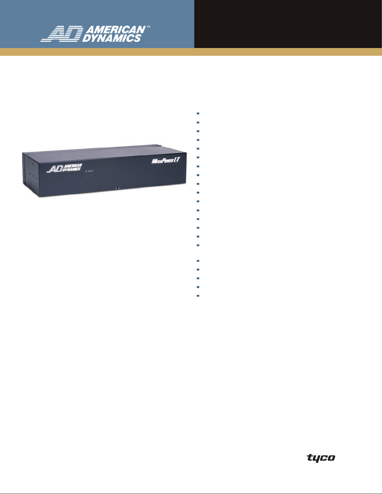
MegaPower LT
Matrix Switcher/Controller System
Features That Make a Difference:
DirectSet function allows dome settings to be easily changed
128 views (camera/preset and camera/pattern)
16 sequences/tours
ADnet (RS-485) and RS-232 communication protocols
Supports up to eight keyboards with priority settings
Password protection for menu entry
Network up to three matrix systems on an ADnet (RS-485) bus
Dome ping test
System partitioning
Video loss detection on all channels
Alarm titles
Five alarm display modes
Three alarm response modes
Send alarm messages to other networked matrix systems
255 event messages
Embedded menu support for English, French, Spanish, German
and Italian
16 x 4 or 32 x 8 models
Looping inputs, auto terminated
Supports SensorNet or AD-Up-The-Cable (AD-UTC) dome protocols
Controls RS-422 domes using the SensorNet to RS-422 converter
Supports FSK coaxial telemetry
American Dynamics™ MegaPower LT matrix switcher systems
are designed to satisfy the needs of small scale installations.
The system is available in 16 and 32 input models and
supports American Dynamics MegaPower 1100, ADTTE,
AD2089, and ControlCenter 200 and 300 keyboards.
MegaPower LT is fully compatible with the SpeedDome series
of programmable dome cameras. It supports the
highly reliable ADnet RS-485 communication protocol as
well as SensorNet and digital AD-Up-The-Cable (AD-UTC)
protocols. These protocols enable you to “ping” the dome to
verify communication. In addition, the DirectSet feature
allows you to quickly change dome camera settings.
MegaPower LT supports standard dome features such as
presets, patterns and auxiliaries as well as “views,” which
allow an operator to call a camera/preset or camera/pattern
with a single command.
This small versatile system can be mounted virtually
anywhere—in racks, on walls or even under a desk. It
supports the robust features you would typically expect in a
high-end system including partitioning, priorities, sequences;
and includes a robust alarm-handling package. In addition,
you can network up to three MegaPower LT systems to form
a distributed system. MegaPower LT is also easily integrated
with other security system components through the
American Dynamics standard RS-232 keyboard protocol.
Page 2

features
Multiple Mounting Options
MegaPower LT is provided with mounting ears that can be
attached to the unit in multiple orientations to enable desk,
wall or rack mounting.
System Configuration
Modular, high-density system with a choice of 16 video
inputs and 4 video outputs or 32 video inputs and 8 video
outputs.
Camera Site Control
Users can control fixed and variable-speed domes, auxiliary
outputs, presets and patterns at suitably equipped camera
sites via the SensorNet outputs and the AD-UTC protocol.
Each input is independently configurable.
System Programming
On-screen menus enable use of any full-system keyboard
to program system features. Menu access is passcode
protected to prevent unauthorized access.
Passcode Menu Access
Two levels of menu access are provided, administrator and
supervisor. Only administrator access provides access to the
alarm and installer menus.
Time and Date
Administrators can set the display to a 12 or 24-hour clock.
Three date formats are provided:
• MM/DD/YY
• YY/MM/DD
• DD/MM/YY
In addition, the daylight savings time option enables the
clock to be adjusted forward, backward, or no action.
Views
Program up to 128 views, each with a camera input number
and either a preset number or a pattern number. Each view
can be given a unique title, which replaces the camera title
on the monitor display when selected either manually or as
part of a sequence.
Tours (Sequences)
Sixteen tours of video inputs may be established for call-up
to monitors at anytime. Each tour provides 16 positions for
insertion of video inputs and views — each with an individual
dwell time. Tours can be run forward or in reverse. They can
include the same video input multiple times and/or multiple
presets and patterns from a single camera. Two tours can be
connected together to provide up to 32 entries. Video inputs
partitioned from a monitor are automatically skipped.
ADnet (RS-485) Communications
One RJ-45 connector allows standard communication with
keyboards, other MegaPower LT systems and other ADnet
devices. The port is programmable for data rates of 9.6k and
19.2k baud.
RS-232 Communications
The RJ-45 connector simultaneously supports RS-232
communications as well as ADnet. The port can expand to
4 ports with an optional port expander. This expands the
available RS-232 ports to a maximum of 4.
Selectable On-Screen Text
Each of the monitors can display the date/time, video input
number, monitor number, 16-character user-definable video
input or view title, alarm message and event message. White
character on-screen text with black outline optimizes viewing
on diverse contrast scenes. The user can turn each of the
displays on and off. In addition, users can select the line on
which each of the titles will appear.
Recorder Control (DirectControl)
With the ControlCenter 200 and 300 keyboards in ADnet
mode, users can control standard recorder functions
directly — play, stop, pause, record, rewind, fast forward,
eject — for both RS-232 controlled VCRs and digital recorders.
Users can customize the keyboards to support different
command sets.
Automatic Alarm Call-Up
Alarm inputs can be programmed to call any video input
to any one or more video outputs. For each alarm or
event, users can define a camera, preset, alarm title, event
message, keyboard sound level and/or auxiliary action.
Each monitor can be configured to display alarms. After
an alarm is cleared, the monitor can either display the last
alarm response or be returned to its pre-alarm state. The
global alarm settings have 5 display modes and 3 clearance
modes.
Alarm Display Modes
• None: No change to the monitor display.
If multiple alarms are received, the last alarm received
• Last:
is displayed until it is cleared.
• Stack:
• Switch:
• Rotate:
If multiple alarms are received, the alarms are
displayed on additional alarm enabled monitors. Additional
alarms are held in a queue of up to 255 events and 32
alarm inputs.
The first alarm in will be displayed on all alarm
monitors. Additional alarms will display on all alarm monitors
once the preceding alarm is cleared.
The first alarm in will be displayed on all alarm
monitors. Additional alarms will sequence in a pre-defined
dwell time (time-out) on all alarm monitors until
acknowledged. Alarm outputs are disabled in this mode.
Page 3

Alarm Clearance Methods
• Acknowledge: Alarms must be manually acknowledged.
• Time Out:
Alarms are automatically cleared after a
pre-defined dwell time of 2 to 99 seconds. Alarms can also
be manually acknowledged.
• Transparent:
Alarms are cleared after the alarm contact
returns to its neutral state. If the contact returns to this state
before the transparent dwell time of 2 to 99 seconds, then
the alarm remains active for that predefined period. Alarms
can also be manually acknowledged.
Events
An event is a message that is passed from one matrix to
itself or other matrix systems (up to 3 on an ADnet network).
Up to 255 events can be defined and each system can have
a predefined event response. In addition, events can be
generated from any ControlCenter 200 or 300 keyboard to
produce a system response.
DirectSet
1
Allows the operator to quickly access and change dome
camera settings either via an on-screen selection or simple
keyboard command, without the need to access the dome
menus. Features like wide dynamic range, day/night and
dome information screens can be easily accessed without
compromising other dome settings.
Dome Ping
This utility allows the administrator to verify the integrity of
the communication between the matrix and the dome on
both SensorNet and the AD-UTC protocol.
Internal Video Loss Detection
Video loss detection is standard on all video inputs. If such
a camera is selected, a red screen will appear with a “Video
Loss Camera” message.
System Partitioning
Defining authorized access to keyboards, video inputs and
video outputs further enhances system flexibility. System
partitioning includes the following:
• Keyboard-to-Monitor Access: Restricts selected
keyboards from accessing selected video outputs.
• Keyboard-to-Camera Access:
Restricts selected
keyboards from calling or controlling selected video inputs.
• Keyboard-to-Camera Control Access:
Allows selected
keyboards to view certain cameras but restricts those
keyboards from controlling the cameras.
Keyboard Priority Operation
Keyboards can be assigned one of 8 levels of priority control
of remote camera sites. Level 1 has highest priority for
control of cameras. Up to 4 keyboards may simultaneously
control PTZ devices.
Model Numbers
ADMPLT16 . . . . . . . . . . . . MegaPower LT, 16 inputs x 4 outputs,
ADMPLT16C2 . . . . . . . . . . MegaPower LT, 16 inputs x 4 outputs,
ADMPLT16C3 . . . . . . . . . . MegaPower LT, 16 inputs x 4 outputs,
ADMPLT32 . . . . . . . . . . . . MegaPower LT, 32 inputs x 8 outputs,
ADMPLT32C2 . . . . . . . . . . MegaPower LT, 32 inputs x 8 outputs,
ADMPLT32C3 . . . . . . . . . . MegaPower LT, 32 inputs x 8 outputs,
(120/230 VAC, NTSC/PAL)
(120/230 VAC, NTSC/PAL) with
ControlCenter 200 keyboard
(120/230 VAC, NTSC/PAL) with
ControlCenter 300 keyboard
(120/230 VAC, NTSC/PAL)
(120/230 VAC, NTSC/PAL) with
ControlCenter 200 keyboard
(120/230 VAC, NTSC/PAL) with
ControlCenter 300 keyboard
On-Board Diagnostics
Built-in diagnostics allow the user to determine the status of
the system’s internal components. LEDs on the front of the
unit clearly indicate power status and system health.
Optional Accessories
Accessory Description
ADCC0200,
ADCC0300
ControlCenter
Keyboards
ADCC1100
MegaPower
ControlCenter
Keyboard
ADTTE Touch Tracker
Keyboard
AD2088 and AD2089
Keyboards
AD2081, AD2081-1
Port Expander
RCSN422, SensorNetto-RS-422 Converter
ADACTP01BNC
Twisted Pair Video
Adapter
VRCMKIT Cable
Brackets
Full system keyboards allow for video switching,
pan/tilt control, dome control, auxiliary control,
recorder control, multiplexer control and system
programming. The keyboards support bi-directional
communication with the matrix via ADnet.
Full system, smart card enabled keyboards allow
for video switching, pan/tilt control, dome control,
auxiliary control, macro control, user partitioning and
access, recorder control and system programming.
The keyboards support bi-directional communication
with the CPU via RS-232 ASCII commands.
Full system keyboards allow for video switching, pan/
tilt control, dome control, auxiliary control and system
programming. The keyboards support bi-directional
communication with the CPU via RS-232 ASCII.
Full system keyboards allow for video switching, pan/
tilt control, dome control, auxiliary control, macro
control, recorder control, and system programming.
The keyboards support bi-directional communication
with the CPU via RS-232 ASCII commands.
Expands one RS-232 port on a system into 4 ports.
This provides connections to multiple system
keyboards.
Control of RS-422 domes using the RCSN422
SensorNet-to-RS-422 converter.
A passive transmission device that transmits video
or video with Up-The-Cable (AD-UTC) dome control
signals over Unshielded Twisted Pair (UTP) cables,
point-to-point, for distances up to 300 m (1,000 ft)2.
These adapters use Category 2-6 twisted pair wires
to transmit the video and dome control signals
and do not require power.
Each kit contains 3 cable management brackets.
(1) Supported by SpeedDome Ultra VII or SpeedDome Ultra 8.
(2) Some digital video recorders, video servers, or similar products may lose color information when UTP cable distances exceed 180 m (600 ft).
Page 4

S P E C I F I C A T I O N S
Basic System Diagram
Video Outputs
Video Outputs
Fixed Cam eras,
Fixed Cam eras,
SpeedD omes or
SpeedD omes or
Mini-Domes
Mini-Domes
MegaPower 1100,
MegaPower 1100,
Control Center 200 and 300,
Control Center 200 and 300,
ADTTE, & AD2089 Keybo ards
ADTTE, & AD2089 Keybo ards
Alarm In puts
Alarm In puts
Intellex
Intellex
RS-232 Inpu ts
RS-232 Inpu ts
MegaPower LT
MegaPower LT
AD100 Serie s Recorder
AD100 Serie s Recorder
Control D evices
Control D evices
Operational
Number of Video Inputs . . . .16 or 32
Number of Video Outputs. . . 4 (ADMPLT16)
8 (ADMPLT32)
Bandwidth . . . . . . . . . . . . . .6 MHz
S/N Ratio . . . . . . . . . . . . . . .60 dB (Vp-p vs. Vrms noise)
Crosstalk
Adjacent Channels . . . . . . . .-45 dB (at 3.58 MHz)
Input to Input . . . . . . . . . . . .-55 dB (at 3.58 MHz)
Differential Delay. . . . . . . . . .±1.0°
Differential Phase . . . . . . . . .≤0.5°
Differential Gain . . . . . . . . . .≤1.5%
Tilt . . . . . . . . . . . . . . . . . . . . .≤0.5%
Gain . . . . . . . . . . . . . . . . . . .Unity ±1 dB
Return Loss
Input/Output . . . . . . . . . . . . .≥40 dB
DC Level (Video Signal) . . . .0 Volts (±0.1 V typical)
Switching . . . . . . . . . . . . . . . Complete switching of crosspoint matrix
Switching Speed. . . . . . . . . .Less than 20 ms (typical)
Non-Volatile Memory . . . . . . Setup information saved for a minimum
EIA RS-170 and NTSC, CCIR and PAL
of 5 years
Connectors
Video Inputs . . . . . . . . . . . . . 16 or 32, looping 0.5 to 2.0 Vp-p,
Video Outputs. . . . . . . . . . . . 4 or 8 1.0 Vp-p, BNC composite
RS-485/RS-232 . . . . . . . . . . One 8-pin Modular RJ-45 jack (expandable)
SensorNet. . . . . . . . . . . . . . . 1 port, 1 connector (16 inputs) or 2 ports,
Alarm Inputs . . . . . . . . . . . . . 4 Connectors (16 inputs) or 8 connectors,
Relay Outputs . . . . . . . . . . . . 1 connector, 1 output (16 inputs) or
BNC composite
Optional Port Expander extends the RS-232
port to 4
2 connectors (32 inputs) through 5-pin
pluggable Eurostyle terminal screw connectors
(32 inputs) through 5-pin pluggable
Eurostyle terminal screw connectors
2 connectors, 2 outputs (32 inputs)
Form-C relays through 3-pin Eurostyle
terminal screw connectors
Communication
SensorNet. . . . . . . . . . . . . . . 32 devices per port at a maximum distance of
ADnet . . . . . . . . . . . . . . . . . . 16 devices at a maximum distance of 1.2 km
AD-UTC . . . . . . . . . . . . . . . . 700 m (2,300 ft) on 20 AWG RG59/U coax
FSK Telemetry . . . . . . . . . . . 350 m on 20 AWG RG59/U coax — Baxall, Vista
1 km (3,000 ft) on one 22 AWG unshielded
twisted pair (UTP)
(3,900 ft) on shielded/screened Cat5 wire
or better or Belden 8761 or equivalent
(Belden 8281 or equivalent) or URM70 cable
and Dennard domes (via DAX)
3
Electrical
Input Voltage. . . . . . . . . . . . .Regulated, 12 VDC ±10%
Power Supply . . . . . . . . . . . . 12 VDC ±10%, 2 A, 2.1 mm pin-jack,
positive center conductor
Mechanical
Dimensions (H x W x D) . . . .90 x 445 x 185 mm (3.5 x 17.5 x 7.3 in)
Unit Weight . . . . . . . . . . . . . .3.5 kg (7.7 lbs)
Shipping Weight . . . . . . . . . .4.7 kg (10.4 lbs)
Color . . . . . . . . . . . . . . . . . . .Black
Environmental
Temperature
Operating Temperature. . . . .0° to 40°C (0° to 104°F)
Storage . . . . . . . . . . . . . . . . .-20° to 60°C (-4° to 140°F)
Humidity . . . . . . . . . . . . . . . .10% to 95% RH, noncondensing
Regulatory
Emissions . . . . . . . . . . . . . . . FCC Part 15, Subpart B, Class A
Immunity . . . . . . . . . . . . . . . .EN50130-4
Safety . . . . . . . . . . . . . . . . . . UL and CUL 1950
EN50081-1
EN60950
(3) This distance is for the AD-UTC data only. See cable manufacturers specifications for video capabilities
Product offerings and specifications are subject to change without notice. Actual products may vary from photos. Not all products include all features. Availability
varies by region; contact your sales representative. Certain product names mentioned herein may be trade names and/or registered trademarks of other companies.
© 2007 Sensormatic Electronics Corporation. All rights reserved. AD0103-DS-200710-R01-LT-EN
www.americandynamics.net
 Loading...