

Page 1

MegaPower® CPU
ADMPCPU
Operator’s Guide
8200-0421-02 E
Page 2

Page 3
MegaPower® CPU
A
Operator’s Guide
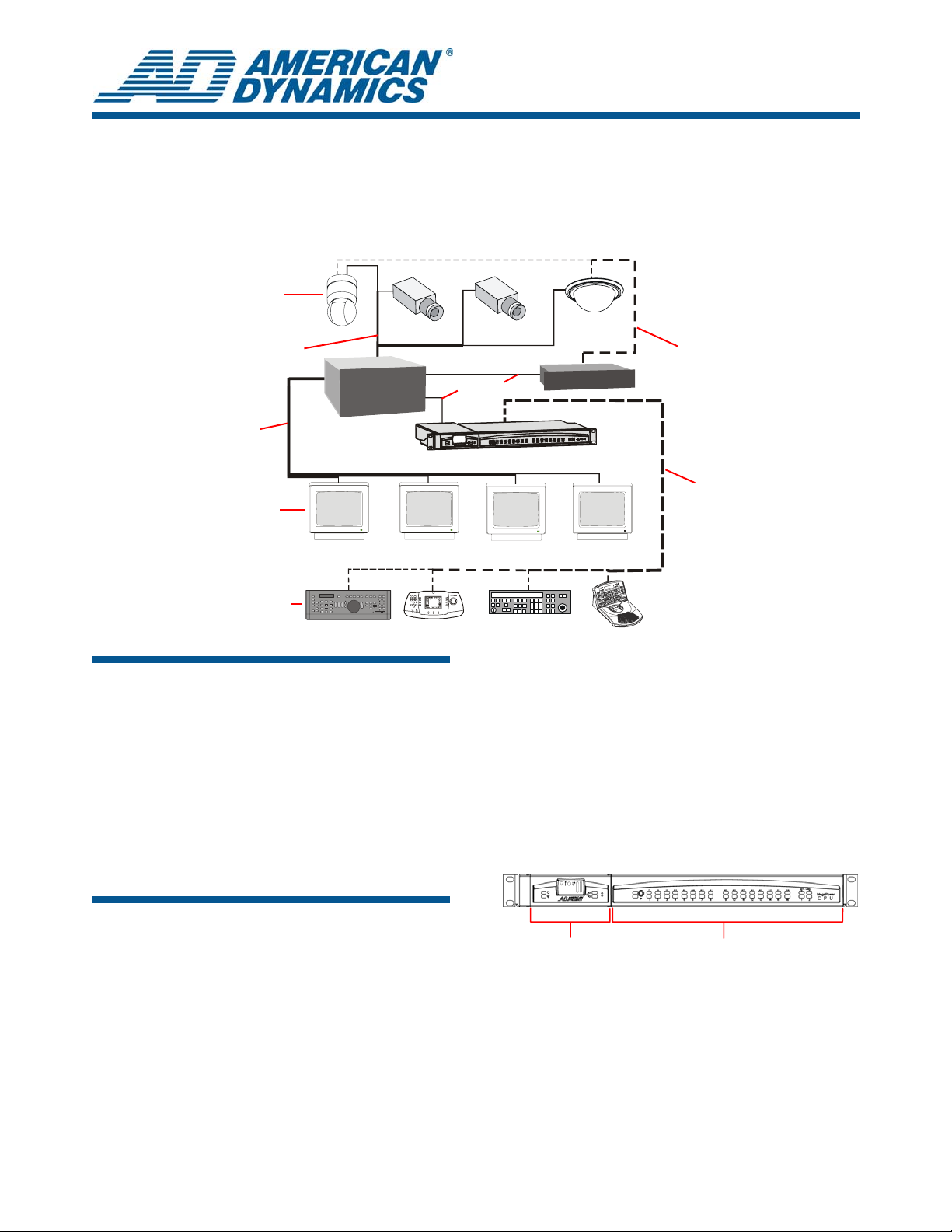
Figure 1. MegaPower 3200 Video-Matrix Closed-Circuit Television (CCTV) System
Cameras
Cameras
Video
Video
Monitors
Keyboards
Matrix
Switcher Bay
About this Guide
This Operator’s Guide provides information about
operating the MegaPower 3200 video-matrix
closed-circuit television (CCTV) system.
Another related document is the MegaPower CPU
Administrator’s Guide, 8200-0421-03.
If you need assistance...
Contact Technical Support.
DDL*
MegaPower CPU
The MegaPower CPU (
following major modules:
• MPU (Multiple Purpose Unit): controls system
operation, provides Ethernet and video data
connections, image capture, input power, and
dome/PTZ (pan, tilt, zoom) connections.
• Port Module: provides RS-232 communications
ports, high-speed data lines, and alarm relay
connections.
Figure 2. MegaPower CPU
Data
Protocol
Devices
Data
*ADDL = AD Data Line
Figure 2) consists of the
About the Product
The MegaPower CPU (Central Processing Unit) is
the control unit for the MegaPower 3200 video-
MPU Port Module
matrix CCTV switcher. It enables the setup and
control of cameras, monitors, users, alarms, video
recording, and data communications.
© 2008 Sensormatic Electronics Corp.
MEGAPOWER CPU 8200-0421-02, REV. E
OPERATOR’S GUIDE
1 of 21
Page 4

Contents
About this Guide ............................................................ 1
About the Product.......................................................... 1
MegaPower 3200 Video-Matrix CCTV System Overview
.......................................................................................
System Features .................................................... 2
System Components .............................................. 3
Satellite Configuration Overview............................. 3
Operator Tasks....................................................... 3
Compatible System Keyboards .............................. 3
Recording Functions............................................... 4
Operating the MegaPower System ................................ 4
Entering Passcodes................................................ 4
Selecting a Monitor................................................. 4
Using the Monitor Display....................................... 4
Calling a Camera.................................................... 5
Locking a Camera .................................................. 5
Controlling Camera Pan/Tilt/Zoom ......................... 5
Controlling Camera Focus...................................... 5
Controlling the Camera Iris ..................................... 5
Calling Presets ....................................................... 5
Running Patterns.................................................... 6
Running Tours ........................................................ 6
Holding a Tour ........................................................ 6
Calling Salvos......................................................... 6
Working with Alarms............................................... 6
Arming Monitors ..................................................... 7
Displaying Alarms................................................... 7
Alarm Queuing Methods......................................... 7
Alarm Clearing Methods ......................................... 7
Controlling Auxiliaries ............................................. 7
Viewing Satellite Sites ............................................ 8
Performing a Ping Test........................................... 8
Declarations................................................................... 9
Appendix A: Keyboard Commands for AD2088 /
AD2089* ......................................................................
Operator Functions............................................... 10
Programming Functions ....................................... 11
Appendix B: Keyboard Commands for ADCC1100...... 12
Operator Functions............................................... 12
Programming Functions ....................................... 14
Appendix C: Keyboard Commands for ADCC0200/0300
.....................................................................................
Operator Functions............................................... 15
Programming Functions ....................................... 17
Appendix D: Keyboard Commands for ADTTE............ 18
Operator Functions............................................... 18
Programming Functions ....................................... 19
Appendix E: Auxiliary Key Code Functions.................. 20
F1 Special Function Keys..................................... 20
F2 Special Function Keys..................................... 20
10
15
MegaPower 3200 VideoMatrix CCTV System
Overview
2
The MegaPower CPU is part of the video-matrix
switcher system and is capable of managing
cameras, monitors, alarm events, and video
recording at both local and satellite (remote) sites.
The MegaPower 3200 video-matrix CCTV system
can respond to alarms and perform auxiliary
switching for the control of gates, doors, lights, and
other output devices. Depending on the control
requirements of a given application, various
operator keyboards and accessory devices also
can be used with the system.
System Features
• Full matrix-switching capability
• Tours
• Salvos
• Timed events
• Alarm response
• Camera alarm programming
• Monitor alarm programming
• System status display
• Input identification
• User-assigned camera numbers
• Selectable date/time display
• External control inputs
• Output controls
• System security
• Partitioning
• Control over 3,200 local cameras and 256
monitors
• SensorNet support for up to 508 cameras
• Support for up to 30 satellite sites
• Control up to 96,000 remote cameras
• Control up to 38,528 remote cameras (full
crosspoint connection) to 256 monitors
• Memory retention
• EASY (Enhanced Administration SYstem) CPU
software
MEGAPOWER CPU 8200-0421-02, REV. E
OPERATOR’S GUIDE
2 of 21
Page 5

System Components
MegaPower 3200 video-matrix CCTV systems can
operate with a variety of components to meet the
video surveillance goals of the organization.
System components can include:
• The MegaPower CPU
• Camera/monitor switching bays
• Fixed cameras, pan/tilt/zoom cameras, and
dome cameras
• Video monitors
• Operator keyboards
• Video recording devices
• Alarm interface units
• Video loss detection
• Auxiliary devices, such as locks, lights, and
alarms
• Programming PC
• Satellite site connections
• Protocol devices
Satellite Configuration Overview
The MegaPower CPU allows local operators to
access cameras and monitors located at satellite
(remote) sites.
• Site refers to a single MegaPower CPU in a
satellite network and the resources that are
directly connected and accessible to it.
• Local refers to features that are accessible
within a single site by the keyboard attached to
that site’s MegaPower CPU.
• Remote refers to features of other MegaPower
CPU sites in a satellite network that are
accessible from the local MegaPower 3200
video-matrix CCTV system.
Each site is assigned a site number for
identification purposes. Operators use site
numbers to switch from controlling local video
functions to controlling video functions at satellite
sites.
cameras, create and run automated camera
actions, acknowledge alarm activities, adjust
monitors, and perform other functions as needed.
Typical operator control functions include:
• Keyboard passcode entry
• Video selection of local monitors and cameras
• Video selection of remote sites and cameras
• Controlling cameras (panning, tilting, and
zooming)
• Activating presets and auxiliaries
• Running tours
• Running patterns
• Calling salvos
• Acknowledging alarms
Operators also create many of the automated
features that make the MegaPower CPU a
powerful, yet easy-to-use, CCTV surveillance
system. Operators can program the following
functions:
• Preset scenes
• Tours
• Patterns
• Alarming monitors
Operators also can arm monitors for use in
managing alarm response.
Compatible System Keyboards
MegaPower CPU video switching and control
capabilities are provided by American Dynamics
keyboards. These capabilities are “monitor
oriented” in that a keyboard controls only those
functions associated with the monitor under control
of that keyboard.
The MegaPower CPU is compatible with the
following keyboards:
• AD2078A
• AD2079
• AD2088
• AD2089 (see note)
• ADCC0200
• ADCC0300
• ADCC1100
• ADTTE
Operator Tasks
The MegaPower 3200 video-matrix CCTV system
is configured by a system administrator via
software on a personal computer. The system
administrator is usually a manager-level or higher
individual who will create privilege levels for
operators.
Operators perform the day-to-day task of video
surveillance using keyboards connected to the
MegaPower CPU. They select and control
MEGAPOWER CPU 8200-0421-02, REV. E
OPERATOR’S GUIDE
3 of 21
Note: When the AD2089 keyboard is connected
directly to the MegaPower CPU, the DVR functions
are not supported.
Keyboard control functions for your keyboard are
found in the appendices at the end of this guide.
For step-by-step instructions on using these
keyboards with your MegaPower 3200 video-matrix
CCTV system, refer to the appropriate keyboard
manual.
Page 6

Recording Functions
Operating the MegaPower
AD2088 Keyboard
The AD2088 keyboard is capable of implementing
VCR (video-cassette recorder) control by the
operator selecting the VCR operating mode and
pressing any one of seven VCR control keys:
• Play • Fast-Forward
• Stop • Rewind
• Record • Eject
• Pause
For more information on the VCR control function
of the keyboard, refer to the VCR Mode function in
Appendix A: Keyboard Commands for AD2088 on
10.
page
ADCC0200/0300 Keyboard
The ADCC0200/0300 keyboard is capable of
implementing VCR control by the operator
selecting the VCR operating mode and pressing
any one of six VCR control keys:
• Play • Pause
• Stop • Fast Forward
• Record • Rewind
For more information on the VCR control function
of the keyboard, refer to the VCR Mode function in
Appendix C: Keyboard Commands for
ADCC0200/0300 on page
15.
ADCC1100 Keyboard
System
Note: Consult the Appendix section of this Guide
or the Operator’s Guide that came with your
keyboard for step-by-step instructions on how to
perform the functions described in this section.
Entering Passcodes
Passcodes can be assigned to keyboards to
prevent unauthorized access to video controls. If
passcodes are implemented, operators will be
required to logon to the keyboard. Depending on
the keyboard, both a user ID and a passcode may
be required to begin operations.
Selecting a Monitor
Monitors display the video from the cameras and
domes in the system. Operators must select a
monitor before they can control cameras or
perform other surveillance activities.
Operators are free to switch monitors as needed.
For example, suppose that while operating on one
monitor, another monitor begins displaying an
alarm. The operator must switch to the alarming
monitor in order to handle the alarm event.
To select a monitor, the operator enters the
monitor’s unique identification number into the
keyboard according to the keyboard’s operating
instructions. The monitor access is determined by
the system administrator and provided to
operators.
The ADCC1100 keyboard is capable of
implementing VCR control by the operator using
the following VCR control keys:
• Play • Pause
• Stop • Fast Forward
• Record • Rewind
• Eject
For more information on the VCR control function
of the ADCC1100 keyboard, refer to the
ADCC1100 Keyboard Installation and Operation
Instructions, ADCC1100-HB-2.
MEGAPOWER CPU 8200-0421-02, REV. E
OPERATOR’S GUIDE
4 of 21
Using the Monitor Display
The monitor displays text on the screen as a
reference for operators. The text displays the
number of the currently called cameras, the
camera title, the current date, and the time of day
Figure 3). The status line shows information about
(
alarm conditions, tour dwell time, or camera status.
The brightness, position, and whether or not the
camera title/monitor status and the time and date
are displayed can be changed on a monitor-tomonitor basis according to the operator’s
preference.
Page 7

Figure 3. Local monitor screen display
a
b
0001
HOLD
MAIN
ENTRANCE
c
12-15-04
10:27:56
a. Camera Number
b. Monitor/Camera Status Indicator
c. Camera Title
d. Current Date
e. Current Time
• Tilt is the up and down movement of the
camera.
• Zoom is the ability to move the camera’s view
closer to or farther away from an object.
The speed at which cameras with variable speed
capability can pan or tilt is determined by how far
the operator moves the joystick in any given
direction. The further the joystick is pushed in one
direction, the faster the camera will pan or tilt.
d
e
Controlling Camera Focus
Focus refers to the action of adjusting the clarity of
the camera image on the monitor. Keyboards
provide manual focus controls even though many
cameras have auto-focus capability. Manual focus
is sometimes needed when zooming in or out on a
camera.
Calling a Camera
After a monitor has been selected for control of the
keyboard, the operator can “call” a camera to view
and control. Each camera in the system is
identified by a unique number that is used when
calling it. It is necessary to call cameras for certain
programming functions as well.
Locking a Camera
After calling a camera to a monitor, an operator
can lock the camera to prevent other operators
from taking control of it. This feature can be
particularly important when actively following a
suspect or investigating an area of interest.
When another operator calls a locked-out camera,
the designated camera video displays on the
monitor, but will not respond to that operator’s
controls. The message, “LCK KXX,” (where XX is
the number of the keyboard that has the locked-out
camera) is displayed on the monitor to let the
operator know the camera is locked out.
The default status of all cameras is unlocked.
Controlling Camera Pan/Tilt/Zoom
Operators can control the pan/tilt/zoom (PTZ)
movements of motorized cameras and domes
using the joystick or a similar device on the
keyboard.
• Pan is the side-to-side movement of the
camera.
Controlling the Camera Iris
Normally, the brightness of the camera’s picture is
adequately controlled by the camera’s auto iris or
similar feature. However, at times the operator may
want to manually adjust the iris to brighten or
darken the scene to improve the camera’s view.
Opening the iris brightens the scene while closing
the iris darkens the scene. For example, an
operator may want to open the iris to see details of
a person who suddenly steps in front of a brightly lit
window. Conversely, the operator may close the
iris to darken the scene when panning a camera
from a dark area to a bright area.
Calling Presets
A preset is a memorized location or scene that a
pan/tilt camera can display on operator demand.
Presets are also referred to as shots or targets.
The MegaPower CPU allows up to 96 presets per
camera with a suitably equipped dome/PTZ device.
Every preset is identified by a unique number that
is used when calling it.
Notes:
• If a preset number is called and no preset scene
is programmed for that camera, the pan/tilt may
attempt to move to an undefined scene and
camera movement may be unexpected.
• Operators can program presets while in the
keyboard’s Program mode.
MEGAPOWER CPU 8200-0421-02, REV. E
OPERATOR’S GUIDE
5 of 21
Page 8

Running Patterns
A pattern is a sequential series of pan/tilt/zoom
and focus commands defined for a SpeedDomeseries camera. Patterns can provide a convenient,
automated, and continuous surveillance of a large
area using only one camera.
Every pattern is identified by a unique number that
is used when running it.
Patterns are created in real time, which means that
the dome remembers each pattern segment in the
actual time it takes the operator to execute a
command. For example, if the operator holds a
dome on a door for 30 seconds during
programming, the door scene will appear for 30
seconds when the pattern runs. Patterns also can
include stops (or pauses).
SpeedDome, SpeedDome Optima, and
SpeedDome Ultra (prior to VIIE) cameras can
generate three patterns each. SpeedDome Ultra
VIIE cameras can generate a maximum of 16
patterns. Consult your camera dome
documentation for further information.
Note: Operators can program patterns while in the
keyboard’s Program mode.
Running Tours
Every system tour is identified by a unique number
that is used when running it.
Holding a Tour
Tours can be stopped temporarily on a single
camera entry and then restarted going forward or
in reverse. Holding a tour can give the operator
additional time to study a particular scene.
While a tour is on hold, all keyboard control actions
(pan, tilt, lens adjustment, and auxiliary on/off
functions) can be performed on the held camera.
Calling Salvos
A salvo is a group of cameras that can be called
for simultaneous display on a contiguous group of
monitors. If more cameras exist in a salvo than
there are monitors to display them, the cameras at
the end of the salvo will not be seen.
Salvos often are used to see a large area all at
once from the vantage point of several cameras in
that area; for example, a parking garage with
cameras installed in all four corners.
Every salvo is identified by a unique number that is
used when calling it.
A monitor tour is a sequential display of several
different camera views on a monitor. Monitor tours
provide an effective way to see multiple areas
around a facility by automatically switching to
different cameras.
The MegaPower CPU is capable of displaying up
to 64 different camera views in a single tour. Each
camera view is displayed for a defined period of
time (dwell time) before switching to the next
camera.
Monitor tours can be modified while they are
running to add a camera, remove a camera, or reprogram a camera.
Note: Operators can program monitor tours while
in the keyboard’s Program mode.
System tours, which are created by administrators
using the EASY CPU configuration and monitoring
software, supersede monitors tours. When a
system tour is started on a monitor, it will erase any
monitor tour currently programmed for that monitor.
After a system tour is called to a monitor, it can be
altered and saved as a monitor tour. The original
system tour will not be erased.
Working with Alarms
The MegaPower CPU can associate alarm devices
with cameras so that video of important areas will
be displayed on one or more monitors when an
alarm occurs. The video on display can be a tour, a
salvo, a preset, or a pattern. In addition to video,
the monitor will display the word “ALARM.” It is the
responsibility of operators to respond appropriately
when alarms occur.
Note: If a salvo is called in response to an alarm,
the monitor displaying the first camera of the salvo
will show the word “ALARM,” and the monitors
displaying the remaining cameras of the salvo will
show the word “SALVO.”
Up to 128 unique titles can be defined for display
on alarming monitors or sent as e-mail messages.
Up to 16 e-mail messages can be defined and
assigned to alarm numbers to send when alarms
occur.
MEGAPOWER CPU 8200-0421-02, REV. E
OPERATOR’S GUIDE
6 of 21
Page 9

Arming Monitors
Monitors must be “armed” in order to display
alarms. Arming a monitor defines how it will
display, queue, and clear incoming alarms. Monitor
Arming is available at local sites only.
Note: Operators can arm monitors while in the
keyboard’s Program mode.
Displaying Alarms
The MegaPower CPU provides three methods of
displaying alarms:
• Single Display – incoming alarms are
displayed on a single monitor. Multiple alarms
received at a single monitor will be either
sequenced or held based on the monitor’s
alarm queuing method.
• Dual Display – incoming alarms are displayed
on a pair of monitors. The monitor that receives
the first of a series of alarms is called the hold
monitor. Subsequent alarms are received and
queued at the second, or sequence, monitor.
After an alarm is cleared on the hold monitor,
the first alarm in queue on the sequence
monitor is moved to the hold monitor until
cleared.
• Hold Queuing – an incoming alarm is
displayed and held on an armed monitor until it
is cleared. All subsequent alarms are queued in
order until the current held alarm is cleared.
Alarm Clearing Methods
Alarms are cleared by three different methods:
• Manual clear – an alarm is cleared by a system
operator’s keyboard command.
• Instant Clear – an alarm is reset immediately at
its source. For example, a door opens and
activates an alarm. Closing the door clears the
alarm instantly.
• Auto Clear – an alarm is reset at its source
after a 20-second delay (if not manually
acknowledged sooner). For example, a door
opens and activates an alarm. Then, the door is
immediately closed. In this case, the alarm will
not clear until the door remains closed for a 20second interval.
CAUTION: Do not arm any monitor output that is
used as a video trunk output to a satellite site.
Monitor arming cannot be changed for any monitor
that has active alarms.
• Block Display – incoming alarms are displayed
on a block (group) of monitors with which they
are associated. The first incoming alarm is
displayed on the first (lowest numbered)
monitor of the block. The second alarm is
displayed on the next lowest numbered monitor
of the block, and so on. When all monitors in a
given block are displaying alarm video signals,
all subsequent alarms are either held in queue
or sequenced until the displayed alarms are
cleared depending on the monitor alarm
queuing method.
Alarm Queuing Methods
Alarm queuing determines how the MegaPower
CPU handles multiple incoming alarms:
• Sequence Queuing – incoming alarms are
displayed in sequence at an armed monitor and
will cycle continuously until each is cleared.
Each alarm will be displayed for a preprogrammed dwell time before it is succeeded
by the next received alarm.
Controlling Auxiliaries
An auxiliary is a device, such as a light, audible
alarm, or door lock, that can be controlled from a
keyboard. For example, an operator could turn on
a light in a room with a camera in it, turn off an
alarm siren, or unlock a door for a guard to enter a
room.
Auxiliaries are classified as either momentary or
latched.
• A momentary auxiliary remains active as long
as its control button is pressed and held; for
example, holding down the button to unlock a
door until the guard passes through the
doorway, then releasing the button to lock the
door.
• A latched auxiliary remains active until it is
deactivated; for example, pressing a button to
turn on a light, then pressing it again to turn off
the light.
MEGAPOWER CPU 8200-0421-02, REV. E
OPERATOR’S GUIDE
7 of 21
Page 10

Viewing Satellite Sites
Performing a Ping Test
Satellite sites are locations where other
MegaPower 3200 video-matrix CCTV systems
are in operation and are accessible from the
local MegaPower system. Local operators can
access and control cameras at satellite sites.
When a satellite site is accessed, the monitor
display changes to include text relevant to the
satellite site (see
Figure 4).
A local MegaPower 3200 video-matrix CCTV
system can access up to 30 satellite sites.
Figure 4. Remote monitor screen display
SITE
e
BUSY
f
LOCTN B
BLDG 2
12-15-04
11:27:56
g
A ping test checks and verifies the state of
communications between camera domes and the
MegaPower CPU. The ping test also reports
configuration information from the camera dome for
display on the EASY CPU camera status screen.
To initiate a ping test, enter the special function key
29-F1 on your keyboard. Refer to
Auxiliary Key Code Functions on page
Appendix E:
20 for a
listing of keyboard special function keys.
• At the start of a ping test, the mnemonic and
flash version number data are displayed on a
selected monitor for a few seconds before the
ping test data is collected and displayed for the
remainder of the test.
• As the test progresses, the monitor displays the
number of transmission attempts and the
number of failure counts (up to 6 digits) of the
attempts that failed to receive a reply from the
dome.
A ping test allows concurrent testing of up to ten
domes to different monitors.
a
0001
b
HOLD
MAIN
ENTRANCE
c
a. Remote camera number
b. Remote monitor/camera status
c. Remote camera title
d. Remote date/time
e. Remote site status
f. Remote site title
g. Local date/time
12-15-04
10:27:56
d
MEGAPOWER CPU 8200-0421-02, REV. E
OPERATOR’S GUIDE
8 of 21
Page 11

Other Declarations
Declarations
Regulatory Compliance
EMC........................................................47 CFR, Part 15
EN 50130-4
EN 55022
EN 61000-3-2
EN 61000-3-3
Safety ........................... UL/IEC/EN/CSA C22.2. 60950-1
Environmental..................................... RoHS 2002/95/EC
WEEE 2002/96/EC
IP code X0
Regulatory Type:
ADMPCPU-MPU
ADMPCPU-PORT
ADMPCPU-TRAY
FCC COMPLIANCE: This equipment has been tested and
found to comply with the limits for a Class A digital device,
pursuant to part 15 of the FCC Rules. These limits are
designed to provide reasonable protection against harmful
interference when the equipment is operated in a commercial
environment. This equipment generates, uses, and can radiate
radio frequency energy and, if not installed and used in
accordance with the instruction manual, may cause harmful
interference to radio communications. Operation of this
equipment in a residential area is likely to cause harmful
interference in which case the user will be required to correct
the interference at his own expense.
EQUIPMENT MODIFICATION CAUTION: Equipment
changes or modifications not expressly approved by
Sensormatic Electronics Corporation, the party responsible for
FCC compliance, could void the user's authority to operate the
equipment and could create a hazardous condition.
Thank you for using American Dynamics products. We
support our products through an extensive and worldwide
network of dealers. The dealer, through whom you originally
purchased this product, is your point of contact if you have a
need for service or support. Our dealers are fully empowered
to provide the very best in customer service and support.
Dealers should contact American Dynamics at
(800) 507-6268 or (561) 912-6259 or on the web at
www.americandynamics.net.
WARRANTY DISCLAIMER: Sensormatic Electronics
Corporation makes no representation or warranty with respect
to the contents hereof and specifically disclaims any implied
warranties of merchantability or fitness for any particular
purpose.
NOTICE: The information in this manual was current when
published. The manufacturer reserves the right to revise and
improve its products. All specifications are therefore subject to
change without notice.
LIMITED RIGHTS NOTICE: For units of the Department
of Defense, all documentation and manuals were developed at
private expense and no part of it was developed using
Government Funds. The restrictions governing the use and
disclosure of technical data marked with this legend are set
forth in the definition of “limited rights” in paragraph (a) (15)
of the clause of DFARS 252.227.7013. Unpublished - rights
reserved under the Copyright Laws of the United States.
TRADEMARK NOTICE: American Dynamics and
Sensormatic are trademarks or registered trademarks of
Sensormatic Electronics Corporation. Other product names
mentioned herein may be trademarks or registered trademarks
of Sensormatic or other companies.
COPYRIGHT: Under copyright laws, the contents of this
manual may not be copied, photocopied, reproduced,
translated or reduced to any electronic medium or machinereadable form, in whole or in part, without prior written
consent of Sensormatic Electronics.
WJM 10/2008
MEGAPOWER CPU 8200-0421-02, REV. E
OPERATOR’S GUIDE
9 of 21
Page 12

Appendix A: Keyboard Commands for AD2088 / AD2089*
The table below explains the control functions for cameras using the AD2088 keyboard. For further
information, consult the AD2088 Keyboard Operator’s Manual, 8000-1811-01.
Figure 5. AD2088 keyboard layout
User-definable keys
* The AD2089 keyboard has the
same functions as the AD2088
keyboard except it does not
provide VCR control. A DVMS
(DVR) key replaces the VCR key.
The AD2089 provides DVR control
when connected to a PC running
Network Client. The Network
Client must be appropriately
configured and the PC must be
connected to the serial keyboard
port of the MP3200 system. For
more information, refer to the
Advanced Features Guide for
Network Client, 8200-0664-00.
Operator Functions
Function Actions
Log on -Enter User # -press ACK -enter passcode -press ACK
Log off -Press 99 -press F1
Select Monitor -Enter monitor # -press MON
Call Camera -Enter camera # -press CAM
Lock Camera -Enter camera # -press 2 -press F1
Unlock Camera -Enter camera # -press 1 -press F1
Pan/tilt Camera -Move joystick left/right or forward/backward
Zoom Camera -Twist joystick clockwise to zoom in or counterclockwise to zoom out
Focus Camera -Press FAR or NEAR
Adjust Iris -Press iris OPEN or CLOSE to brighten or darken picture
Call Preset -Call camera -enter the Preset # -press PRESET with the key in OPERATE
mode
Run Pattern -Call camera -enter Pattern # -press PATRN -press RUN (pattern runs
once) or ACK (pattern continuously repeats)
Run Tour -Select monitor -enter Tour # -press RUN -press ACK within 3 sec.
Control Tour
• To change the direction (forward or reverse) of executing a tour, press NEXT or
LAST
• To hold a tour, press HOLD
• To manually step through the cameras of a tour that is on hold, press NEXT or
LAST
• To restart a tour, press RUN
Call Salvo -Enter lowest monitor # -press MON -enter Salvo # -press SALVO
Acknowledge Alarm -Call alarming monitor -press ACK
MEGAPOWER CPU 8200-0421-02, REV. E
OPERATOR’S GUIDE
10 of 21
Page 13

Function Actions
Control Auxiliary -Call camera -select auxiliary number 1–4 -press AUX ON or AUX OFF to
turn the specified auxiliary on or off
Note: Not all domes/PTZ devices support AUX4.
View Satellite Sites -Call local monitor # -enter site # -press SITE -call remote camera #
VCR Mode -Turn keyswitch to OPERATE -enter VCR # -Press VCR -Select VCR
function by pressing the appropriate key shown below:
VCR Function Icon Key Label
Stop
Record
Pause
Play
Rewind
Fast Forward
Eject
Off
On
Close
Open
Near
Far
ACK
Disconnect/Log Off
-Press SITE -call local camera
Satellite
DirectSet
(SensorNet only)
• -Press Hold only to display or close the DirectSet menu when not running a
tour or attached to an alarming monitor, or
• -Enter 0 -press Hold to display or close the DirectSet menu, or
• -Enter a number -press Hold to select a DirectSet menu command whether
or not the menu is displayed
All SpeedDome Optima camera domes can receive DirectSet commands, but do
Note:
not display the menus.
Programming Functions
Function Action
Program Presets
Program Patterns
Clear Patterns
(RS-422 only)
Program Monitor Tours
Arm Monitor
Disarm Monitor -Call monitor -set keyswitch to PROGRAM -press 316, then F2
Display Current
Monitor Arming Type
-Call monitor and camera -set keyswitch to PROGRAM -move camera to
position -enter Preset # -press PRESET -set keyswitch to OPERATE
-Call monitor and camera -set keyswitch to PROGRAM -enter Pattern #
-press PATRN -press PROG -maneuver camera -press ACK
-Set keyswitch to PROGRAM -enter Pattern # -press PATRN
-press CLEAR
-Call monitor -set keyswitch to PROGRAM -enter 62, then press PROG
-enter camera # -press CAM -enter dwell time, the press PROG
-repeat steps 4–6 until all cameras have been programmed (or the maximum count
of 64 entries is reached) -press RUN to run the Tour
-Call monitor -set keyswitch to PROGRAM
-enter arming type ID # (301–315) -press F2
-Call monitor -set keyswitch to PROGRAM -press 300, then F2
MEGAPOWER CPU 8200-0421-02, REV. E
OPERATOR’S GUIDE
11 of 21
Page 14

Appendix B: Keyboard Commands for ADCC1100
The table below explains the control functions for cameras using the ADCC1100 keyboard. For further
information, refer to the American Dynamics ControlCenter
Instructions, ADCC1100-HB-2.
Figure 6. ADCC1100 keyboard layout
Alphanumeric keys
Clear
Monitor
Camera
Close iris
Open iris
Focus far
Focus near
Increment camera
Decrement camera
LCD display
Soft keys
Tab keys
Note: The LCD display shown here is generated by an Operator Smart Card. A Supervisor/Admin Smart Card
generates a different display that changes the middle tab to “Program Mode” and presents a different set of
icons.
™
ADCC1100 Keyboard Installation and Operation
LCD display
Joystick
Operator Functions
Function Actions
Logon—Mode 1 -Insert smart card
Logon—Mode 2 -Insert smart card -enter PIN -press Enter soft key
Logon—Mode 3 -Insert smart card -enter User ID -press Enter soft key
-enter PIN -press Enter soft key
Select Monitor
Call Camera
-Enter monitor # -press MONITOR
-Enter camera # -press CAMERA
Pan/tilt Camera -Move joystick left/right or forward/backward
Zoom Camera -Twist joystick clockwise to zoom in or counterclockwise to zoom out
Focus Camera
Adjust Iris
Auto Iris
-Press FOCUS FAR
-Press iris OPEN
-Press OPERATOR tab key -press Next
key or FOCUS NEAR
or CLOSE to brighten or darken picture
-press AUTO IRIS soft key
Camera Flip
Call Preset
-Press OPERATOR tab key -press Next
-press FLIP
soft key
-Call camera -enter the Preset # -press PRESET
soft key
soft key
soft key in Operator tab
Run Tour
MEGAPOWER CPU 8200-0421-02, REV. E
OPERATOR’S GUIDE
12 of 21
-Select monitor -enter Tour # -press Run
soft key
Page 15

Function Actions
A
Control Tour
To stop a tour, press HOLD
soft key
To restart a tour forward, press Run
soft key
To change direction (forward or reverse) of executing a tour, press T key or S key
To manually step through the cameras of a tour that is on hold, press T key or S key
Call Salvo -Enter lowest monitor # -press MONITOR
soft key
soft key
Acknowledge Alarm
-enter Salvo # -press SALVO
-Call alarming monitor -press ALARM
View Multiple Alarms -Press RUN/HOLD soft key -press T key or S key
Control Auxiliary
-Call camera -press
UX 1
= auxiliary currently off, turns auxiliary on;
= auxiliary currently on, turns auxiliary off
Lock Camera
Unlock Camera
View Satellite Sites
-Enter camera # -press CAMERA
NEXT
soft key -press LOCK CAMERA soft key
-Enter camera # -press CAMERA
NEXT
soft key -press UNLOCK CAMERA soft key
-Press OPERATOR tab key -press NEXT
-press OPERATOR tab key, then
-press OPERATOR tab key, then
soft key -enter site #
-press SITE soft key -call remote cameras as if local
Note: This function only displays the previous user-selected site number.
Disconnect/Log Off
Satellite
-Press OPERATOR tab key -press NEXT
-press SITE soft key -call local camera
soft key -enter local site #
Run Pattern -Press OPERATOR tab key -call camera -enter Pattern # -press
Keyboard Brightness
PATTERN
Operator Mode Smart Card:
soft key
-Press USER SETTINGS tab key -press + or – soft keys to increase/decrease
brightness
Administrator/Supervisor Smart Card:
-Press PROGRAM MODE tab key -press KEYB CONFIG
soft key
-press + or – soft keys to increase/decrease brightness
Keyboard Contrast
Operator Mode Smart Card:
-Press USER SETTINGS tab key -press + or – soft keys to increase/decrease
contrast
Administrator/Supervisor Smart Card:
-Press PROGRAM MODE tab key -press KEYB CONFIG
soft key
-press + or – soft keys to increase/decrease contrast
Run Macro -Press MACROS tab key -press NEXT or PREVIOUS to select desired macro
page -press soft key associated with macro’s icon
MEGAPOWER CPU 8200-0421-02, REV. E
OPERATOR’S GUIDE
13 of 21
Page 16

Programming Functions
Note: Functions having an asterisk (*) in the Function column require a supervisor or administrator-level Smart
Card for access to the PROGRAM MODE tab key.
Function Action
* Program Presets
* Program Patterns
* Clear Patterns
(RS-422 only)
* Program Monitor
Tours (Scratchpad
Program)(see Note)
Program Monitor
Tours (Operator-Level
Smart Card) (see
Note)
-Call monitor and camera -move camera into position
-press PROGRAM MODE tab key -enter Preset #
-press PROGRAM PRESET
soft key
-Call monitor and camera -press PROGRAM MODE tab key
-press PROGRAM PATTERN soft key -enter a number (1-3)
-press PATTERN
soft key -maneuver camera
-press END soft key -press PROGRAM MODE tab key to exit
-Press PROGRAM MODE tab key
-press PROGRAM PATTERN soft key
-press Pattern # -press CLEAR soft key
-press PROGRAM MODE tab key to exit
-Call monitor -press PROGRAM MODE tab key
-press KEYB CONFIG soft key -press PROG S PAD
soft key
-enter camera #, and press ENTER
-enter dwell time (1-60) -press DWELL TIME soft key
-repeat steps 5–7 until all cameras are programmed (or the maximum count of 64
entries is reached)
-press OPERATOR tab key press Run
soft key
-Call monitor -press USER SETTINGS tab key
-press PROG S PAD
-enter camera #, and press ENTER
soft key
soft key
-enter dwell time (1-60) - press DWELL TIME soft key
- repeat steps 4–6 until all cameras are programmed (or the maximum count of 64
entries is reached)
- press OPERATOR tab key -press Run
soft key
Note: Pressing the PROG S PAD
soft key deletes the previously programmed sequence, and the
“TR CLR” message displays momentarily in the monitor’s Status field.
MEGAPOWER CPU 8200-0421-02, REV. E
OPERATOR’S GUIDE
14 of 21
Page 17

Appendix C: Keyboard Commands for ADCC0200/0300
The table below lists control functions for cameras using ADCC0200 and ADCC0300 keyboards. For further
information refer to ADCC0200 / ADCC0300 Keyboard Installation and Operation Manual, MP200-300HB-2.
Figure 7. ADCC0200 and ADCC0300 Keyboard Layout
1. Clear
2. Menu
3. View
4. Sequence
5. Shift
6. Pattern
7. Preset
8. Unit select
9. Function
10. LCD display
11. Keypad
12. Monitor
13. Camera
14. Alarm ack
15. Focus
16. Iris
17. Zoom
18. Search
19. Telemetry
20. Reverse play
21. Pause
22. VCR/DVR
23. Rewind
24. Fast forward
25. Joystick
26. Enter
27. Record
28. Stop
29. Start
30. Aux 1
31. Aux 3
32. Autopan
33. Auxiliary
34. Flip dome
35. Aux 2
36. Aux 4
37. Last/
Decrement
38. F1/F2
39. Next/Increment
40. DirectSet
41. Multiscreen
42. Freeze
43. Print
44. Search
Operator Functions
Function Actions
System Logon -Enter user # -press Enter -enter passcode # -press Enter
System Log Off
Select Monitor
Call Camera
-Enter 99 -press
-Enter monitor # -press
-Enter camera # -press
Pan/Tilt Camera -Move joystick left/right or forward/backward
Zoom In
Zoom Out
Focus Camera
Adjust Iris
Auto Iris
Auto Focus
Camera Flip
-Twist joystick clockwise or press
-Twist joystick counterclockwise or press
-Press
-Press iris
-Press
-Press
-Press
(Far) or (Near)
(Open) or (Close)
and , , , or
and , , , or
MEGAPOWER CPU 8200-0421-02, REV. E
OPERATOR’S GUIDE
15 of 21
Page 18

Function Actions
Call Preset
Run Tour
Control Tour
-Call camera -enter the Preset # -press
-Select monitor -enter Tour # -press
• To hold a Tour, hold down
• To restart a Tour, press
• To step forward or backward through a Tour, press
• To reverse the direction of a Tour, press
once.
• To stop a Tour, call a camera.
Call Salvos
Acknowledge Alarm
View Multiple
Sequencing Alarms
-Enter lowest monitor # -press
press
-Call alarming monitor -press
-Press
and to hold sequence -press or to step through
alarms
Control Auxiliary -Call camera -press:
• Auxiliary 1 on/off
• Auxiliary 2 on/off
• Auxiliary 3 on/off
• Auxiliary 4 on/off
Note: Auxiliary 4 is not supported by all dome/PTZ protocols and configurations.
Lock Camera On/Off
-Enter camera # -hold down
and press
or
once. To resume forward, press
-enter Salvo # -hold down and
and press
View Satellite Sites
Disconnect/Log Off
Satellite
Run Pattern
Keyboard Contrast
VCR Mode
F2 Functions
-Enter site # -hold down
and press -call camera as usual
Note: This function only displays the previous user-selected site number.
-Enter local site # -hold down
-Call camera -enter Pattern # -press
-Press
and -use Focus and to increase/decrease contrast
and press -call local camera
-press ENTER
-Enter VCR # -press
-Enter function # -press and hold
-press
MEGAPOWER CPU 8200-0421-02, REV. E
OPERATOR’S GUIDE
16 of 21
Page 19

Function Actions
DirectSet
(SensorNet only)
• -Press
• -Enter 0 -press
• -Enter a number -press
or not the menu is displayed
Notes:
only to display or close the DirectSet menu, or
to display or close the DirectSet menu, or
to select a DirectSet menu command whether
• When in Program mode, the ADCC0300 keyboard provides additional
administrative functions (see
Programming Functions below for instructions for
entering Program mode).
• All SpeedDome Optima camera domes can receive DirectSet commands, but do
not display the menus.
Programming Functions
Note: Programming functions depend on the communications protocol in use and may not be available for
your keyboard. Functions having an asterisk (*) in the Function column require PROGRAM MODE, which is
indicated by the unlocked
Function Action
Enter Program Mode -Enter 999 -press -enter passcode -press ENTER
Exit Program Mode -Enter 999 -press
* Program Presets
* Program Patterns
* Clear Patterns
icon displayed in the LED.
-Call camera -move camera into position -press
-enter Preset # -press
-Call camera -move camera into position
-press
-enter number (1-3)
-press -maneuver camera with joystick
-press to save pattern
-Press -enter Pattern # (1-3) -press
-press to delete pattern
MEGAPOWER CPU 8200-0421-02, REV. E
OPERATOR’S GUIDE
17 of 21
Page 20

Appendix D: Keyboard Commands for ADTTE
The table below explains control functions for cameras using the ADTTE Touch Tracker® Matrix Keyboard. For
further information, refer to the ADTTE Touch Tracker Operator’s Manual, 8000-2675-02.
Figure 8. ADTTE Touch Tracker matrix keyboard layout
Operator Functions
Function Actions
System Log On -Enter User Code -press Ack -Enter System Passcode -press Ack
System Log Off -Press User
Keyboard Lock/Unlock -Enter keyboard password -press Lock (toggles on and off)
Select Monitor
-Enter monitor # -press
Call Camera -Enter camera # -press
Lock Camera -Enter camera # -press 2 - press F1
Unlock Camera -Enter camera # -press 1 -press F1
Pan/tilt Camera -Move control stick left/right or forward/backward
Zoom Camera -Press Zoom buttons (left side of control stick) for Tele or Wide
Focus Camera -Press Focus buttons (right side of control stick) for Far or Near
Adjust Iris -Press Iris Open to brighten picture -press Iris Close to darken picture
Call Preset -Call camera -enter the Preset # (1-72) -press Shot
Run Pattern -Call camera -enter Pattern # -press Pattern -press Run
Run System Tour -Select monitor -enter Tour # -press Run -press Ack
MEGAPOWER CPU 8200-0421-02, REV. E
OPERATOR’S GUIDE
18 of 21
Page 21

Function Actions
Control Tour
Press Next or Last to change direction (forward or reverse) for executing a tour
Press Hold to hold a tour
Press Run to restart a tour
Press Next or Last to manually step through the cameras of a tour that is on hold
Call Salvo -Call first monitor in group -enter Salvo # -press Salvo
Acknowledge Alarm -Call alarming monitor -press Ack
Control Auxiliary -Call camera -specify the Auxiliary number (1–4)
(1)
-press Auxiliary On or
Auxiliary Off to turn an auxiliary on or off
Pressing Auxiliary On or Off without specifying the number activates the previously
Note:
specified Aux number.
View Satellite Sites -Call local monitor # -enter site # -press Site -call remote camera #
Disconnect/Log Off
-Press Site -call local camera
Satellite
DirectSet
(SensorNet only)
• -Press Hold only to display or close the DirectSet menu when not running a
tour or attached to an alarming monitor, or
• -Enter 0 -press Hold to display or close the DirectSet menu, or
• -Enter a number -press Hold to select a DirectSet menu command whether
or not the menu is displayed
All SpeedDome Optima camera domes can receive DirectSet commands, but do
Note:
not display the menus.
Note:
(1)
Auxiliary 4 is not supported by all dome/PTZ protocols and configurations.
Programming Functions
Note: The following functions can only be performed with the keyboard in Program (P) mode, indicated by a
“P” displayed in the lower right of the LCD. Enter P mode before starting the step sequence listed for each
function.
To enter P mode from a locked (L) state, enter your password and press Lock. If you need to obtain the
password, please contact your system administrator.
Function Action
Program Presets
Program Patterns
Clear Patterns
(RS-422 only)
Program Monitor Tours
Arm Monitor -Call monitor -enter arming type ID # (301–315) -press F2
Disarm Monitor -Call monitor -enter 316 -press F2
Display Current
Monitor Arming Type
-Call monitor and camera -press + -move camera to position -enter
Preset # -press Preset Enter (or Shot Enter) -press – (minus)
-Call monitor and camera -enter Pattern # -press Pattern -press Prog
-maneuver camera -press Ack
-Call camera -enter Pattern # -press Pattern -press Clear
-Call monitor -enter 62 -press Prog -enter camera # -press
CAMERA -enter dwell time (1-60) -press Prog -repeat steps 4–7 for all
subsequent cameras in tour (up to a maximum of 64 entries) -press Run
-Call monitor -enter 300 -press F2
MEGAPOWER CPU 8200-0421-02, REV. E
OPERATOR’S GUIDE
19 of 21
Page 22

Appendix E: Auxiliary Key Code Functions
The following special function keys enable you, using the keyboard, to manually operate and control cameras.
F1 Special Function Keys
Function Action
F1
1-F1
2-F1
4-F1
19-F1
21-F1
22-F1
23-F1
29-F1
30-F1
31-F1
32-F1
33-F1
Releases keyboard control of video trunk
Unlocks the current camera
Locks the current camera
Take snapshot of currently selected
monitor and store on a remote IP server
Flip Camera 180°
Run Pattern 1
Run Pattern 2
Run Pattern 3
Ping Dome
(1)
Reset Dome
Go to start of Pattern 1
Go to start of Pattern 2
Go to start of Pattern 3
(1)
(1)
(1)
F2 Special Function Keys
Function Action
1-F2
2-F2
3-F2
4-F2
5-F2
6-F2
7-F2
8-F2
21-F2
22-F2
23-F2
24-F2
Sets on-screen Time and Date display ON
Sets on-screen Time and Date display OFF
Sets Camera Title, Number, & Status
display ON
Sets Camera Title, Number, & Status
display OFF
Displays titles & date/time at the top of the
screen
Displays titles & date/time at the bottom of
the screen
Sets on-screen Time, Date, & Title display
ON
Sets on screen Time, Date, & Title display
OFF
Sets date format to month-day-year (MMDD-YY)
Sets date format to day-month-year (DDMM-YY)
Sets date format to year-month-day (YYMM-DD)
Steps through date formats
Function Action
41-F1
42-F1
43-F1
44-F1
69-F1
70-F1
71-F1
99-F1
Auto Repeat Pattern 1
Auto Repeat Pattern 2
Auto Repeat Pattern 3
Run Apple Peel Pattern
(1)
Return to Auto Iris/Auto Focus
Set Aux 4 Off
Set Aux 4 On
Logoff from passcode Logon
Note:
(1)
For SensorNet and RS-422 domes connected via Direct
Connection only.
Function Action
38-F2
39-F2
41-F2
42-F2
43-F2
44-F2
45-F2
46-F2
47-F2
48-F2
Enter/Exit Line Lock phase adjustment
mode
Enter/Exit Line Lock phase adjustment
mode (same as 38-F2)
Sets date format to month-day-year (MMDD-YY)
Sets date format to day-month-year (DDMM-YY)
Sets date format to year-month-day (YYMM-DD)
Steps through date formats
Disables bell at keyboard for all RS-232
ports
Enables bell at keyboard for all RS-232
ports
Disables bell signal transmissions to
selected keyboard
Enables bell signal transmissions to
selected keyboard
MEGAPOWER CPU 8200-0421-02, REV. E
OPERATOR’S GUIDE
20 of 21
Page 23

Function Action
Entering this key combination implies that
you will also enter another 2-digit F2 code
55-F2
60-F2
61-F2
62-F2
63-F2
64-F2
65-F2
66-F2
67-F2
70-F2
91-F2
92-F2
93-F2
98-F2
99-F2
100-F2
101-F2
102-F2
103-F2
104-F2
105-F2
106-F2
107-F2
108-F2
combination within three seconds: 99-F2 System Reset or 98-F2 – Reset to Factory
Defaults
Displays current day of week
Sets day of week to Sunday
Sets day of week to Monday
Sets day of week to Tuesday
Sets day of week to Wednesday
Sets day of week to Thursday
Sets day of week to Friday
Sets day of week to Saturday
Momentarily displays software version
number as “V - - -” in the camera title field of
the selected monitor
Changes which unit is Active
Writes app data (cameras selected on
keyboards and other info) to Flash. Entering
92-F2 ten seconds before a front panel reset
eliminates the need to resynchronize
cameras to monitors
Loads the dynamically defined character set
to the BVOM
Used in combination with 55-F2 to reset the
MPCPU to factory defaults, except the direct
port settings. This function does nothing by
itself.
Used in combination with 55-F2 to reset the
MPCPU. This function does nothing by itself.
Sets video loss mode to OFF for the called
camera
Sets video loss mode to SYNC ONLY for
camera
Sets video loss mode to VIDEO LOW for
camera
Sets video loss mode to VIDEO MED for
camera
Sets video loss mode to VIDEO HIGH for
camera
Sets video loss mode automatically for
called camera
Sets DBVL mode for all cameras
automatically and transfers settings to the
CPUs to synchronize databases
Updates video loss mode settings of all
cameras from matrix switcher to the Video
Loss Detection module
Clears the video loss mode for all cameras
Function Action
109-F2
110-F2
120-F2
121-F2
122-F2
123-F2
130-F2
131-F2
132-F2
133-F2
200-F2
202-F2
300-F2
301-F2
302-F2
303-F2
304-F2
305-F2
306-F2
307-F2
308-F2
309-F2
310-F2
311-F2
312-F2
313-F2
314-F2
315-F2
316-F2
317-F2
318-F2
998-F2
999-F2
Downloads video loss mode of called
camera from VLD module to matrix switcher
Transfers video loss mode of all cameras
from VLD module to matrix switcher
End Pattern Definition
Define Pattern 1
Define Pattern 2
Define Pattern 3
Save New Pattern
Clear Pattern 1
Clear Pattern 2
Clear Pattern 3
Frees remote PTZ slots
Resets all Alarms
Displays current arming code for selected
monitor
SSI Monitor Arming
SSA Monitor Arming
SSM Monitor Arming
SHI Monitor Arming
SHA Monitor Arming
SHM Monitor Arming
BSI Monitor Arming
BSA Monitor Arming
BSM Monitor Arming
BHI Monitor Arming
BHA Monitor Arming
BHM Monitor Arming
DHI/DSI Monitor Arming
DHA/DSA Monitor Arming
DHM/DSM Monitor Arming
Disarm Monitor
Enable Manual Override
Disable Manual Override
Transfer Macro from keyboard to system
Transfer Macro from system to keyboard
(1)
(1)
(1)
(1)
(1)
(1)
(1)
(1)
(1)
(1)
(1)
(1)
(1)
(1)
(1)
Note:
(1)
For an explanation of monitor arming codes, refer to
MegaPower CPU Administrator’s Guide, Appendix I,
8200-0421-03.
MEGAPOWER CPU 8200-0421-02, REV. E
OPERATOR’S GUIDE
21 of 21
Page 24

Page 25

Please visit our website for more information
www.americandynamics.net
© 2008 Sensormatic Electronics Corporation
Product specifications subject to change without notice.
Certain product names mentioned herein may be trade names
and/or registered trademarks of Sensormatic or other companies.
8200-0421-02 E
 Loading...