

Page 1
D A T A SHEET
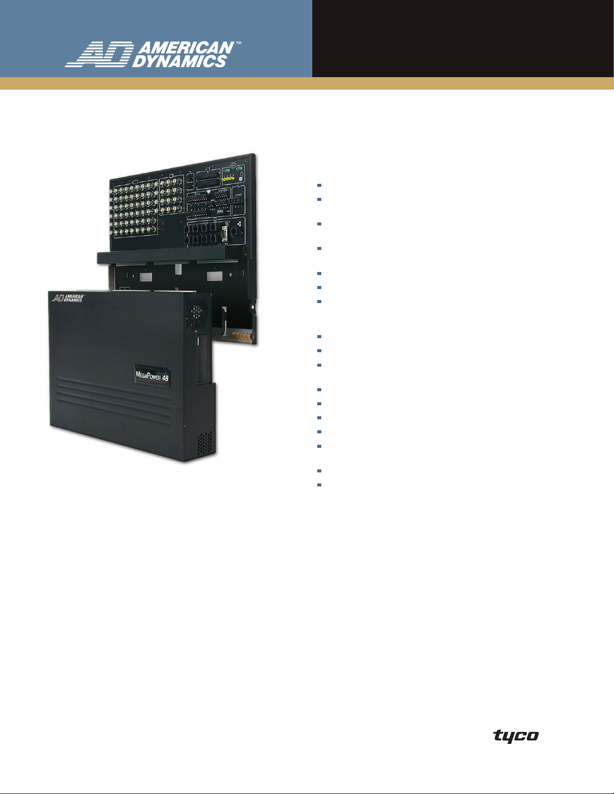
MegaPower 48 Plus
Matrix Switcher/Controller System
Features That Make a Difference:
Universal MEU supports both NTSC and PAL
3 flexible exansion modes using a primary/secondary configuration of
up to 7 systems and 288 cameras
Ethernet Cat 5 IP connection for multi-matrix communications and
system setup
EASY 48 configuration and monitoring software for Windows® XP, 2000,
95/98 and NT® 4.0-based systems
Dome ping test and status display
RS-422 dome support, including simplex RS-422
DirectSet function control menu for SensorNet or RS-422 domes with
ControlCenter 200/300 DirectSet key or ADTTE, and AD2088, and
AD2089 site keys
48 video inputs
16 video outputs, 8 with text overlay
Optional Unshielded Twisted Pair (UTP) Adaptor Module allows
installation with simple UTP cable for video
Full embedded system menus for easy setup
Recorder control
User-defined macros
4096 preset titles and 250 alarm titles
Dedicated alarm programming tables differentiate between
alarm sources
RS-232 inputs expandable to 32
64 system tours and 64 salvos
MegaPower 48 Plus is an IP-enabled matrix switcher/controller
system that can operate as a standalone system or as part of
a network. Choose from one of three expansion modes and
grow your system by up to 288 inputs. Whether used as a
centralized or distributed system, MegaPower 48 Plus can be
cost-effectively installed and optimized for the most challenging
of site requirements.
The new EASY 48 system configuration software is a
user-friendly MS Windows application that permits the
administrator to program MegaPower 48 Plus either on-site
or remotely via Ethernet or RS-232. Use it to remotely check
the system status of cameras and monitors via an Ethernet
connection or to back up and restore system data.
The slim modular wall-mount design saves space and reduces
cabling costs by letting you install MegaPower 48 Plus in
the location that is most central to your cameras. Because it
doesn’t have to be rack mounted in a control room,
MegaPower 48 Plus can be installed anywhere in your facility
– even an electrical closet, or maximize the space and fit in
more devices in your standard rack by installing it at 90°
angle behind other equipment. You can also rack mount
MegaPower 48 Plus at other angles to facilitate easy cable
connections with the optional rack mount kit.
Page 2
features
Secondary Units
Primary
8 trunk video
8 trunk video
8 trunk video
8 trunk video
8 trunk video
8 trunk video
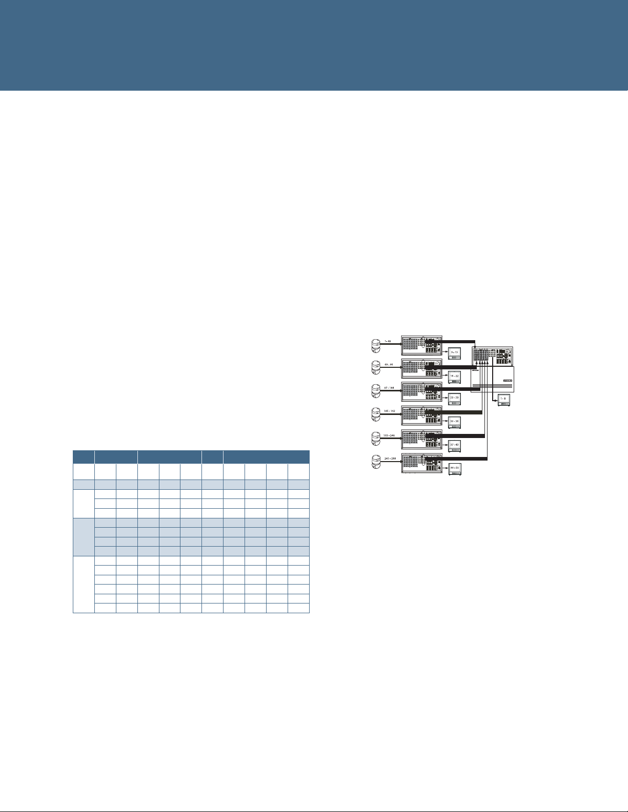
System Expansion
Systems are expanded with a primary-to-secondary
relationship. There are three modes of expansion,
using Ethernet for command and control. If inter-matrix
communication is disrupted, all secondary units continue
functioning locally and the primary provides status to users of
the fault condition.
Mode 0: Basic system, 48 video inputs, 16 full crosspoint
video outputs.
Mode 1: The primary unit has 16 video trunk lines from each
of up to three secondary units, providing 16 full
crosspoint video outputs with up to 144 video inputs.
Mode 2: The primary unit has 12 video trunk lines from each
of up to four secondary units, providing 12 full
crosspoint video outputs with up to 192 video inputs.
Each secondary has three local outputs with full
crosspoint video switching of local cameras.
Mode 3: The primary unit has eight video trunk lines from
each of up to six secondary units, providing 8 full
crosspoint video outputs with up to 288 video inputs.
Each secondary has seven local outputs with full
crosspoint video switching of local cameras.
System Programming
On-screen menus enable you to program system features
from any full-system keyboard. Operators can use the monitors
with text overlay to program the system. In addition, the
EASY 48 system configuration software enables you to
custom-configure using computers running Windows XP,
2000, 95/98 or NT 4.0. This software package provides
simplified setup, archiving and retrieval of setup as well as the
ability to load and retrieve that data via Ethernet or RS-232.
RS-232 Communications
Eight direct ports allow standard communication with
keyboards, alarm interface units, recorder control devices,
computers, third party devices, modems (for text message
paging), and more. Each port can expand to four ports with
an optional port expander.
Mode 3 Example
Expansion Mode Chart
Total
Output s
KEY-
BOARDS
Patch
Panel
Dome
ALARMS
Video
Loss
RS232
Alarms
PRIMARY SECONDARY
Mode Inputs Output s Units
0 48 16 0 N/A N/A 32 16 192 48 512
80 16 1 0 0 64 32 320 80 512
112 16 2 0 0 96 48 448 112 512
1
144 16 3 0 0 128 64 576 144 512
84 12 1 3 3 64 32 336 84 512
120 12 2 3 6 96 48 480 120 512
2
156 12 3 3 9 128 64 624 156 512
192 12 4 3 12 160 80 768 192 512
88 8 1 7 7 64 32 352 88 512
128 8 2 7 14 96 48 512 128 512
168 8 3 7 21 128 64 672 168 512
3
208 8 4 7 28 160 80 832 208 512
248 8 5 7 35 192 96 992 248 512
288 8 6 7 42 224 112 1152 2888 512
Output s
Per
Camera Site Control
Users can control domes, pan/tilts, motorized lenses, auxiliary
outputs, presets and patterns at suitably-equipped camera
sites via SensorNet, RS-422 and Manchester outputs. To
better support legacy SpeedDomes and installations that use
simplex RS-422 communication, the system allows presets to
be stored in the dome.
Selectable On-Screen Text
Each of the first eight monitors can display the date/time,
video input number, 16-character user-definable video input or
preset title, alarm title, monitor status, and secondary status.
Macro Control
The system’s powerful macros allow each operator to
customize their own ControlCenter 1100 or AD2088/AD2089
workstations to perform a multitude of tasks via simple,
intuitive, easy-to-remember keystrokes.
Recorder Control
Users can control all of the standard recorder functions directly
from any suitably-equipped keyboard – play, stop, pause,
record, rewind, fast forward, and eject.
Pseudo Camera Numbers
Users can assign a four digit number to replace the default
video input number for each video input, making it easier
to identify cameras in multiple level buildings and similar
situations.
Page 3

System and Monitor Tours
A tour is a sequence of video inputs with each input featuring
an individual dwell time, a preset/pattern and an auxiliary
action. Tours can run forward or in reverse. Video partitioned
from a monitor is skipped.
Event Timers
There are 35 user-programmable times available. These times
may be independently designated for multiple days of the
week to automatically call up system tours to video outputs.
Event timers also enable you to activate and deactivate alarm
contacts based on the time of day.
Salvo Switching
Salvo switching allows multiple video inputs to be called
simultaneously to multiple contiguous video outputs.
Sixty-four individual groups (salvos) consisting of up to
16 video inputs (each with a preset, pattern and/or auxiliary
action) can be called either manually or as part of a
system tour.
System Partitioning
System flexibility is further enhanced by defining authorized
access to keyboards, video inputs and video outputs. System
partitioning includes:
• Keyboard-to-Monitor Access: Restricts selected keyboards
from accessing selected video outputs.
• Monitor-to-Camera Access: Restricts selected video outputs
from displaying selected video inputs.
• Keyboard-to-Camera Access: Restricts selected keyboards
from calling or controlling selected video inputs.
• Keyboard-to-Camera Control Access: Allows selected
keyboards to access views from certain cameras but
restricts those keyboards from controlling the cameras.
Password and Priority Operation
Keyboards or users can be assigned one of eight priority levels
for controlling remote camera sites. Up to 64 user codes, each
with a unique password, can be assigned to operators. Access
to certain system features may be restricted depending on a
user’s priority level.
Automatic Alarm Callup
Alarm inputs can be programmed to call any video input or
salvo to any one or more video outputs. For each alarm input,
users can define a camera, preset, pattern, wireless text
message, salvo, alarm message and/or auxiliary action (with
individual dwell time for each to accommodate sequencing
alarms). In addition, two local patch panel relays can be
triggered upon any alarm event. Any combination of 25 alarm
display/clearance methods may be selected independently for
each video output. Alarms can hold or sequence on outputs.
Blocks of monitors can be defined; normal, automatic and
instant clearing are supported.
Internal Video Loss Detection
Video loss detection is standard on all video inputs. Upon
video loss, a system alarm is generated. Enabling video loss
detection occupies video output 16.
Text Message Paging on Alarm
MegaPower 48 Plus can transmit text messages to cellular
phones and pagers when an alarm occurs, alerting users with
a detailed description of the event and instructions for how to
respond. With alarm programming, a single event can trigger
multiple unique messages to one or more recipients. You can
program as many as 64 different pager profiles and define
up to 250 unique text messages for transmitting. The paging
feature supports the TAP protocol via an external modem
(not supplied).
Diagnostics and Dome Information
Screens
Built-in diagnostics clearly indicate power status and system
health, allowing you to determine the status of the system’s
internal components. The dome information screen shows the
video detection status, dome mnemonic, dome protocol,
dome software version and whether the dome is responding
to the system polls for each camera on the system.
For troubleshooting purposes, the dome ping test screen
allows the installer to verify the integrity of SensorNet and
RS-422 communications and display dome firmware
number, mnemonic, serial number and production date.
Flash Memory Module for Data Backup
The system is comprised of a passive patch panel for all
system wiring and a removable main electronics unit (MEU).
There is also a flash memory module that is separate from the
MEU and lets you automatically back up data without a PC.
This allows you to replace a system and restore the existing
data in less than one minute.
Digital Video Management
System Control
The AD2089 keyboard allows you to control Intellex digital
video management systems including playback of archived
video. This feature requires Intellex and Network Client v4.04.
Status Output
System status output via an RS-232 printer port may be
programmed to output both the occurrence and clearing of
all alarms as well as power status and monitor messages.
Page 4

S P E C I F I C A T I O N S
Model Numbers
Each MegaPower 48 Plus system consists of a wall-mount assembly (bracket
and patch panel assembly), main electronics unit (Universal, NTSC or PAL),
pre-wired transformer assembly (selectable voltage), and documentation kit
including CD with various languages.
ADMP48–E . . . . . . . . . . . . . . MegaPower 48 Plus, Universal
Optional Accessories
Keyboards
ADCC1100 - MegaPower 1100 keyboard
with smart card and macro keys
ADTTE - Touch Tracker keyboard
ADCC0200P - ControlCenter 200 keyboard
with 2-axis joystick
ADCC0300P - ControlCenter 300 keyboard
with joystick and programming access
AD2089 - Full system keyboard
with macro keys and video recorder control (DVR or VCR)
Other Accessories
AD2081, AD2081-1 Port Expander
Expands one RS-232 port on a system into four ports, providing
connections to multiple system keyboards.
AD2096A, AD2096-1 Alarm Interface
Monitors up to 64 alarm inputs and provides RS-232 ASCII alarm
commands to the system. Up to eight units can be cascaded on a
RS-232 line.
AD2031, AD2031-1 Switcher Follower
Activates relays when designated video inputs are called to designated video
outputs. It interfaces via Manchester and provides up to 32 Form A relays that
can be grouped in series and addressed to a single video output or in two
groups of 16 relays for two specific video outputs.
AD2032, AD2032-1 Alarm Responder
Activates relays when associated video outputs are in an alarmed condition.
Interfaces via Manchester and provides up to 32 Form A relays.
AD2033, AD2033-1 Auxiliary Follower
Activates relays when a specific auxiliary is triggered either manually or
automatically for an associated video input. Interfaces with matrix switcher/
controllers and provides up to 32 Form A relays via Manchester. Multiple units
can be cascaded together.
VR48RKIT Rack Mount Kit
This enables the MegaPower 48 Plus system to be rack mounted in a
standard 19-inch EIA rack mount.
ADACTP01BNC · Unshielded Twisted Pair Adaptor Module
This allows installation with simple UTP cable for video lines.
VRCMKIT Cable Brackets
Each kit contains three additional cable management brackets.
Operational
Bandwidth . . . . . . . . . . . . . . .10 MHz
Frequency Response . . . . . . .± 1.0 dB to 6 MHz
S/N Ratio . . . . . . . . . . . . . . . .60 dB (Vp-p vs. Vrms noise)
Crosstalk
Adjacent Channels . . . . . . . . ≤ -55 dB (at 3.58 MHz)
Input to Input . . . . . . . . . . . .≤-70 dB (at 3.58 MHz)
Differential Delay . . . . . . . . .± 1.0°
Differential Phase . . . . . . . . . ≤ 0.5°
Differential Gain . . . . . . . . . .≤1.5%
Tilt . . . . . . . . . . . . . . . . . . . . ≤ 2.0%
Gain . . . . . . . . . . . . . . . . . . .Unity ± 1 dB
Return Loss
Input/Output . . . . . . . . . . . .40 dB
DC Level (Video Signal) . . . . 0 Volts (± 0.1 V typical)
Switching . . . . . . . . . . . . . . . Complete switching of crosspoint matrix
EIA RS-170 and NTSC, CCIR and PAL
Switching Speed . . . . . . . . . . Less than 20 ms (typical)
On-Screen Text . . . . . . . . . . .Date/time, video input number, video
Outputs 1-8 . . . . . . . . . . . . . . Input or preset title (16 characters), monitor
status, alarm title (48 characters)
Character Set . . . . . . . . . . . . . . English, French, Italian, German, Spanish,
Portuguese
Video Inputs . . . . . . . . . . . . . . 48 BNC composite, 0.5 to 2.0 Vp-p
Video Outputs . . . . . . . . . . . . 16 BNC composite, 1.0 Vp-p (with nominal input)
RS-232 . . . . . . . . . . . . . . . . . Eight 8-pin RJ-45 optional port expander
extends each port to four
Network . . . . . . . . . . . . . . . . . Ethernet, IEEE 802.3, 10 Mbps, TCP/IP
Utilization . . . . . . . . . . . . . . . .< 2.5%
Connection . . . . . . . . . . . . . .RJ-45, Cat 5 wiring
Protocol . . . . . . . . . . . . . . . . . IP, fixed addresses, supports gateway
connection
External Modem . . . . . . . . . . One DB9 connector (Hayes AT compatible)
SensorNet . . . . . . . . . . . . . . . Six ports through terminal screw connectors
SEC RS-422 . . . . . . . . . . . . . Six ports through terminal screw connectors
Manchester . . . . . . . . . . . . . . One port through terminal screw connectors
Alarm Inputs. . . . . . . . . . . . . . 16 inputs through two 16-pin terminal
screw connectors
Relay Outputs . . . . . . . . . . . . Two Form-C relays through two 3-pin terminal
screw connectors
Power. . . . . . . . . . . . . . . . . . . One 3-pin terminal screw connector
Flash Memory Module . . . . . .One 8-pin header
Electrical
Power Source . . . . . . . . . . . .12 VDC external power supply, universal
Supply Voltage . . . . . . . . . . . . 100-240 VAC, 50-60 Hz
Power Requirements . . . . . . ..5 amps, 42 VA
Mechanical
Mounting . . . . . . . . . . . . . . . .Vertical wall or 19-inch EIA rack mount
Dimensions (H x W x D) . . . . . 50.8 x 43.8 x 8.9 cm (20 x 17.3 x 3.5 in)
Unit Weight
Wall Bracket . . . . . . . . . . . . . 1.54 kg (3.4 lbs)
Patch Panel Assembly . . . . .1.72 kg (3.8 lbs)
Main Electronics Unit . . . . . . 2.72 kg (6.0 lbs)
Total Weight . . . . . . . . . . . . .5.97 kg (13.2 lbs)
Transformer Weight . . . . . . .2.17 kg (4.8 lbs)
Color . . . . . . . . . . . . . . . . . . . Black
Environmental
Operating Temperature . . . . .0° to 50° C (32° to 122° F)
Humidity . . . . . . . . . . . . . . . .5 to 95% RH (non-condensing)
Storage Temperature . . . . . . .-40° to 70° C (-40° to 155° F)
Regulatory
Emissions . . . . . . . . . . . . . . . FCC Part 15, Class A
EN55022 (CE)
Immunity . . . . . . . . . . . . . . . .EN50130-4 (CE)
Safety . . . . . . . . . . . . . . . . . . . UL1950
CSA 22.2, No. 950
(cUL) EN60950 (CE)
EASY 48
PC Recommendation . . . . . . Windows XP, 2000, NT 4.0 or 95/98
800 MHz Processor
1 GB hard disk space
256 MB RAM
Product offerings and specifications are subject to change without notice. Actual products may vary from photos. Not all products include all features. Availability varies by
region; contact your sales representative. Certain product names mentioned herein may be trade names and/or registered trademarks of other companies.
© 2008 Tyco International, Ltd. and its Respective Companies. All Rights Reserved. AD0120-DS-200801-R01-LT-EN
www.americandynamics.net
 Loading...