

American Dynamics ADCI625-P121, ADCI625-P122, ADCI625-P123, ADCI625-P124, ADCI625-P132 Quick User Guide
...Page 1

Configuration and User
Guide
Illustra 625 PTZ Camera
8200-0999-06 B0
Page 2

Notice
The information in this manual was current when published. The manufacturer reserves the right to revise and improve its
products. All specifications are therefore subject to change without notice.
Copyright
Under copyright laws, the contents of this manual may not be copied, photocopied, reproduced, translated or reduced to
any electronic medium or machine-readable form, in whole or in part, without prior written consent of Tyco Security
Products. © 2013 Tyco Security Products. All rights reserved.
American Dynamics
6600 Congress Avenue
Boca Raton, FL 33487 U.S.A.
Customer Service
Thank you for using American Dynamics products. We support our products through an extensive worldwide network of
dealers. The dealer through whom you originally purchased this product is your point of contact if you need service or
support. Our dealers are empowered to provide the very best in customer service and support. Dealers should contact
American Dynamics at (800) 507-6268 or (561) 912-6259 or on the Web at www.americandynamics.net.
Trademarks
Windows® is a registered trademark of Microsoft Corporation. PS/2® is a registered trademark of International Business
Machines Corporation.
The trademarks, logos, and service marks displayed on this document are registered in the United States [or other
countries]. Any misuse of the trademarks is strictly prohibited and Tyco Security Products. will aggressively enforce its
intellectual property rights to the fullest extent of the law, including pursuit of criminal prosecution wherever necessary. All
trademarks not owned by Tyco Security Products. are the property of their respective owners, and are used with
permission or allowed under applicable laws.
Product offerings and specifications are subject to change without notice. Actual products may vary from photos. Not all
products include all features. Availability varies by region; contact your sales representative.
License Information
Your use of this product is governed by certain terms and conditions. Please see the detailed license information at the end
of this manual.
i-ii Configuration and User Guide
Page 3

Table of Contents
Introduction 1
Overview . . . . . . . . . . . . . . . . . . . . . . . . . . . . . . . . . . . . . . . . . . . . . . . . . . . . . . . . . . . . . . . . . .1
Installation 3
Camera Mounts. . . . . . . . . . . . . . . . . . . . . . . . . . . . . . . . . . . . . . . . . . . . . . . . . . . . . . . . . . . . .3
Network Settings . . . . . . . . . . . . . . . . . . . . . . . . . . . . . . . . . . . . . . . . . . . . . . . . . . . . . . . . . . . .3
Installation Process . . . . . . . . . . . . . . . . . . . . . . . . . . . . . . . . . . . . . . . . . . . . . . . . . . . . . . . . . . 4
Illustra Connect . . . . . . . . . . . . . . . . . . . . . . . . . . . . . . . . . . . . . . . . . . . . . . . . . . . . . . . . . . . . .5
Install and Detect the Illustra 625 PTZ Dome . . . . . . . . . . . . . . . . . . . . . . . . . . . . . . . . . . . . . . 6
Installation using DHCP and Illustra Connect . . . . . . . . . . . . . . . . . . . . . . . . . . . . . . . . . . . 6
Installing the Illustra 625 PTZ Camerausing DHCP Server Logs. . . . . . . . . . . . . . . . . . . . . 7
Installation without a DHCP Server using a Static IP Address . . . . . . . . . . . . . . . . . . . . . 7
Web Configuration 9
Log in and Log Off the Dome . . . . . . . . . . . . . . . . . . . . . . . . . . . . . . . . . . . . . . . . . . . . . . . . . 10
Logging in to the Dome . . . . . . . . . . . . . . . . . . . . . . . . . . . . . . . . . . . . . . . . . . . . . . . . . . . 10
Logging out of the Dome . . . . . . . . . . . . . . . . . . . . . . . . . . . . . . . . . . . . . . . . . . . . . . . . . . 10
User Accounts. . . . . . . . . . . . . . . . . . . . . . . . . . . . . . . . . . . . . . . . . . . . . . . . . . . . . . . . . . . . . 11
Administrator Access . . . . . . . . . . . . . . . . . . . . . . . . . . . . . . . . . . . . . . . . . . . . . . . . . . . . . 11
Operator Access. . . . . . . . . . . . . . . . . . . . . . . . . . . . . . . . . . . . . . . . . . . . . . . . . . . . . . . . .11
User Access . . . . . . . . . . . . . . . . . . . . . . . . . . . . . . . . . . . . . . . . . . . . . . . . . . . . . . . . . . . .11
The Dome Web GUI Interface. . . . . . . . . . . . . . . . . . . . . . . . . . . . . . . . . . . . . . . . . . . . . . . . .11
Accessing the Setup Menus from Full Screen Live View. . . . . . . . . . . . . . . . . . . . . . . . . . 12
Displaying Full Screen Live Video . . . . . . . . . . . . . . . . . . . . . . . . . . . . . . . . . . . . . . . . . . .12
Overview of the Web GUI . . . . . . . . . . . . . . . . . . . . . . . . . . . . . . . . . . . . . . . . . . . . . . . . . . . .13
GUI Icons . . . . . . . . . . . . . . . . . . . . . . . . . . . . . . . . . . . . . . . . . . . . . . . . . . . . . . . . . . . . . . . . 14
Viewing Live Video via the Live Video Pane . . . . . . . . . . . . . . . . . . . . . . . . . . . . . . . . . . . . . .14
Viewing Live Video via the Live Video Pane . . . . . . . . . . . . . . . . . . . . . . . . . . . . . . . . . . . 14
ii-i
Page 4

Table of Contents
Controlling the Dome using Camera Controls. . . . . . . . . . . . . . . . . . . . . . . . . . . . . . . . . . . . .15
GUI Camera Controls. . . . . . . . . . . . . . . . . . . . . . . . . . . . . . . . . . . . . . . . . . . . . . . . . . . . . 15
Controlling the camera via Keyboard Shortcuts . . . . . . . . . . . . . . . . . . . . . . . . . . . . . . . . .16
Controlling the camera via Camera Controls . . . . . . . . . . . . . . . . . . . . . . . . . . . . . . . . . . . 16
Controlling the Pan/Tilt Control via Click and Drag . . . . . . . . . . . . . . . . . . . . . . . . . . . . . . 16
Zooming Using the Mouse Scroll Wheel . . . . . . . . . . . . . . . . . . . . . . . . . . . . . . . . . . . . . . 17
Double-click to Center using the mouse. . . . . . . . . . . . . . . . . . . . . . . . . . . . . . . . . . . . . . . 17
PTZ to a Selected Area using the mouse. . . . . . . . . . . . . . . . . . . . . . . . . . . . . . . . . . . . . . 18
View Menu 19
White Balance . . . . . . . . . . . . . . . . . . . . . . . . . . . . . . . . . . . . . . . . . . . . . . . . . . . . . . . . . . . . . 20
Configuring White Balance. . . . . . . . . . . . . . . . . . . . . . . . . . . . . . . . . . . . . . . . . . . . . . . . . 20
Configuring the Red and Blue Balance . . . . . . . . . . . . . . . . . . . . . . . . . . . . . . . . . . . . . . .20
Picture Balance . . . . . . . . . . . . . . . . . . . . . . . . . . . . . . . . . . . . . . . . . . . . . . . . . . . . . . . . . . . .21
Adjusting Picture Balance . . . . . . . . . . . . . . . . . . . . . . . . . . . . . . . . . . . . . . . . . . . . . . . . . 21
Restoring Picture Balance . . . . . . . . . . . . . . . . . . . . . . . . . . . . . . . . . . . . . . . . . . . . . . . . . 21
Focus/Iris. . . . . . . . . . . . . . . . . . . . . . . . . . . . . . . . . . . . . . . . . . . . . . . . . . . . . . . . . . . . . . . . .22
Setting Auto Focus . . . . . . . . . . . . . . . . . . . . . . . . . . . . . . . . . . . . . . . . . . . . . . . . . . . . . . . 22
Setting Auto Iris . . . . . . . . . . . . . . . . . . . . . . . . . . . . . . . . . . . . . . . . . . . . . . . . . . . . . . . . . 23
Wide Dynamic Range . . . . . . . . . . . . . . . . . . . . . . . . . . . . . . . . . . . . . . . . . . . . . . . . . . . . . . .23
Configuring WDR . . . . . . . . . . . . . . . . . . . . . . . . . . . . . . . . . . . . . . . . . . . . . . . . . . . . . . . . 23
IR/DayNight Mode. . . . . . . . . . . . . . . . . . . . . . . . . . . . . . . . . . . . . . . . . . . . . . . . . . . . . . . . . .24
IR Mode . . . . . . . . . . . . . . . . . . . . . . . . . . . . . . . . . . . . . . . . . . . . . . . . . . . . . . . . . . . . . . .24
Configuring IR . . . . . . . . . . . . . . . . . . . . . . . . . . . . . . . . . . . . . . . . . . . . . . . . . . . . . . . . . . 24
Day Night Mode . . . . . . . . . . . . . . . . . . . . . . . . . . . . . . . . . . . . . . . . . . . . . . . . . . . . . . . . .25
Configuring Day Night Mode . . . . . . . . . . . . . . . . . . . . . . . . . . . . . . . . . . . . . . . . . . . . . . . 25
Shutter Limit . . . . . . . . . . . . . . . . . . . . . . . . . . . . . . . . . . . . . . . . . . . . . . . . . . . . . . . . . . . . . .25
Automatic Gain Control (AGC) . . . . . . . . . . . . . . . . . . . . . . . . . . . . . . . . . . . . . . . . . . . . 26
Open Shutter. . . . . . . . . . . . . . . . . . . . . . . . . . . . . . . . . . . . . . . . . . . . . . . . . . . . . . . . . .26
Configuring AGC/Shutter Settings . . . . . . . . . . . . . . . . . . . . . . . . . . . . . . . . . . . . . . . . . . . 26
Shutter Speed . . . . . . . . . . . . . . . . . . . . . . . . . . . . . . . . . . . . . . . . . . . . . . . . . . . . . . . . . . . . .27
Changing the Shutter Speed . . . . . . . . . . . . . . . . . . . . . . . . . . . . . . . . . . . . . . . . . . . . . . .27
Max Gain. . . . . . . . . . . . . . . . . . . . . . . . . . . . . . . . . . . . . . . . . . . . . . . . . . . . . . . . . . . . . . . . .27
Configuring Max Gain. . . . . . . . . . . . . . . . . . . . . . . . . . . . . . . . . . . . . . . . . . . . . . . . . . . . . 27
Picture Settings . . . . . . . . . . . . . . . . . . . . . . . . . . . . . . . . . . . . . . . . . . . . . . . . . . . . . . . . . . . .28
Saving Picture Settings . . . . . . . . . . . . . . . . . . . . . . . . . . . . . . . . . . . . . . . . . . . . . . . . . . . 28
Restoring Saved Picture Settings. . . . . . . . . . . . . . . . . . . . . . . . . . . . . . . . . . . . . . . . . . . . 29
Restoring Factory Default Picture Settings . . . . . . . . . . . . . . . . . . . . . . . . . . . . . . . . . . . . 29
Presets . . . . . . . . . . . . . . . . . . . . . . . . . . . . . . . . . . . . . . . . . . . . . . . . . . . . . . . . . . . . . . . . . . 30
Adding a new Preset . . . . . . . . . . . . . . . . . . . . . . . . . . . . . . . . . . . . . . . . . . . . . . . . . . . . . 30
Viewing a Preset . . . . . . . . . . . . . . . . . . . . . . . . . . . . . . . . . . . . . . . . . . . . . . . . . . . . . . . .30
Editing a Preset . . . . . . . . . . . . . . . . . . . . . . . . . . . . . . . . . . . . . . . . . . . . . . . . . . . . . . . . . 31
Deleting a Preset . . . . . . . . . . . . . . . . . . . . . . . . . . . . . . . . . . . . . . . . . . . . . . . . . . . . . . . .32
ii-ii Configuration and User Guide
Page 5

Table of Contents
Patterns. . . . . . . . . . . . . . . . . . . . . . . . . . . . . . . . . . . . . . . . . . . . . . . . . . . . . . . . . . . . . . . . . . 33
Adding a Pattern. . . . . . . . . . . . . . . . . . . . . . . . . . . . . . . . . . . . . . . . . . . . . . . . . . . . . . . . .33
Running a Pattern . . . . . . . . . . . . . . . . . . . . . . . . . . . . . . . . . . . . . . . . . . . . . . . . . . . . . . . 34
Deleting a Pattern. . . . . . . . . . . . . . . . . . . . . . . . . . . . . . . . . . . . . . . . . . . . . . . . . . . . . . . .34
Repeating a Pattern . . . . . . . . . . . . . . . . . . . . . . . . . . . . . . . . . . . . . . . . . . . . . . . . . . . . . .35
Privacy Zones . . . . . . . . . . . . . . . . . . . . . . . . . . . . . . . . . . . . . . . . . . . . . . . . . . . . . . . . . . . . . 36
Defining a Privacy Zone . . . . . . . . . . . . . . . . . . . . . . . . . . . . . . . . . . . . . . . . . . . . . . . . . . . 36
Enabling or Disabling a Privacy Zone . . . . . . . . . . . . . . . . . . . . . . . . . . . . . . . . . . . . . . . . 37
Deleting a Privacy Zone . . . . . . . . . . . . . . . . . . . . . . . . . . . . . . . . . . . . . . . . . . . . . . . . . . . 37
Scans . . . . . . . . . . . . . . . . . . . . . . . . . . . . . . . . . . . . . . . . . . . . . . . . . . . . . . . . . . . . . . . . . . . 39
Setting Scan Limits. . . . . . . . . . . . . . . . . . . . . . . . . . . . . . . . . . . . . . . . . . . . . . . . . . . . . . .39
Set Scan Limits to Default Settings . . . . . . . . . . . . . . . . . . . . . . . . . . . . . . . . . . . . . . . . . . 39
Activating a Scan . . . . . . . . . . . . . . . . . . . . . . . . . . . . . . . . . . . . . . . . . . . . . . . . . . . . . . . .40
Programs Menu 41
Sequences . . . . . . . . . . . . . . . . . . . . . . . . . . . . . . . . . . . . . . . . . . . . . . . . . . . . . . . . . . . . . . . 42
Adding a Sequence . . . . . . . . . . . . . . . . . . . . . . . . . . . . . . . . . . . . . . . . . . . . . . . . . . . . . . 42
Activating a Sequence . . . . . . . . . . . . . . . . . . . . . . . . . . . . . . . . . . . . . . . . . . . . . . . . . . . . 42
Editing a Sequence . . . . . . . . . . . . . . . . . . . . . . . . . . . . . . . . . . . . . . . . . . . . . . . . . . . . . . 43
Deleting a Sequence . . . . . . . . . . . . . . . . . . . . . . . . . . . . . . . . . . . . . . . . . . . . . . . . . . . . . 44
Alarms. . . . . . . . . . . . . . . . . . . . . . . . . . . . . . . . . . . . . . . . . . . . . . . . . . . . . . . . . . . . . . . . . . . 45
Alarm Actions . . . . . . . . . . . . . . . . . . . . . . . . . . . . . . . . . . . . . . . . . . . . . . . . . . . . . . . . .45
Creating an Alarm . . . . . . . . . . . . . . . . . . . . . . . . . . . . . . . . . . . . . . . . . . . . . . . . . . . . . . . 46
Enabling or Disabling an Alarm . . . . . . . . . . . . . . . . . . . . . . . . . . . . . . . . . . . . . . . . . . . . .47
Enable or Disable Alarm Output. . . . . . . . . . . . . . . . . . . . . . . . . . . . . . . . . . . . . . . . . . . . . 48
Editing an Alarm . . . . . . . . . . . . . . . . . . . . . . . . . . . . . . . . . . . . . . . . . . . . . . . . . . . . . . . . .48
View Active Alarms. . . . . . . . . . . . . . . . . . . . . . . . . . . . . . . . . . . . . . . . . . . . . . . . . . . . . . . 48
Clearing Alarm Output Logs . . . . . . . . . . . . . . . . . . . . . . . . . . . . . . . . . . . . . . . . . . . . . . . . 49
MicroSD Card. . . . . . . . . . . . . . . . . . . . . . . . . . . . . . . . . . . . . . . . . . . . . . . . . . . . . . . . . . .49
Inserting the MicroSD Card . . . . . . . . . . . . . . . . . . . . . . . . . . . . . . . . . . . . . . . . . . . . . . . . 50
Removing the MicroSD Card . . . . . . . . . . . . . . . . . . . . . . . . . . . . . . . . . . . . . . . . . . . . . . . 50
Scheduled Tasks. . . . . . . . . . . . . . . . . . . . . . . . . . . . . . . . . . . . . . . . . . . . . . . . . . . . . . . . . . . 53
Creating a Scheduled Task . . . . . . . . . . . . . . . . . . . . . . . . . . . . . . . . . . . . . . . . . . . . . . . . 53
Editing a Scheduled Task. . . . . . . . . . . . . . . . . . . . . . . . . . . . . . . . . . . . . . . . . . . . . . . . . . 54
Deleting a Scheduled Task . . . . . . . . . . . . . . . . . . . . . . . . . . . . . . . . . . . . . . . . . . . . . . . . 54
Areas. . . . . . . . . . . . . . . . . . . . . . . . . . . . . . . . . . . . . . . . . . . . . . . . . . . . . . . . . . . . . . . . . . . .56
Programming an Area . . . . . . . . . . . . . . . . . . . . . . . . . . . . . . . . . . . . . . . . . . . . . . . . . . . . 56
Editing an Area. . . . . . . . . . . . . . . . . . . . . . . . . . . . . . . . . . . . . . . . . . . . . . . . . . . . . . . . . . 56
Deleting an Area. . . . . . . . . . . . . . . . . . . . . . . . . . . . . . . . . . . . . . . . . . . . . . . . . . . . . . . . .57
ii-iii
Page 6

Table of Contents
Camera Configuration Menu 59
PTZ . . . . . . . . . . . . . . . . . . . . . . . . . . . . . . . . . . . . . . . . . . . . . . . . . . . . . . . . . . . . . . . . . . . . . 60
Adjusting Automatic Flip. . . . . . . . . . . . . . . . . . . . . . . . . . . . . . . . . . . . . . . . . . . . . . . . . . . 60
Freeze Frame. . . . . . . . . . . . . . . . . . . . . . . . . . . . . . . . . . . . . . . . . . . . . . . . . . . . . . . . . . .60
Return Settings. . . . . . . . . . . . . . . . . . . . . . . . . . . . . . . . . . . . . . . . . . . . . . . . . . . . . . . . . . 61
North Position. . . . . . . . . . . . . . . . . . . . . . . . . . . . . . . . . . . . . . . . . . . . . . . . . . . . . . . . . . .61
On-Screen Display (OSD). . . . . . . . . . . . . . . . . . . . . . . . . . . . . . . . . . . . . . . . . . . . . . . . . . . . 63
Displaying the Camera Name . . . . . . . . . . . . . . . . . . . . . . . . . . . . . . . . . . . . . . . . . . . . . . 63
Displaying Camera Status . . . . . . . . . . . . . . . . . . . . . . . . . . . . . . . . . . . . . . . . . . . . . . . . . 63
Displaying Dome Names . . . . . . . . . . . . . . . . . . . . . . . . . . . . . . . . . . . . . . . . . . . . . . . . . . 64
Displaying Time/Direction Indicators . . . . . . . . . . . . . . . . . . . . . . . . . . . . . . . . . . . . . . . . .64
Configuring Text Attributes. . . . . . . . . . . . . . . . . . . . . . . . . . . . . . . . . . . . . . . . . . . . . . . . . 65
Video . . . . . . . . . . . . . . . . . . . . . . . . . . . . . . . . . . . . . . . . . . . . . . . . . . . . . . . . . . . . . . . . . . . . 66
Web GUI Video . . . . . . . . . . . . . . . . . . . . . . . . . . . . . . . . . . . . . . . . . . . . . . . . . . . . . . . . 66
Alarm Video . . . . . . . . . . . . . . . . . . . . . . . . . . . . . . . . . . . . . . . . . . . . . . . . . . . . . . . . . . 66
Integration with American Dynamics Network Video Recorders. . . . . . . . . . . . . . . . . . .66
Integration with other Illustra API Clients . . . . . . . . . . . . . . . . . . . . . . . . . . . . . . . . . . . . 66
MJPEG Usage Consideration . . . . . . . . . . . . . . . . . . . . . . . . . . . . . . . . . . . . . . . . . . . . . 66
Configuring the Web Video Stream . . . . . . . . . . . . . . . . . . . . . . . . . . . . . . . . . . . . . . . . . . 67
Select the Alarm Video Stream . . . . . . . . . . . . . . . . . . . . . . . . . . . . . . . . . . . . . . . . . . . . . 68
Audio . . . . . . . . . . . . . . . . . . . . . . . . . . . . . . . . . . . . . . . . . . . . . . . . . . . . . . . . . . . . . . . . . . . . 70
Configuring Audio Input . . . . . . . . . . . . . . . . . . . . . . . . . . . . . . . . . . . . . . . . . . . . . . . . . . . 70
Configuring Audio Output . . . . . . . . . . . . . . . . . . . . . . . . . . . . . . . . . . . . . . . . . . . . . . . . . . 70
Configuring Stored Audio . . . . . . . . . . . . . . . . . . . . . . . . . . . . . . . . . . . . . . . . . . . . . . . . . . 71
Uploading a Audio File . . . . . . . . . . . . . . . . . . . . . . . . . . . . . . . . . . . . . . . . . . . . . . . . . . . . 71
Deleting a Stored Audio file . . . . . . . . . . . . . . . . . . . . . . . . . . . . . . . . . . . . . . . . . . . . . . . . 72
Home. . . . . . . . . . . . . . . . . . . . . . . . . . . . . . . . . . . . . . . . . . . . . . . . . . . . . . . . . . . . . . . . . . . . 74
Setting a Home Position. . . . . . . . . . . . . . . . . . . . . . . . . . . . . . . . . . . . . . . . . . . . . . . . . . . 74
Removing the Home Position. . . . . . . . . . . . . . . . . . . . . . . . . . . . . . . . . . . . . . . . . . . . . . . 74
Networking Menu 75
TCP/IP. . . . . . . . . . . . . . . . . . . . . . . . . . . . . . . . . . . . . . . . . . . . . . . . . . . . . . . . . . . . . . . . . . . 76
IPv4 . . . . . . . . . . . . . . . . . . . . . . . . . . . . . . . . . . . . . . . . . . . . . . . . . . . . . . . . . . . . . . . . . .76
IPv6 . . . . . . . . . . . . . . . . . . . . . . . . . . . . . . . . . . . . . . . . . . . . . . . . . . . . . . . . . . . . . . . . . .76
Date Time . . . . . . . . . . . . . . . . . . . . . . . . . . . . . . . . . . . . . . . . . . . . . . . . . . . . . . . . . . . . . . . . 78
Setting Date Time. . . . . . . . . . . . . . . . . . . . . . . . . . . . . . . . . . . . . . . . . . . . . . . . . . . . . . . .78
Users. . . . . . . . . . . . . . . . . . . . . . . . . . . . . . . . . . . . . . . . . . . . . . . . . . . . . . . . . . . . . . . . . . . . 79
Add User . . . . . . . . . . . . . . . . . . . . . . . . . . . . . . . . . . . . . . . . . . . . . . . . . . . . . . . . . . . . . . 79
Changing the User Accounts Password. . . . . . . . . . . . . . . . . . . . . . . . . . . . . . . . . . . . . . . 79
Delete a User Account . . . . . . . . . . . . . . . . . . . . . . . . . . . . . . . . . . . . . . . . . . . . . . . . . . . . 80
SMTP . . . . . . . . . . . . . . . . . . . . . . . . . . . . . . . . . . . . . . . . . . . . . . . . . . . . . . . . . . . . . . . . . . . 81
Configure SMTP. . . . . . . . . . . . . . . . . . . . . . . . . . . . . . . . . . . . . . . . . . . . . . . . . . . . . . . . . 81
Test SMTP Settings . . . . . . . . . . . . . . . . . . . . . . . . . . . . . . . . . . . . . . . . . . . . . . . . . . . . . . 81
ii-iv Configuration and User Guide
Page 7

Table of Contents
FTP . . . . . . . . . . . . . . . . . . . . . . . . . . . . . . . . . . . . . . . . . . . . . . . . . . . . . . . . . . . . . . . . . . . . . 83
Configuring FTP Server Settings . . . . . . . . . . . . . . . . . . . . . . . . . . . . . . . . . . . . . . . . . . . . 83
Test FTP Settings. . . . . . . . . . . . . . . . . . . . . . . . . . . . . . . . . . . . . . . . . . . . . . . . . . . . . . . .83
Firewall . . . . . . . . . . . . . . . . . . . . . . . . . . . . . . . . . . . . . . . . . . . . . . . . . . . . . . . . . . . . . . . . . .85
Basic Filtering. . . . . . . . . . . . . . . . . . . . . . . . . . . . . . . . . . . . . . . . . . . . . . . . . . . . . . . . . . . 85
Address Filtering . . . . . . . . . . . . . . . . . . . . . . . . . . . . . . . . . . . . . . . . . . . . . . . . . . . . . . . .85
Editing an Address Filter . . . . . . . . . . . . . . . . . . . . . . . . . . . . . . . . . . . . . . . . . . . . . . . . . . 86
Deleting an Address Filter . . . . . . . . . . . . . . . . . . . . . . . . . . . . . . . . . . . . . . . . . . . . . . . . . 86
Maintenance . . . . . . . . . . . . . . . . . . . . . . . . . . . . . . . . . . . . . . . . . . . . . . . . . . . . . . . . . . . . . . 88
Backup/Restore . . . . . . . . . . . . . . . . . . . . . . . . . . . . . . . . . . . . . . . . . . . . . . . . . . . . . . . . .88
Save Camera Data. . . . . . . . . . . . . . . . . . . . . . . . . . . . . . . . . . . . . . . . . . . . . . . . . . . . . . . 88
Restore Camera Data . . . . . . . . . . . . . . . . . . . . . . . . . . . . . . . . . . . . . . . . . . . . . . . . . . . .88
Upgrade Camera Firmware . . . . . . . . . . . . . . . . . . . . . . . . . . . . . . . . . . . . . . . . . . . . . . . . 89
Upload a HTTPS Certificate . . . . . . . . . . . . . . . . . . . . . . . . . . . . . . . . . . . . . . . . . . . . . . . . 90
Delete a HTTPS Certificate . . . . . . . . . . . . . . . . . . . . . . . . . . . . . . . . . . . . . . . . . . . . . . . . 90
Rebooting the Dome . . . . . . . . . . . . . . . . . . . . . . . . . . . . . . . . . . . . . . . . . . . . . . . . . . . . . 91
Reset the Dome to Factory Default Settings . . . . . . . . . . . . . . . . . . . . . . . . . . . . . . . . . . . 92
Physical Reboot/Reset of the Dome . . . . . . . . . . . . . . . . . . . . . . . . . . . . . . . . . . . . . . . . . . . . 93
Rebooting the Dome using the Reboot/Reset Switch . . . . . . . . . . . . . . . . . . . . . . . . . . . . 93
Resetting the Dome to Factory Default Settings using the Reset/Reboot Switch . . . . . . .94
Advanced Settings . . . . . . . . . . . . . . . . . . . . . . . . . . . . . . . . . . . . . . . . . . . . . . . . . . . . . . . . . 95
Camera Name . . . . . . . . . . . . . . . . . . . . . . . . . . . . . . . . . . . . . . . . . . . . . . . . . . . . . . . . . . 95
Session Timeout. . . . . . . . . . . . . . . . . . . . . . . . . . . . . . . . . . . . . . . . . . . . . . . . . . . . . . . . .95
Remote Access . . . . . . . . . . . . . . . . . . . . . . . . . . . . . . . . . . . . . . . . . . . . . . . . . . . . . . . . . 96
SSH Enable . . . . . . . . . . . . . . . . . . . . . . . . . . . . . . . . . . . . . . . . . . . . . . . . . . . . . . . . . . 96
ONVIF . . . . . . . . . . . . . . . . . . . . . . . . . . . . . . . . . . . . . . . . . . . . . . . . . . . . . . . . . . . . . . .96
ONVIF Discovery Mode . . . . . . . . . . . . . . . . . . . . . . . . . . . . . . . . . . . . . . . . . . . . . . . . . 96
ONVIF User Authentication. . . . . . . . . . . . . . . . . . . . . . . . . . . . . . . . . . . . . . . . . . . . . . . 97
Dynamic DNS. . . . . . . . . . . . . . . . . . . . . . . . . . . . . . . . . . . . . . . . . . . . . . . . . . . . . . . . . . .97
Information 99
Model . . . . . . . . . . . . . . . . . . . . . . . . . . . . . . . . . . . . . . . . . . . . . . . . . . . . . . . . . . . . . . . . . . 100
Model Information. . . . . . . . . . . . . . . . . . . . . . . . . . . . . . . . . . . . . . . . . . . . . . . . . . . . . . .100
Statistics . . . . . . . . . . . . . . . . . . . . . . . . . . . . . . . . . . . . . . . . . . . . . . . . . . . . . . . . . . . . . . . .101
General Information . . . . . . . . . . . . . . . . . . . . . . . . . . . . . . . . . . . . . . . . . . . . . . . . . . . . .101
PTZ Summary . . . . . . . . . . . . . . . . . . . . . . . . . . . . . . . . . . . . . . . . . . . . . . . . . . . . . . . . .101
Environmental . . . . . . . . . . . . . . . . . . . . . . . . . . . . . . . . . . . . . . . . . . . . . . . . . . . . . . . . . . . . 102
Environmental Information . . . . . . . . . . . . . . . . . . . . . . . . . . . . . . . . . . . . . . . . . . . . . . . .102
Logs . . . . . . . . . . . . . . . . . . . . . . . . . . . . . . . . . . . . . . . . . . . . . . . . . . . . . . . . . . . . . . . . . . . 103
System Log . . . . . . . . . . . . . . . . . . . . . . . . . . . . . . . . . . . . . . . . . . . . . . . . . . . . . . . . . . .103
Boot Log . . . . . . . . . . . . . . . . . . . . . . . . . . . . . . . . . . . . . . . . . . . . . . . . . . . . . . . . . . . . . . 103
Current Faults . . . . . . . . . . . . . . . . . . . . . . . . . . . . . . . . . . . . . . . . . . . . . . . . . . . . . . . . . . . . 105
Current Faults. . . . . . . . . . . . . . . . . . . . . . . . . . . . . . . . . . . . . . . . . . . . . . . . . . . . . . . . . .105
ii-v
Page 8

Table of Contents
Fault Details . . . . . . . . . . . . . . . . . . . . . . . . . . . . . . . . . . . . . . . . . . . . . . . . . . . . . . . . . . . 105
DIOM (Digital Input Output Monitor) Component . . . . . . . . . . . . . . . . . . . . . . . . . . . . .105
System Faults . . . . . . . . . . . . . . . . . . . . . . . . . . . . . . . . . . . . . . . . . . . . . . . . . . . . . . . .105
ENVM (Environmental Monitor) Component. . . . . . . . . . . . . . . . . . . . . . . . . . . . . . . . . 105
Viewing Alarm Output. . . . . . . . . . . . . . . . . . . . . . . . . . . . . . . . . . . . . . . . . . . . . . . . . . . . 107
Clearing an Alarm Output. . . . . . . . . . . . . . . . . . . . . . . . . . . . . . . . . . . . . . . . . . . . . . . . . 107
Technical Specifications 109
Basic Summary of Features . . . . . . . . . . . . . . . . . . . . . . . . . . . . . . . . . . . . . . . . . . . . . . . 109
Technical Specifications. . . . . . . . . . . . . . . . . . . . . . . . . . . . . . . . . . . . . . . . . . . . . . . . . . 109
Technical Details . . . . . . . . . . . . . . . . . . . . . . . . . . . . . . . . . . . . . . . . . . . . . . . . . . . . . . . 110
Video Compression . . . . . . . . . . . . . . . . . . . . . . . . . . . . . . . . . . . . . . . . . . . . . . . . . . . . . 111
MJPEG/JPEG Compressor Key Functionality . . . . . . . . . . . . . . . . . . . . . . . . . . . . . . . 111
H.264 Compressor Key Functionality . . . . . . . . . . . . . . . . . . . . . . . . . . . . . . . . . . . . . 111
Network . . . . . . . . . . . . . . . . . . . . . . . . . . . . . . . . . . . . . . . . . . . . . . . . . . . . . . . . . . . . . .111
Base Protocol and Underlying Layers . . . . . . . . . . . . . . . . . . . . . . . . . . . . . . . . . . . . . . . 112
Network Address Configuration . . . . . . . . . . . . . . . . . . . . . . . . . . . . . . . . . . . . . . . . . . . . 113
Network Name Resolution . . . . . . . . . . . . . . . . . . . . . . . . . . . . . . . . . . . . . . . . . . . . . . . . 113
Email . . . . . . . . . . . . . . . . . . . . . . . . . . . . . . . . . . . . . . . . . . . . . . . . . . . . . . . . . . . . . . . . 113
Remote Shell Access . . . . . . . . . . . . . . . . . . . . . . . . . . . . . . . . . . . . . . . . . . . . . . . . . . . . 113
Authentication and Security . . . . . . . . . . . . . . . . . . . . . . . . . . . . . . . . . . . . . . . . . . . . . . . 113
ONVIF Video and Control Interface . . . . . . . . . . . . . . . . . . . . . . . . . . . . . . . . . . . . . . . . . 114
Interface Technical Specifications . . . . . . . . . . . . . . . . . . . . . . . . . . . . . . . . . . . . . . . . 114
ONVIF Functions Supported. . . . . . . . . . . . . . . . . . . . . . . . . . . . . . . . . . . . . . . . . . . . . 114
ONVIF Functions Not Supported . . . . . . . . . . . . . . . . . . . . . . . . . . . . . . . . . . . . . . . . .115
microSD Card. . . . . . . . . . . . . . . . . . . . . . . . . . . . . . . . . . . . . . . . . . . . . . . . . . . . . . . . . .116
Environmental . . . . . . . . . . . . . . . . . . . . . . . . . . . . . . . . . . . . . . . . . . . . . . . . . . . . . . . . . 116
Power . . . . . . . . . . . . . . . . . . . . . . . . . . . . . . . . . . . . . . . . . . . . . . . . . . . . . . . . . . . . . . . .116
PoE+ . . . . . . . . . . . . . . . . . . . . . . . . . . . . . . . . . . . . . . . . . . . . . . . . . . . . . . . . . . . . . . .116
24 VAC Power . . . . . . . . . . . . . . . . . . . . . . . . . . . . . . . . . . . . . . . . . . . . . . . . . . . . . . . 116
Surge Protection . . . . . . . . . . . . . . . . . . . . . . . . . . . . . . . . . . . . . . . . . . . . . . . . . . . . . . 117
Regulatory Compliance . . . . . . . . . . . . . . . . . . . . . . . . . . . . . . . . . . . . . . . . . . . . . . . . . . 117
ii-vi Configuration and User Guide
Page 9

Table of Contents
Appendix A: User Account Access 119
Appendix B: Site Maps 123
Overview of the Web GUI . . . . . . . . . . . . . . . . . . . . . . . . . . . . . . . . . . . . . . . . . . . . . . . . . . .123
View Menu . . . . . . . . . . . . . . . . . . . . . . . . . . . . . . . . . . . . . . . . . . . . . . . . . . . . . . . . . . . . . . 124
Programs Menu. . . . . . . . . . . . . . . . . . . . . . . . . . . . . . . . . . . . . . . . . . . . . . . . . . . . . . . . . . .125
Camera Configuration . . . . . . . . . . . . . . . . . . . . . . . . . . . . . . . . . . . . . . . . . . . . . . . . . . . . . . 126
Networking . . . . . . . . . . . . . . . . . . . . . . . . . . . . . . . . . . . . . . . . . . . . . . . . . . . . . . . . . . . . . .127
Information . . . . . . . . . . . . . . . . . . . . . . . . . . . . . . . . . . . . . . . . . . . . . . . . . . . . . . . . . . . . . . 128
Appendix C: Using VLC Player to View RTSP Streaming 129
Viewing RTSP Stream via VLC Player. . . . . . . . . . . . . . . . . . . . . . . . . . . . . . . . . . . . . . . 129
Retrieving the RTSP Address from the Dome . . . . . . . . . . . . . . . . . . . . . . . . . . . . . . . . . 130
Configuration Options for RTSP Video Streams . . . . . . . . . . . . . . . . . . . . . . . . . . . . . . . 131
ii-vii
Page 10

Table of Contents
ii-viii Configuration and User Guide
Page 11
Overview
The Illustra 625 PTZ Camera (hereafter referred to as the dome) is a PTZ high definition camera
utilizing the latest in IP technologies. ONVIF-compatibility allows interoperability with other ONVIFcompliant third party NVRs. A built-in web server allows you to configure the dome and stream
video using Internet Explorer version 8 and higher.
The dome can operate as a standalone camera on a network however it is intended to be
integrated into sophisticated security solutions. The Feature Plus version of the dome features
audio and alarms.
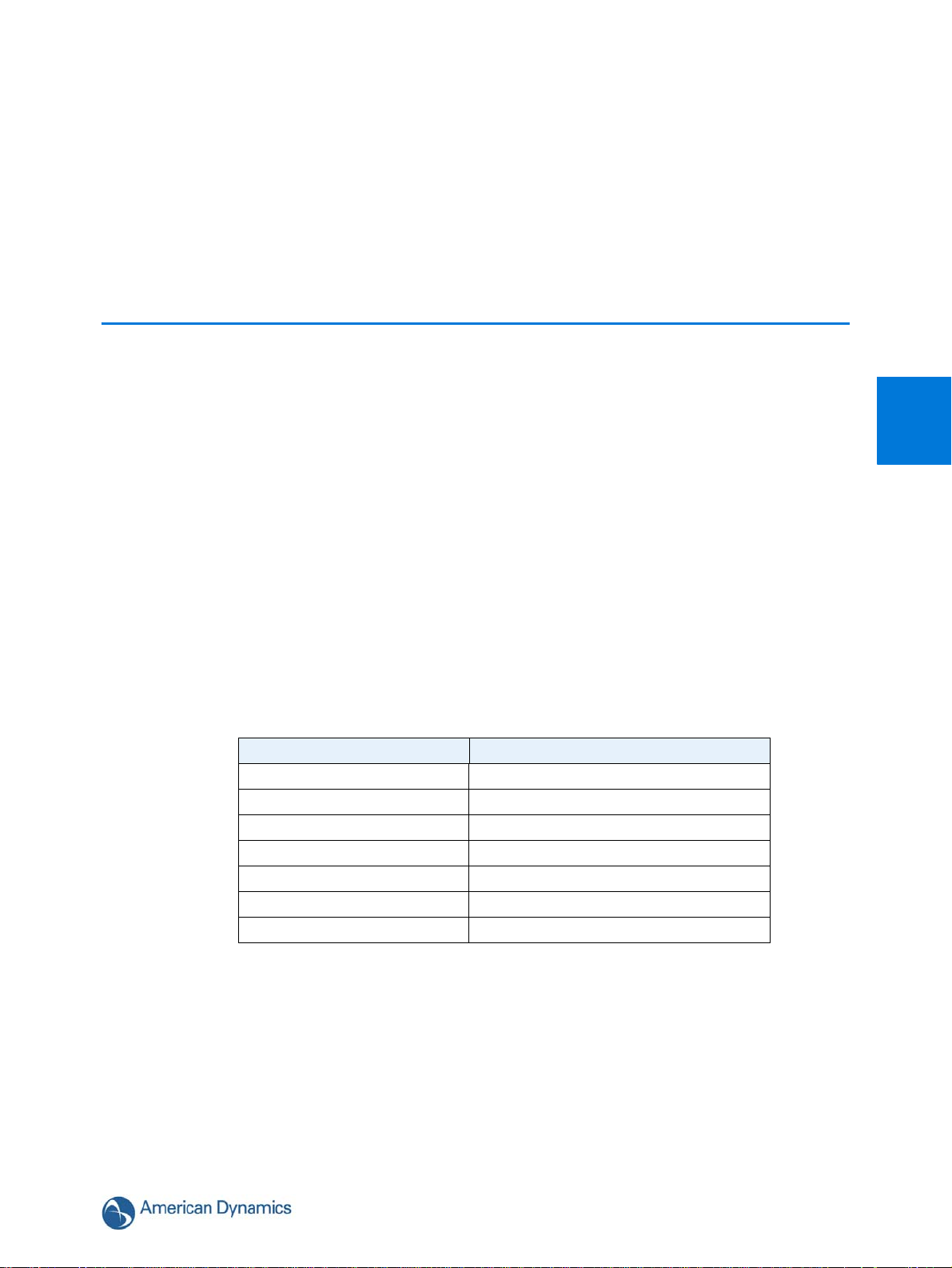
The dome is available in the following configurations:
Illustra 625 PTZ, 1080p, 20x indoor, no bubble, non-vandal, black ADCi625-P132
Illustra 625 PTZ, 1080p, 20x indoor, Feature Plus, no bubble, nonvandal, black
Illustra 625 PTZ, outdoor, Feature Plus, clear, non-vandal, white ADCi625-P222
Illustra 625 PTZ, outdoor, Feature Plus, clear, vandal, white ADCi625-P221
Illustra 625 PTZ, outdoor, Feature Plus, smoked, vandal, white ADCi625-P223
Illustra 625 PTZ, outdoor, Feature Plus, smoked, non-vandal, white ADCi625-P224
Illustra 625 PTZ, outdoor, smoked, vandal, white ADCi625-P123
Illustra 625 PTZ, outdoor, smoked, non-vandal, white ADCi625-P124
Illustra 625 PTZ, outdoor, clear, vandal, white ADCi625-P121
Illustra 625 PTZ, outdoor, clear, non-vandal, white ADCi625-P122
Introduction
1
Illustra 625 PTZ Model Description Product Codes
ADCi625-P232
1-1
Page 12

Introduction
1-2 Configuration and User Guide
Page 13
This chapter provides detailed instructions on how to install the Illustra 625 PTZ camera. You may
also refer to the printed Quick Install Guide provided with the dome.
Camera Mounts
Refer to the Quick Reference Guide supplied with the mount for installation instructions.
Please refer to the American Dynamics website or contact your American Dynamics Sales
Representative for more information on the various mounts and accessories that can be used with
the Illustra 625 PTZ Camera.
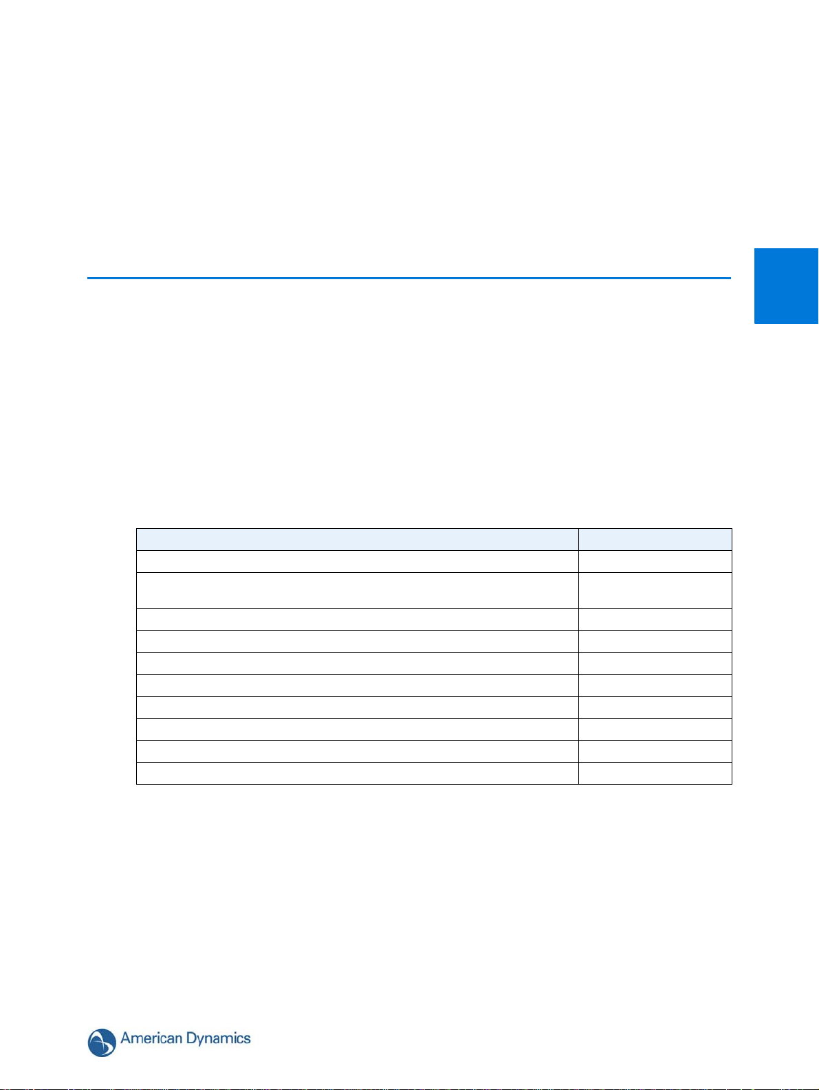
Network Settings
The following provides the default settings for the Illustra 625 PTZ camera and can be used for
reference during installation if required.
Camera Name Illustra625-xxx
DHCP Enabled
IP Address 192.168.1.168
Subnet Mark 255.255.255.0
Default Gateway 0.0.0.0
DNS 0.0.0.0
HTTP Port 80
Installation
2
Setting Default
2-3
Page 14
Installation
Installation Process
2-4 Configuration and User Guide
Page 15

Illustra Connect
Illustra Connect is American Dynamics camera discovery tool and is supplied with the Illustra 625
PTZ Camera on the CD.
Connecting to IP cameras and configuring them can be a time-consuming and error-prone
process. Typing static IP addresses, or naming cameras without seeing where they are pointed,
often results in longer installations. Illustra Connect eliminates all of these issues with a unique
feature set that includes a one-touch IP conflict resolver and snapshot tool. Simply bring up all of
the cameras out of the box, enter the IP range provided by the customer's IT department and hit
"OK."
Key functions of Illustra Connect are:
• “Resolve All Conflicts” button instantly alerts you to all IP addresses that are the same and
provides a number of options to fix issues
• Greatly reduces installation time by automatically supplying static IP addresses from a
configurable range of IP addresses
• Snapshot views of all of the cameras
• “Save Device List” allows you to create a .csv file of all information regarding the camera
settings
• Set IP addresses via DHCP
• Configure IP settings and rename cameras
• Upload firmware to individual or a selectable group of cameras
Installation
2
• Set date and time or direct the cameras to a specific NTP server
• Assign user name and password
• Uses icons common to victor unified client to display camera status
• Compatible with American Dynamics IP cameras
2-5
Page 16

Installation
Note
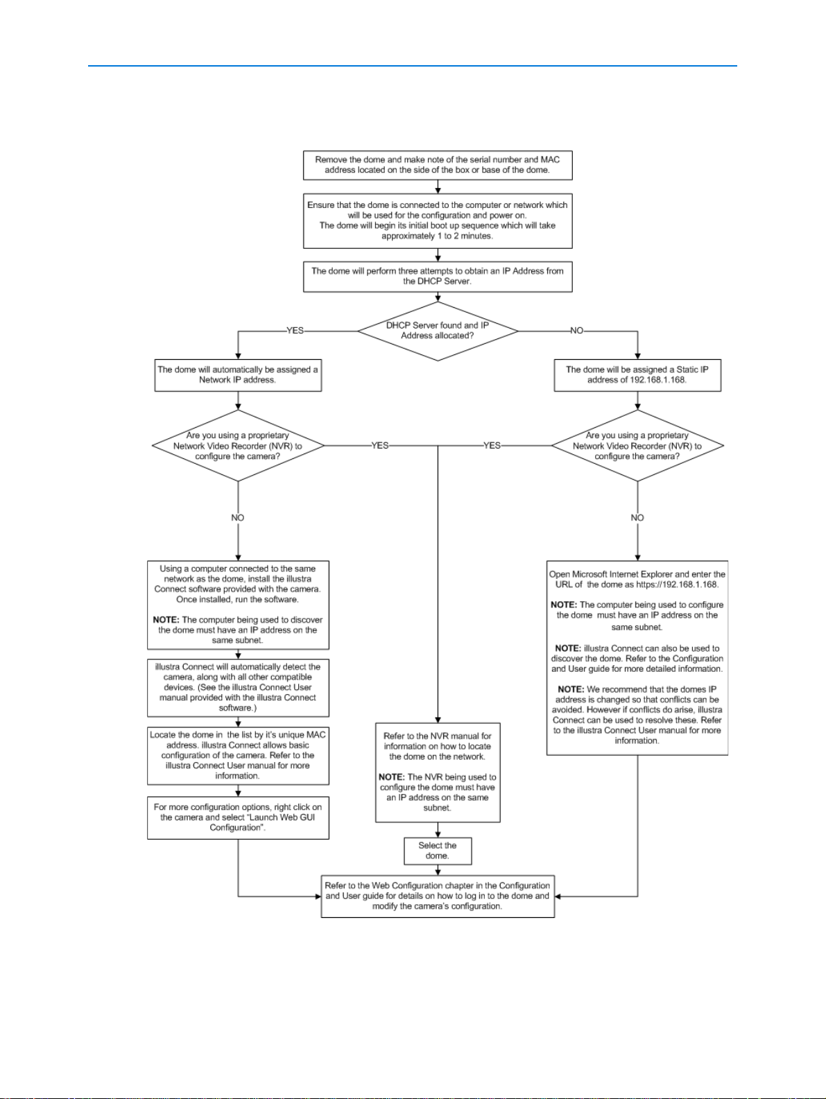
Install and Detect the Illustra 625 PTZ Camera
The following provides detailed information for installing and accessing the dome.
Installation using DHCP and Illustra Connect
The following provides information for installing the dome on your network using the Illustra
Connect discovery tool.
Illustra Connect enables automatic discovery of compliant devices on IP networks and is the
recommended method for installation and detection of the dome on the network.
The Illustra Connect will only discover devices on the same subnet as it’s host computer.
Therefore the dome and the computer being used to configure it must be on the same subnet.
Procedure 2-1 Installing the Illustra 625 PTZ Camera using Illustra Connect
Step Action
1 Using the Quick Start Guide install and connect the dome to the computer or network
which will be used for the configuration and power on.
The dome will begin its initial boot up sequence which will take approximately 1 to 2
minutes.
2 When using a DHCP Server the dome will automatically be assigned a Network IP
address.
3 Using a computer which is connected to the same network and subnet, install the Illustra
Connect software that is provided with the dome. Refer to the Illustra Connect manual for
more information.
4 When the installation is complete, run Illustra Connect. It will search the network and
display all compliant devices, including the dome.
5 Select the dome you wish to configure, locating it by it’s unique MAC address. Illustra
Connect allows basic configuration of the dome.
Refer to the Illustra Connect manual for more information.
6 Right-click the dome and select Launch Web GUI Configuration.
7 Refer to the Web Configuration chapter for details on how to log in to the dome and modify
the configuration.
- End -
2-6 Configuration and User Guide
Page 17

Installation
Note
Note
Installing the Illustra 625 PTZ Camera using DHCP Server Logs
Procedure 2-2 Installing the Illustra 625 PTZ Camera using DHCP Server Logs
Step Action
1 Using the Quick Start Guide install and connect the dome to the computer or network
which will be used for the configuration and power on.
The dome will begin its initial boot up sequence which will take approximately 1 to 2
minutes.
2 When using a DHCP Server the dome will automatically be assigned a Network IP
Address.
3 View the DHCP Server system logs and make note of the IP address assigned to the
dome.
4 Open Microsoft Internet Explorer and enter the URL of the dome as shown in the DHCP
Server log.
The computer being used to configure the dome must have an IP address on the
same subnet.
2
5 Refer to the Web Configuration chapter for details on how to log in to the dome and
modify the configuration.
- End -
Installation without a DHCP Server using a Static IP Address
The following provides information for installing the dome on your network when no DHCP Server
is available. In this situation the dome will be assigned a Static IP Address.
1 We recommend that once you are logged into the Web Configuration pages you change the
Static IP Address of the dome so that conflicts can be avoided when using the same Static IP
Address to setup additional cameras. Refer to
address of the dome.
2 In a situation where IP address conflicts arise, Illustra Connect can be used to discover the
device. Refer to IP Address Conflicts in the Illustra Connect User Guide for further information.
Procedure 2-3 Installing the Illustra 625 PTZ Camera when a DHCP Server is not
available
TCP/IP for information on changing the IP
Step Action
1 Using the Quick Start Guide install and connect the dome to the computer or network
which will be used for the configuration and power on.
2-7
Page 18

Installation
Note
The dome will begin its initial boot up sequence which will take approximately 1 to 2
minutes.
2 The dome will attempt to obtain an IP Address from the DHCP Server. When no DHCP
Server is available the dome will be assigned a Static IP address of 192.168.1.168.
3 Open Microsoft Internet Explorer and enter the URL of the dome as https://192.168.1.168.
1 The computer being used to configure the dome must have an IP address on
the same subnet.
2 Illustra Connect can also be used to discover the dome when using a Static IP
Address. Refer to
Procedure 2-1 Installing the Illustra 625 PTZ using Illustra
Connect and begin at Step 3.
4 Refer to the Web Configuration chapter for details on how to log in to the dome and modify
the configuration.
- End -
2-8 Configuration and User Guide
Page 19

Web Configuration
Note
This section details how to configure the dome using the built-in Web Configuration feature.
Depending on user access you can view Live video and control the camera through PTZ controls
as well as changing the settings for the camera environment.
1 Adobe Reader must be installed to view the online help.
2 To view the Live Video Pane the latest version of QuickTime must be installed and enabled on
the computer running the browser session.
3 Web Configuration sessions timeout after a period of inactivity.
4 Only users with administrative rights can access all the areas of the Web Configuration pages.
3
3-9
Page 20

Web Configuration
Note
Log in and Log Off the Dome
Logging in to the Dome
Use the following procedure to access the dome Web GUI.
Procedure 3-1 Log in to the Dome
Step Action
1 Refer to the Installation Chapter for details on how to connect the dome to your network or
computer.
2 When the dome is selected the sign in page will be displayed.
3 Select your preferred language from the drop down menu.
The default language is ‘English’.
4 Enter the username in the Username text box.
5 Enter the password in the Password text box.
6 Select Log in.
Depending on the access rights of the user account, there may be specific camera
functions that are unavailable. All camera functions are described in this manual.
The default Username is admin and the default Password is admin. To maintain
security the password on the admin account should be changed. Refer to
Procedure 7-5 Change User Password.
- End -
Logging out of the Dome
Use the following procedure to log off the dome Web GUI.
Procedure 3-2 Log off the Dome
Step Action
1 Select Log Off in the upper right hand corner of the Web GUI.
You will be logged off the dome and sign in page will be displayed.
- End -
3-10 Configuration and User Guide
Page 21

User Accounts
There are three types of user account that can be used to access the dome:
• administrator
• operator
•user
Refer to Appendix A: User Account Access for detailed information on access areas.
To add a new user refer to Procedure 7-4 Add a User.
Administrator Access
The administrator account provides full access to the dome. This user account has access to all of
the cameras functions and information.
Operator Access
The operator account provides the following access:
• View Menu: Full access to Picture Settings. Presets, Patterns, Privacy Zones and Scans can be
created, edited, viewed, deleted and activated.
• Program Menu: Sequences can be created, edited and viewed.
• Camera Configuration: PTZ, Video, Stored Audio and Home Position can be edited, viewed
and activated.
• Networking: User account password can be changed.
• Information: Model information, Statistics, Environmental and Current Faults can be viewed.
Web Configuration
3
User Access
The user account provides the following access:
• View Menu: Presets, Patterns, Privacy Zones and Scans can be viewed and activated.
• Program Menu: Sequences can be viewed and activated.
• Camera Configuration: View audio list and listen to stored audio.
• Networking: User account password can be changed.
• Information: Model information can be viewed.
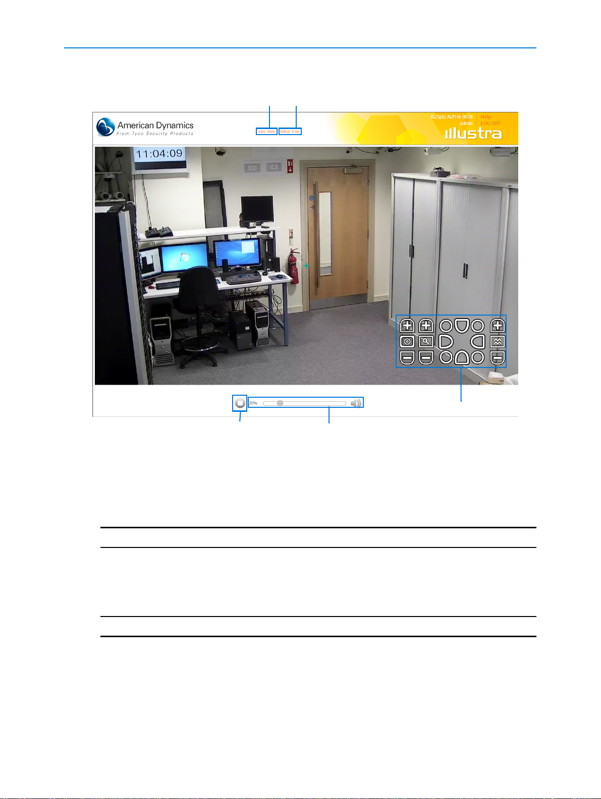
The Dome Web GUI Interface
When logged into the dome the screen will display the live video feed full screen as seen in Figure
3-1 Live Full Screen View.
Refer to GUI Icons for details on the icons used throughout the Web GUI.
Refer to Configuring the Web Video Stream to edit display settings.
3-11
Page 22
Web Configuration
Full Screen Live Video Setup Menus
Start/Stop Video Volume Control
GUI Camera Controls
Figure 3-1 Live Full Screen View
Accessing the Setup Menus from Full Screen Live View
Setup menus within the Web GUI are restricted by user account access levels.
Procedure 3-3 Access Setup Menus from Full Screen Live View
Step Action
1 When displaying full screen live video select Setup View in the GUI banner to access the
setup menus.
The Information page will be displayed.
- End -
Displaying Full Screen Live Video
Display the live video feed full screen on screen.
3-12 Configuration and User Guide
Page 23
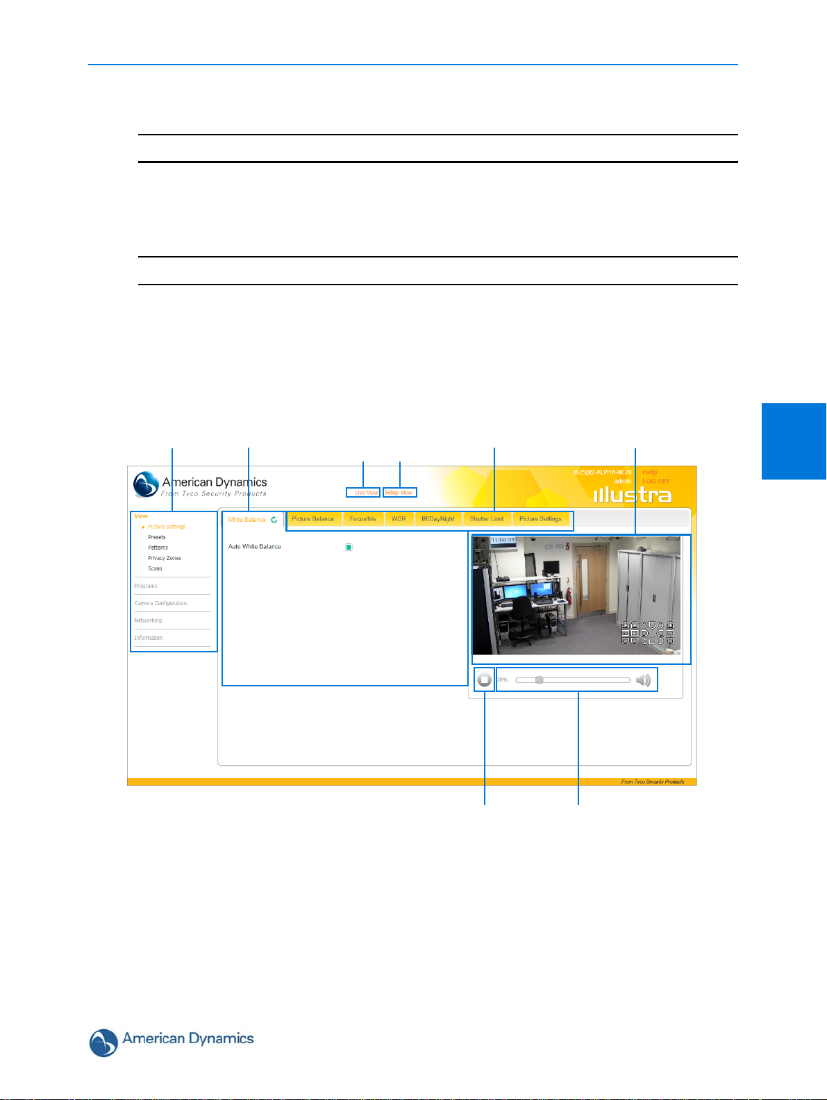
Procedure 3-4 Display Live Video Full Screen
Menus Tabs
Start/Stop Video
Live Video Pane
Volume Control
Selected Tab
Full Screen Live Video Access Menus
Step Action
1 Select Live View in the GUI banner.
The live video feed will displayed full screen. Refer to Configuring the Web Video Stream
to edit display settings.
Overview of the Web GUI
Figure 3-2 The Dome Web GUI provides an overview of the Illustra 625 PTZ Web GUI.
Figure 3-2 The Dome Web GUI
Web Configuration
- End -
3
3-13
Page 24
Web Configuration
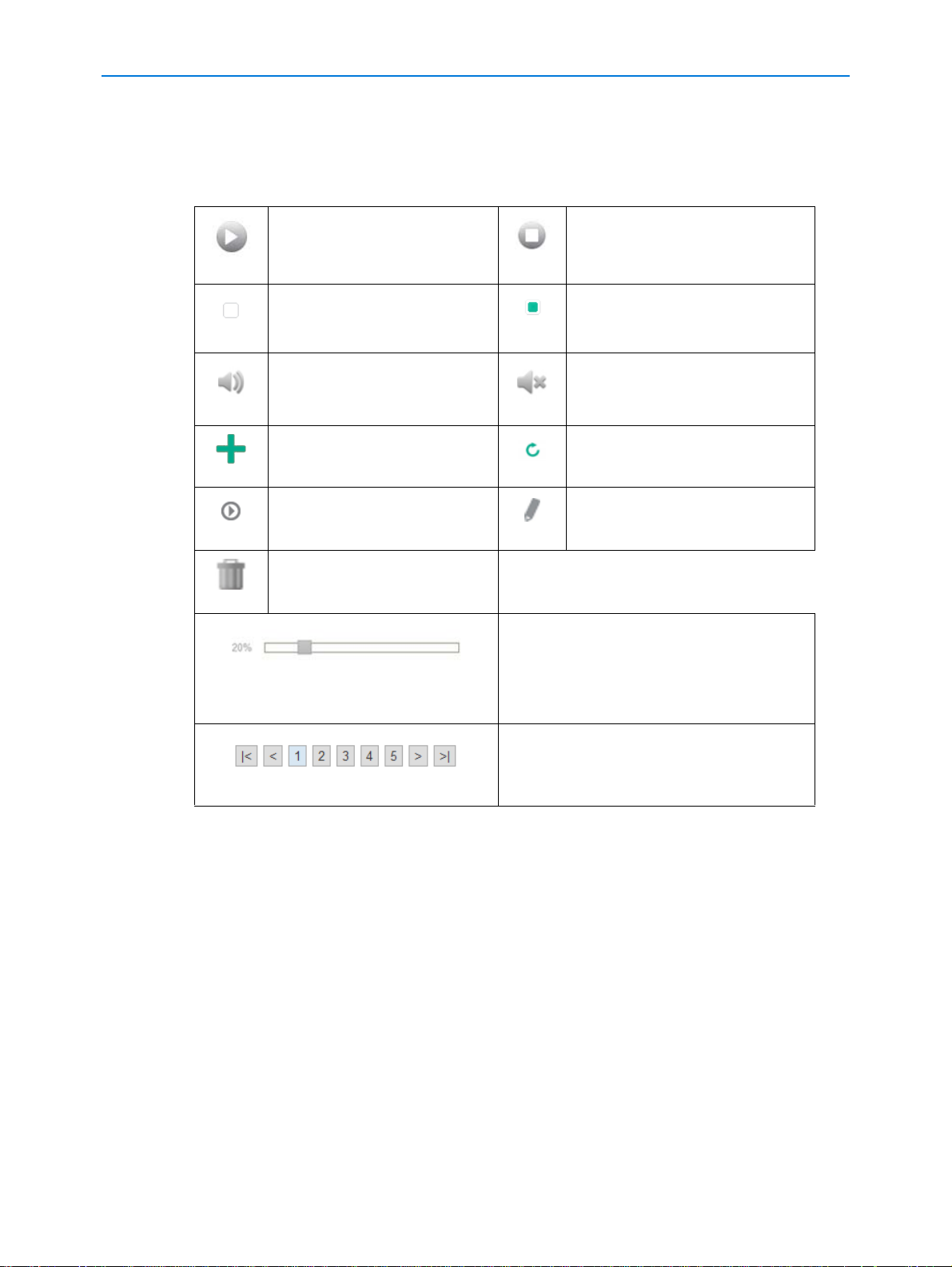
GUI Icons
The following provides information on the icons used throughout the dome interface. These icons
will be referenced throughout this manual:
Select to start the live video
pane.
Check box, deselected. Check box, selected.
Volume is active. Use the
Volume Control slider bar to
adjust the volume.
Pan and tilt quick control Refresh the current tab.
View or activate the
corresponding function.
Delete the corresponding
function.
Slider bar - The slider bar can be moved
left or right using the mouse. For fine
adjustments, select the slider bar with the
mouse and use the left and right arrow
keys on the PC keyboard to adjust the
slider.
Select the page number or arrows to
navigate the pages.
Select to stop the live video
pane.
Volume has been muted.
Edit the corresponding function.
Viewing Live Video via the Live Video Pane
The live video pane provides a simple way to view the video inputs from the dome when using the
setup menus. The live viewing page however is not intended to be the primary way of viewing the
video on the dome; this should be performed using the Network Video Recording device.
Viewing Live Video via the Live Video Pane
The Live Video Pane is accessible to any authorized user and is displayed when accessing the
setup menus. It is not displayed on the following pages; Scheduled Tasks, Alarms, Logs and
Current Faults.
3-14 Configuration and User Guide
Page 25
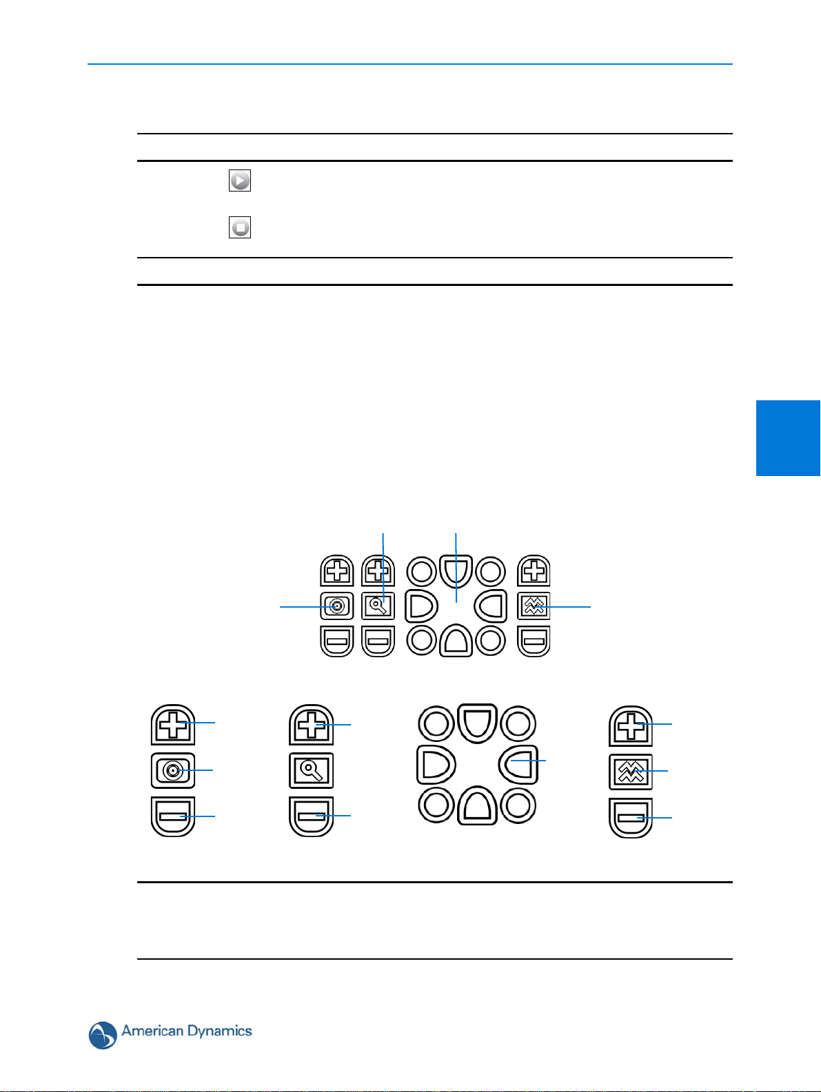
Procedure 3-5 Viewing Live Video via the Live Video Pane
Note
Iris
Focus
Zoom
Pan/Tilt Control
Iris Zoom FocusPan/Tilt Movement
Open
Close
Near
Far
In
Out
Pan/Tilt
(outer rim)
Auto Iris
Auto Focus
Step Action
1 Select to start the live web video.
Refer to Configuring the Web Video Stream to edit display settings.
2 Select to stop the live web video.
- End -
Controlling the Dome using Camera Controls
The dome may be controlled using the on-screen controls in the Live Video Pane.
Web Configuration
GUI Camera Controls
The following provides information on the controls that are available for the on-screen dome
control. The camera control overlay is visible when video is displayed on the Live Video Pane.
3
It is possible for two users to access live viewing at the same time however only one user may
control the camera at any time. Camera control operates on a “last come, first served” basis,
therefore when a new user logs into the camera from a different browser and starts a camera
control session the original user will lose their camera control session.
3-15
Page 26
Web Configuration
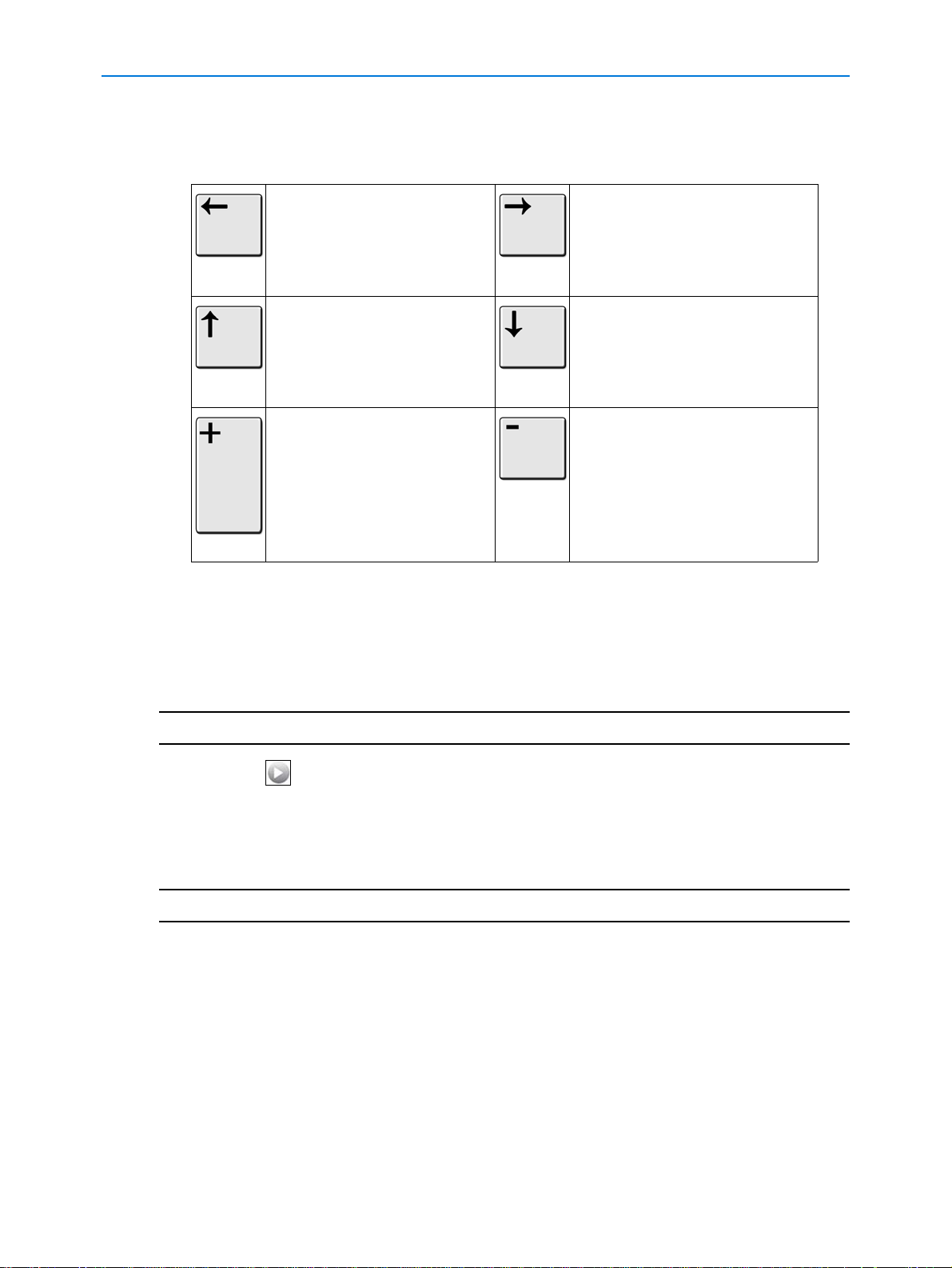
Controlling the camera via Keyboard Shortcuts
The following keyboard shortcuts can be used to control the dome:
Pan Left Pan Right
Tilt Up Tilt Down
Zoom In Zoom Out
Controlling the camera via Camera Controls
The dome may be controlled using the on-screen controls in the Live Video Pane.
Procedure 3-6 Controlling the camera via the Live Video Pane
Step Action
1 Select to start the live web video.
The live video pane will display the current camera view.
2 Select the camera control item on the overlay to activate the control.
Refer to GUI Camera Controls for information on specific camera controls.
- End -
Controlling the Pan/Tilt Control via Click and Drag
Controlling the dome using the mouse allows for slower camera movement which will provide
maximum accuracy.
3-16 Configuration and User Guide
Page 27
Web Configuration
Procedure 3-7 Controlling Pan/Tilt via Click and Drag using the Live Video
Pane
Step Action
1 Select to start the live web video feed.
The live video pane will display the current camera view.
2 Move the cursor to the pan and tilt quick control icon in the center of the video pane.
3 Click and drag the cursor to set the direction and speed of the camera.
• A red arrow will appear showing the direction of camera movement.
• The camera’s movement speed increases as the arrow is moved further from
the cursor origin mark.
- End -
Zooming Using the Mouse Scroll Wheel
Control the zoom function using a scroll wheel mouse.
Procedure 3-8 Zooming via the mouse scroll wheel using the Live Video
Pane
Step Action
1 Select to start the live web video feed.
The live video pane will display the current camera view.
2 Refer to Controlling the camera via Camera Controls or Procedure 3-7 Controlling
Pan/Tilt via Click and Drag using the Live Video Pane to point the camera at the target.
3 Scroll the mouse wheel upwards (zoom in) and downwards (zoom out).
- End -
Double-click to Center using the mouse
Click on the live video pane to automatically center the camera display.
3
Procedure 3-9 Activate Double-click to Center using the mouse
Step Action
1 Select to start the live web video feed.
The live video pane will display the current camera view.
2 Using the mouse, double-click on the area of interest in the live video pane.
3-17
Page 28
Web Configuration
The PTZ will adjust to display the area of interest in the center of the live video pane.
3 Repeat step 2 to select a new area of interest.
- End -
PTZ to a Selected Area using the mouse
Draw a rectangle on the live video pane to have the camera PTZ adjust to the selected area of
interest.
Procedure 3-10 Activate PTZ to a Selected Area using the mouse
Step Action
1 Select to start the live web video feed.
The live video pane will display the current camera view.
2 Click and drag on The live video pane to highlight the area to display.
3 A red outline will appear to show the selected area of interest.
Release the mouse button, the PTZ will adjust to display the area of interest in the center
of the live video pane.
4 Repeat step 2 to select a new area of interest.
- End -
3-18 Configuration and User Guide
Page 29
When the view menu is selected Figure 4-1 View Menu will be displayed.
Figure 4-1 View Menu
View Menu
4
The View Menu provides access to the following dome settings and functions:
• Picture Settings
•Presets
• Patterns
• Privacy Zones
•Scans
4-19
Page 30

View Menu
Note
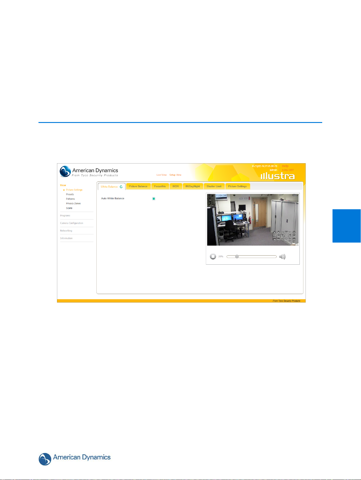
White Balance
White balance (the ability to keep whites looking white) is normally compensated for automatically
via the default Auto White Balance (AWB) setting. Manual White Balance (MWB) is available when
specific color temperature settings want to be set and preserved. This can be done using the red
and blue slider adjustments set for optimal viewing.
Configuring White Balance
Adjust the white balance.
Procedure 4-1 Configure Auto White Balance
Step Action
1 Select Picture Settings from the View menu.
The White Balance tab displays.
2 Select the Auto White Balance check box to enable auto white balance.
Or
Deselect the Auto White Balance check box to disable auto white balance and enable
Manual White Balance. Manual White Balance can be adjusted using the red and blue
sliders. Refer to
The default setting is Auto White Balance ‘enabled’.
Procedure 4-2 Configure the Red and Blue Balance.
- End -
Configuring the Red and Blue Balance
Adjust the red and blue balance.
Procedure 4-2 Configure the Red and Blue Balance
Step Action
1 Select Picture Settings from the View menu.
The White Balance tab displays.
2 Select to start the live web video.
The live video pane will display the current camera view.
3 Deselect the Auto White Balance check box to disable auto white balance.
When Automatic White Balance is first switched from enabled to disabled, the red
and blue values displayed are based on the current feedback values from the
camera.
4-20 Configuration and User Guide
Page 31

4 Use the slider bars to change the Red and Blue balance. The live video pane will update
to display the new settings.
The red and blue values range from 0% to 100%.
Picture Balance
Adjust brightness, contrast and saturation of the image displayed in the Live Video Pane.
Adjusting Picture Balance
Configure brightness, contrast and saturation.
Procedure 4-3 Adjust the Brightness, Contrast and Saturation
Step Action
View Menu
- End -
1 Select Picture Settings from the View menu.
2 Select the Picture Balance tab.
The Picture Balance tab displays.
3 Select to start the live web video.
The live video pane will display the current camera view.
4 Use the slider bars to change:
• Brightness
• Contrast
• Saturation (color level)
The live video pane will update to display the new settings.
The values range from 0% to 100%.
The default values are 50%.
- End -
Restoring Picture Balance
Use this procedure to restore picture balance settings to factory default.
4
4-21
Page 32

View Menu
Note
Procedure 4-4 Restore Picture Balance Defaults
Step Action
1 Select Picture Settings from the View menu.
2 Select the Picture Balance tab.
The Picture Balance tab displays.
3 Select Defaults to restore the default settings.
The default settings are 50%.
- End -
Focus/Iris
When Auto Focus and Iris are enabled the camera automatically compensates for scene changes
that effect focal length (focus) and light levels (iris).
If Auto Iris and Focus are turned off a feature called ‘Return Settings’ (refer to Procedure 6-3
Enable/Disable Return Settings) can be configured to automatically return Focus and Iris to Auto
modes after the dome is commanded to move a sufficient amount (about half a screen width, and
more than a few seconds).
Auto Focus and Auto Iris can also be adjusted, enabled and disabled using GUI Camera Controls.
Setting Auto Focus
Enable or disable auto focus on the dome.
Procedure 4-5 Enable/Disable Auto Focus
Step Action
1 Select Picture Settings from the View menu.
2 Select the Focus/Iris tab.
The Focus/Iris tab displays.
3 Select the Auto Focus check box to enable auto focus.
Or
Deselect the Auto Focus check box to disable auto focus.
The default setting is ‘Enabled’.
- End -
4-22 Configuration and User Guide
Page 33

Setting Auto Iris
Enable or disable auto iris on the dome.
Procedure 4-6 Enable/Disable the Dome Auto Iris
Step Action
1 Select Picture Settings from the View menu.
2 Select the Focus/Iris tab.
The Focus/Iris tab displays.
3 Select the Auto Iris check box to enable auto iris.
Or
Deselect the Auto Iris check box to disable auto iris.
The default setting is ‘Enabled’.
- End -
View Menu
Wide Dynamic Range
Configuring WDR
Wide Dynamic Range (WDR) is a feature that allows viewing of high contrast scenes that include
both bright and low light areas in the same field of view (FOV).
A typical use for this feature would be viewing a scene with both indoor and outdoor lighting
conditions simultaneously, for example, in a warehouse area with an open bay door.
Procedure 4-7 Disable/Enable Wide Dynamic Range (WDR)
Step Action
1 Select Picture Settings from the View menu.
The white balance tab displays.
2 Select the WDR tab.
The WDR tab displays.
3 Select the WDR check box to enable WDR.
Or
Deselect the WDR check box to disable WDR.
The default setting is ‘Disabled’.
4
- End -
4-23
Page 34

View Menu
IR/DayNight Mode
IR/DayNight Mode utilizes a series of specific camera functions to dramatically enhance low light
performance.
When needed one of these functions, the True TDN mechanism, removes an IR Cut Filter (IRCF)
from in front of the imager allowing the camera to see in black and white (BW) and utilize
additional near-infrared energy found in many lighting sources like halogen, moonlight, etc.
This, along with slowing down another function, the shutter speed, significantly improves low light
performance rendering clear images where none could be viewed previously.
IR Mode
When the camera is in B/W mode it can utilize or “see” near-IR illumination; something the human
eye cannot do. This can be extremely powerful when the dome is paired with 850~950nm IR
illuminators. With this combination a scene can be well lit with IR light that the dome can see but
people cannot. This is great for areas where externally lighting is not allowed or there is a need for
covert security.
Normal, or visible light, and IR light have different focal points. The camera has 3 IR modes to help
optimize focus capabilities and achieve sharper IP pictures when using these light sources. Please
refer to
Table 4-1 Corresponding IR Switching with IR illumination for recommended settings.
Table 4-1 Corresponding IR Switching with IR illumination
IR Curve For Lighting Sources Visibility
Visible
850nm 850nm IR illuminators Only the dome (in BW) can utilize this
950nm 950nm IR illuminators Only the dome (in BW) can utilize this
Normal Lighting –, Florescent,
Incandescent, Sunlight, etc
Both the dome (in Color and BW) and the
human eye can utilize these types of
illumination sources
type of illumination source. The human
eye cannot.
type of illumination source. The human
eye cannot
Configuring IR
Adjust IR mode on the dome.
Procedure 4-8 Configure IR Mode
Step Action
1 Select Picture Settings from the View menu.
2 Select the IR/DayNight Mode tab.
The IR/DayNight Mode tab displays.
3 Select an IR Mode setting:
4-24 Configuration and User Guide
Page 35

View Menu
• visible - Most common, visible lighting sources.
• 850nm - Ideal for 850nm IR Illuminators.
• 950nm - Ideal for 950nm IR Illuminators.
The default setting is ‘visible’.
- End -
Day Night Mode
The dome provides a black-and-white (B/W) mode to improve camera performance when the light
level falls below certain thresholds. This allows clear images to be obtained under low-light
conditions. There are five Day/Night settings: Off, On, Auto High, Auto Mid and Auto Low.
Configuring Day Night Mode
Procedure 4-9 Configure Day Night Mode
Step Action
1 Select Picture Settings from the View menu.
2 Select the IR/DayNight tab.
The IR/DayNight tab displays.
3 Select a Day Night Mode setting:
• off - disable the Day Night Mode. The camera will operate in color mode only.
• on - enable full-time black and white mode.
• autolow - stays in color mode the longest only switching to BW at the lowest
light levels.
• automid - good balance of Color and BW mode performance.
• autohigh - in color mode this is the least switching in and out of black and white
at the highest light levels of the three.
The default setting is ‘autolow’.
- End -
4
Shutter Limit
In addition to the IR & Day/Night Modes the Illustra i625 PTZ dome provides additional
functionality to help compensate for low-light scenes: Automatic Gain Control (AGC) and Open
Shutter.
4-25
Page 36

View Menu
Note
Automatic Gain Control (AGC)
Amplifies the video signal in scenes when there is not enough light to produce full video levels.
The maximum level of AGC is controlled by the Max Gain control. It is adjustable from 0dB (off) to
37dB. As gain is increased, the sensor noise is also amplified which can result in more noticeable
noise in the image.
Open Shutter
This is a technique that is used for really low light performance applications. It allows the shutter
speed to be slowed down further than normal to allow the sensor to collect more light. The
maximum level of Open Shutter is controlled by the Shutter Speed control. It is adjustable from
1/30 down to ½ second. The slower the Shutter Speed the higher the chance for image blur which
may affect moving object identification. It is only in effect during low light situations where an
image would not be obtainable otherwise and does not affect the camera performance in normal or
bright light situations.
Configuring AGC/Shutter Settings
Adjust Automatic Gain Control and Shutter Settings.
Procedure 4-10 Configure the AGC/Shutter Setting
Step Action
1 Select Picture Settings from the View menu.
2 Select the Shutter Limit tab.
The Shutter Limit tab displays.
3 Select a AGC/Shutter setting:
• AGC off - produces the cleanest image with the least noise but the worst low
light performance.
• AGC on - good low light performance with the chance for some noise.
• openshutter - best for low light performance. However there is a chance for
some noise and some image blur.
The default setting is ‘openshutter’.
If you require “Real Time” video open shutter must be turned off to ensure that the
resulting video quality is acceptable for prosecution purposes.
- End -
4-26 Configuration and User Guide
Page 37

Shutter Speed
Changing the Shutter Speed
Selecting a fast shutter speed will give the least amount of artifacts but reduced low light
performance, a slower shutter speed will give better low light performance but more artifacts will
be visible.
Procedure 4-11 Configure Shutter Speed
Step Action
1 Select Picture Settings from the View menu.
2 Select the Shutter Limit tab.
The Shutter Limit tab displays.
When ‘openshutter’ is selected from the AGC/Shutter setting the Shutter speed section
display.
3 Select a Shutter speed setting from the drop down menu:
•1/2
•1/4
View Menu
•1/8
•1/15
•1/30
The selection will be applied.
The default setting is ‘1/8’.
Max Gain
The Max Gain setting is an upper limit for how much gain can be increased when AGC is enabled.
The trade-off between picture level (brightness) and noise may be adjusted by setting the Max
Gain value. Lower values for Max Gain setting may result in a darker picture but with less noise.
Higher values for Max Gain setting may result in a brighter picture but with more noise.
Configuring Max Gain
Adjust max gain settings on the dome.
4
- End -
4-27
Page 38

View Menu
Note
Procedure 4-12 Configure Max Gain
Step Action
1 Select Picture Settings from the View menu.
2 Select the Shutter Limit tab.
The Shutter Limit tab displays.
When ‘AGC on’ or ‘openshutter’ is selected from the AGC/Shutter Setting the Max gain
section will be displayed.
3 Use the slider bar to change the Max gain setting.
The values range from 1 to 37.
The default setting is 37.
- End -
Picture Settings
The picture options allow you to save the current settings, restore saved settings or restore to
factory default settings.
Saving Picture Settings
Save the current picture settings to the dome.
If the dome is rebooted or powered off, upon restart the picture settings will return to the last saved
settings. If picture settings have not been saved, upon restart the dome will use the default picture
settings.
Procedure 4-13 Save Current Picture Settings
Step Action
1 Select Picture Settings from the View menu.
2 Select the Picture Settings tab.
The Picture Settings tab displays.
3 Select Save to save and retain the current picture settings.
- End -
4-28 Configuration and User Guide
Page 39

Restoring Saved Picture Settings
Restore previously saved picture settings.
Procedure 4-14 Restore Saved Picture Settings
Step Action
1 Select Picture Settings from the View menu.
2 Select the Picture Settings tab.
The Picture Settings tab displays.
3 Select Restore to restore the previously saved picture settings.
- End -
Restoring Factory Default Picture Settings
Restore the factory default picture settings.
View Menu
Procedure 4-15 Restore Factory Picture Settings
Step Action
1 Select Picture Settings from the View menu.
2 Select the Picture Settings tab.
The Picture Settings tab displays.
3 Select Defaults to restore the factory picture settings.
- End -
4
4-29
Page 40

View Menu
Presets
A Preset is a pre-positioned camera scene that you program for cameras installed with pan/tilt and
motorized lens capability. Up to 96 presets can be programmed for the dome.
Adding a new Preset
Create a new preset position on the dome.
Procedure 4-16 Add a Preset
Step Action
1 Select Presets from the View menu.
The Preset tab displays.
2 Select to start the live web video.
The live video pane will display the current camera view.
3 Adjust the camera view as required.
• Pan, Tilt and Zoom.
• Focus Mode and Iris Mode.
Refer to GUI Camera Controls to make the required adjustments.
4 The following camera controls can be modified and saved as part of the preset and
accessed via the Picture Settings menu:
• White Balance
• Picture Balance
• Wide Dynamic Range (WDR)
• IR/DayNight
• Shutter Limit
5 In a numbered slot on the preset table, select to add the new preset.
6 Enter the preset name in the Preset Name text box.
7 Select Add to save the preset.
Or
Select Cancel.
- End -
Viewing a Preset
View an existing preset position.
4-30 Configuration and User Guide
Page 41

Procedure 4-17 View a Preset
Step Action
1 Select Presets from the View menu.
The Preset tab displays.
2 Select to start the live web video.
The live video pane will display the current camera view.
3 Select to activate the corresponding preset.
The live video pane will update to display the selected preset.The preset will display until
interrupted by a camera command, pattern, scan or alarm.
- End -
Editing a Preset
Edit an existing preset position.
View Menu
Procedure 4-18 Edit an existing Preset
Step Action
1 Select Presets from the View menu.
The Preset tab displays.
2 Select to start the live web video feed.
The live video pane will display the current camera view.
3 Select to activate the corresponding preset.
The live video pane will update to display the selected preset.
4 Select to edit the corresponding preset.
5 Edit the preset name in the Preset Name text box if required.
6 Adjust the camera view as required.
• Pan, Tilt and Zoom.
• Focus Mode and Iris Mode.
Refer to GUI Camera Controls to make the required adjustments.
7 The following camera controls can be saved as part of the preset and accessed via the
Picture Settings menu:
4
4-31
Page 42

View Menu
Note
• White Balance
• Picture Balance
• Wide Dynamic Range (WDR)
• IR/DayNight
• Shutter Limit
8 Select Add to save the updated preset.
You will be prompted to confirm the update.
9 Select OK to save the changes.
Or
Select Cancel.
- End -
Deleting a Preset
Delete an existing preset position from the dome.
Procedure 4-19 Delete a Preset
Step Action
1 Select Presets from the View menu.
The Preset tab displays.
2 Select to delete the corresponding preset.
You will be prompted to confirm the deletion.
You cannot delete a preset while it is associated with another camera function. To
remove the preset refer to the associated camera function.
3 Select OK to confirm the deletion.
Or
Select Cancel.
- End -
4-32 Configuration and User Guide
Page 43

Patterns
Note
Note
A pattern is a series of pan, tilt, zoom and focus movements which can be saved to the dome. A
maximum of 17 patterns can be programmed for the dome with an unlimited duration.
1 The Illustra 625 PTZ provides Apple Peel, which is a predefined pattern stored on the camera
by default that covers the entire viewing area. This pattern slowly pans 360° starting at the
ceiling line. It then tilts 30° and pans 360° again, repeating until the entire viewing area is
covered. The pattern will repeat continuously until interrupted by a camera command, preset,
scan or alarm.
2 There are two Apple Peel patterns on the dome by default. Apple Peel pattern one is read only
and cannot be edited or deleted. Apple Peel pattern two can be edited and if necessary
deleted from the dome.
Adding a Pattern
Create a new pattern.
View Menu
A 15 minute time out period is implemented when adding a pattern. If no command is received
within the time out period the Add a Pattern procedure will automatically terminate.
Procedure 4-20 Add a Pattern
Step Action
1 Select Patterns from the View menu.
2 Select the Record tab.
The Record tab displays.
3 Select to start the live web video feed.
The live video pane will display the current camera view.
4 Enter the pattern name in the Pattern Name text box.
5 Select Start.
The Record page will update with an Add and Cancel button.
6 Use the GUI Camera Controls to configure the required pattern settings.
The following controls can be saved as part of the pattern:
• Focus
4
•Iris
7 Select Add to save the pattern.
Or
4-33
Page 44

View Menu
Note
Select Cancel.
- End -
Running a Pattern
Activate an existing pattern.
Procedure 4-21 Run a Pattern
Step Action
1 Select Patterns from the View menu.
The Patterns tab displays.
2 Select to start the live web video feed.
The live video pane will display the current camera view.
3 Select to activate the corresponding pattern.
The live video pane will update to display the selected pattern.The pattern will run
continuously until interrupted by a camera command, pattern, scan or alarm.
- End -
Deleting a Pattern
Delete an existing pattern.
Procedure 4-22 Delete a Pattern
Step Action
1 Select Pattern from the View menu.
The Patterns tab displays.
2 Select to delete the corresponding pattern.
You will be prompted to confirm the deletion.
You cannot delete a pattern while it is associated with another camera function. To
remove the pattern refer to the associated camera function.
3 Select OK to confirm the deletion.
Or
4-34 Configuration and User Guide
Page 45

Select Cancel.
- End -
Repeating a Pattern
Use this procedure to have a pattern repeat until interrupted by a new command.
Procedure 4-23 Enable/Disable Repeat a Pattern
Step Action
1 Select Pattern from the View menu.
The Patterns tab displays.
2 Select the Repeat tab.
3 Select the Repeat Pattern check box to allow the pattern to repeat continuously.
Or
View Menu
Deselect the Repeat Pattern check box to allow pattern to run one time only.
The default setting is ‘Enabled’.
- End -
4
4-35
Page 46

View Menu
Note
Privacy Zones
Privacy Zones are “masked” sections of the dome’s viewing area. These masks prevent operators
of the surveillance system who do not have access to the dome password from viewing these
designated zones. Each zone has four sides, and the zones may overlap to form irregular shapes.
The Privacy Zones move in relation to the dome pan/tilt position.
In addition, the apparent size of the Privacy Zone adjusts automatically as the zoom level is
adjusted. Privacy Zones are useful for high security areas. For example, you might establish a
privacy Zone around a safe’s combination, but still view people approaching or opening the safe.
When Privacy Zones are active, the dome's firmware automatically disables text transparency.
Up to 32 rectangular privacy zones can be used on the dome.
Areas of the Privacy Zone may be exposed during rapid pan / tilt movements of the dome. To
compensate for this limitation, you may want to program the Privacy Zone to be 20 to 25% larger
than the area you want to mask.
Defining a Privacy Zone
Create a privacy zone on the dome.
Procedure 4-24 Define a Privacy Zone
Step Action
1 Select Privacy Zone from the View menu.
2 Select the Add Zone tab.
The Add Zone tab displays.
3 Select to start the live web video feed.
The live video pane will display the current camera view.
4 Adjust the camera view as required.
Refer to GUI Camera Controls to make the necessary adjustments.
5 Enter the privacy zone name in the Privacy Zone text box.
6 Select Draw.
The image will freeze and a still image will be displayed. The Add page updates to display
a Add and Cancel button.
7 Using the cursor locate the start point for the privacy zone, click and drag on the still image
to define the privacy zone area. As the cursor is moved a red shape will appear on the
image which highlights the privacy zone.
8 Release the mouse button.
The selected privacy area will turn red.
9 To reselect an alternative area for the privacy zone repeat steps 7 and 8.
10 Select Add to save the current privacy zone.
Or
4-36 Configuration and User Guide
Page 47

Select Cancel.
Note
When a new privacy zone is created it is automatically enabled, refer to
Procedure 4-25 Enable/Disable a Privacy Zone to modify this setting.
- End -
Enabling or Disabling a Privacy Zone
Select a privacy zone to hide or display on the dome.
Procedure 4-25 Enable/Disable a Privacy Zone
Step Action
1 Select Privacy Zone from the View menu.
The Privacy Zones tab displays.
2 Select to start the live web video feed.
View Menu
The live video pane will display the current camera view.
3 Select to activate the corresponding privacy zone.
The live video pane will update to display the selected privacy zone.
4 Select the corresponding Enabled check box to enable the privacy zone.
Or
Deselect the corresponding Enabled check box to disable the privacy zone.
- End -
Deleting a Privacy Zone
Delete a privacy zone from the dome.
Procedure 4-26 Delete a Privacy Zone
Step Action
1 Select Privacy Zone from the View menu.
The Privacy zones tab displays.
4
4-37
Page 48

View Menu
Note
2 Select the corresponding Delete check box to mark the privacy zone for deletion.
More than one privacy zone can be deleted at a time. The Select All check box
can also be used.
3 Select Delete to delete the selected privacy zones.
You will be prompted to confirm the deletion.
4 Select OK to confirm the deletion.
Or
Select Cancel.
- End -
4-38 Configuration and User Guide
Page 49

Scans
A scan allows you to program left and right scan limits to automate surveillance activities. Once
these scan limits are programmed you can choose to run a smooth scan, stepped scan, or random
scan. When active, the scan repeats until interrupted by a camera command, preset, pattern or
alarm.
Setting Scan Limits
Set left and right scan limits on the dome.
Procedure 4-27 Set Scan Limits
Step Action
1 Select Scans from the View menu.
2 Select the Scan Limits tab.
The Scans Limits tab displays.
3 Select to start the live web video feed.
The live video pane will display the current camera view.
View Menu
4 Adjust the camera view as required to locate the left scan limit.
Refer to GUI Camera Controls to make the necessary adjustments.
5 Select Set Left to set the displayed position as the left limit.
6 Adjust the camera view as required to locate the right scan limit.
7 Select Set Right to set the displayed position as the right limit.
The scan limits have been set and the selected scan will now run within the scan limits set.
- End -
Set Scan Limits to Default Settings
Return the dome to the default scan settings.
Procedure 4-28 Set Scan Limits to Default Settings
Step Action
1 Select Scans from the View menu.
2 Select the Scan Limits tab.
The Scans Limits tab displays.
4
3 Select Defaults.
4-39
Page 50

View Menu
The scan limits will default to Left: 0 and Right: 359.
- End -
Activating a Scan
Activate a scan on the dome, this will run using the scan limits saved in Setting Scan Limits.
Procedure 4-29 Activate a Scan
Step Action
1 Refer to Setting Scan Limits before activating a scan.
2 Select Scans from the View menu.
The Scans tab displays.
3 Select to start the live web video feed.
The live video pane will display the current camera view.
4 Select to activate the corresponding scan.
• smooth - slowly pans between the left and right scan limits, starting at the left
scan limit. When the right scan limit is reached, the scan reverses
• stepped - pans slowly, pausing briefly every 10° between the left and right scan
limits. Once the right scan limit is reached, the scan reverses.
• random - pans randomly between the left and right scan limits. For example, the
scan may start at 10°, then pan right 40° and pause, pan right 20° and pause,
pan left 30° and pause, and pan right until it reaches the right scan limit.
5 The live video pane will update to display the selected scan.The scan will run continuously
until interrupted by a camera command, pattern, preset or alarm.
- End -
4-40 Configuration and User Guide
Page 51

Programs Menu
When the view menu is selected Figure 5-1 Programs Menu will be displayed.
Figure 5-1 Programs Menu
5
The Programs Menu provides access to the following dome settings and functions:
• Sequences
•Alarms
• Scheduled Tasks
• Areas
5-41
Page 52

Programs Menu
Note
Sequences
A Sequence is a sequential display of multiple camera Presets. Sequences provide a methodical
and effective way to monitor multiple areas of interest by switching to different Presets
automatically.
Sequences are created by identifying Preset views to include in the Sequence and specifying a
dwell time that controls how long each Preset remains on-screen before switching to another
Preset.
Up to 16 Sequences can be created, each with 16 steps (Presets).
Adding a Sequence
Create a new sequence on the dome using defined presets. Refer to Adding a new Preset if no
presets have yet been added to the dome.
Procedure 5-1 Add a Sequence
Step Action
1 If no presets have been created refer to Adding a new Preset before continuing to step 2.
2 Select Sequences from the Programs menu.
3 Select the Add Sequence tab.
The Add Sequence tab displays.
4 Enter the sequence name in the Sequence text box.
5 Select a preset from the Preset Name drop-down menu.
6 Enter a dwell time in seconds in the Dwell Time text box.
7 Select Add. The preset is now listed as part of the sequence.
Or
Select Cancel.
8 Repeat steps 5 to 7 to add further presets to the sequence.
Up to 16 presets can be added to a sequence.
9 Select Apply to save the sequence.
- End -
Activating a Sequence
Activate a selected sequence.
5-42 Configuration and User Guide
Page 53

Procedure 5-2 Activate a Sequence
Step Action
1 Select Sequences from the Programs menu.
The Sequences tab displays.
2 Select to start the live web video feed.
The live video pane will display the current camera view.
3 Select to activate the corresponding sequence.
The live video pane will update to display the selected sequence.The sequence will run
continuously until interrupted by a camera command, pattern, preset, scan or alarm.
- End -
Editing a Sequence
Edit an existing sequence.
Programs Menu
Procedure 5-3 Edit a Sequence
Step Action
1 Select Sequences from the Programs menu.
The Sequences tab displays.
2 Select to edit the corresponding sequence.
The sequence will open in the Edit Sequence tab.
3 Edit the sequence name in the Sequence Name text box if required.
4 Select to edit the corresponding preset, the following can be edited:
•Preset Name
To add a new preset to the sequence, move to the next available free slot and select a
preset from the Preset Name drop-down menu.
• Dwell time
5 If required, select to remove the corresponding preset from the sequence.
6 Select Add to save the changes
Or
Select Cancel.
7 Select Apply to save the changes.
5
- End -
5-43
Page 54

Programs Menu
Deleting a Sequence
Delete an existing sequence.
Procedure 5-4 Delete a Sequence
Step Action
1 Select Sequences from the Programs menu.
The Sequences tab displays.
2 Select to delete the corresponding sequence.
You will be prompted to confirm the deletion.
3 Select OK to confirm the deletion.
Or
Select Cancel.
- End -
5-44 Configuration and User Guide
Page 55

Alarms
Note
If using a Illustra 625 PTZ Feature Plus camera it will be possible to configure and trigger alarms.
The dome can be commanded to carry out a specified operation when a alarm is triggered.
Scheduled tasks, return to home, alarms and manual camera control will always begin when they
are selected or scheduled to start. None of these camera actions have a priority over the other. If a
camera action is in progress and a new action is selected or activated the previous action will stop
before the new action is started.
The dome provides four alarm inputs. By connecting alarm devices, such as smoke alarms,
twilight sensors, or motion sensors, to these inputs, you can enhance the usability of your video
surveillance system. You can further improve your video surveillance by assigning a action, such
as a preset or pattern, to start whenever an alarm input changes from normal to abnormal.
• For 15 seconds after being triggered any additional individual input changes on that alarm
source will only be logged and not generate any other action. This is to reduce the effect that any
oscillating alarm source, e.g. if a door is simply vibrating in the wind, causing a series of alarms
to be generated.
• Input alarms are triggered upon change of state. Either from opened to closed or from closed to
open. The camera will report the current state of each input alarms (open or closed) as well as
an active or inactive status in the alarm configuration page. Active alarms will also be visible in
the current faults page.
• The triggering of any input alarm will affect scheduled tasks and delay them until at least 30
seconds has passed since the last digital alarm input was triggered.
Programs Menu
Alarm Actions
Upon triggering each alarm input can be configured to trigger any combination of the following
actions:
• PTZ action: none or a stored preset, pattern, sequence or scan.
• The result of this PTZ action will continue until another PTZ, scheduled task or return home
command is received. A PTZ command from the Web GUI or ONVIF will be responded to
immediately, possibly interrupting the programmed PTZ action. A PTZ action from a different
digital input will also be done immediately. PTZ commands originating from a scheduled task
only interrupt the alarm PTZ action if more than 30 seconds has passed since the triggering.
Otherwise, they get delayed.
• Activate the digital output contact. This stays active until the alarm is acknowledged and cleared
by an operator.
• Send an external alarm WS-Event that includes alarm details
• Send an external alarm via email that includes alarm detail, where to retrieve the AVI video file
and one JPEG picture of the event if recording MJPEG to local storage. If MJPEG is not being
recorded on local storage, then no JPEG picture will be sent.
• Send an audio file to the dome. If a speaker has been connected to the audio output on the
dome the file can be played as the alarm is triggered.
5
5-45
Page 56

Programs Menu
Note
Note
• Send an AVI video file to a pre-configured external FTP server. The video file will contain pre and
post alarm video buffer and audio if enabled and supported, as outlined above.
1 An active internal alarm only resets when the input state changes to “normal.” A manual reset
is not available.
2 A microSD Card must be inserted to send an SMTP email, video files, audio and images from
triggered alarms.
Creating an Alarm
Create an alarm on the dome.
Procedure 5-5 Create an Alarm
Step Action
1 Select Alarm from the Programs menu.
The Alarm Summary tab displays.
2 Select a numbered tab (1-4) to create an alarm.
The alarm input tab displays.
3 Enter the alarm name in the Name text box.
4 Select an Action:
• preset
•pattern
• sequence
• scan
•none
If an action is selected choose the type of action to perform from the Action Parameter
drop-down menu.
5 Select the Audio Playback check box to select an audio clip to play when the alarm has
been triggered.
Audio clips can only be used if a microSD card has been installed.
a Select the clip from the Select Clip drop down menu.
6 Select the Email check box to send an e-mail to the user configured in Procedure 7-7
Configure SMTP Settings.
5-46 Configuration and User Guide
Page 57

Programs Menu
Note
7 Select the FTP check box to send a video file to the details configured in Procedure 7-9
Configure FTP Server Settings.
1 AVI clips can only be sent via FTP if a microSD card has been installed and FTP has been
selected. If FTP is not selected the AVI clip will be saved to the microSD card and it will have to
be removed from the camera to view the video file. Refer to
2 The selected pre and post event duration buffer will be included in any video clips sent via FTP.
a Select the Data Format by selecting the radio buttons:
•Video(AVI) - a playable movie containing MJPEG video.
•Audio/Video (AVI) - a playable movie containing MJPEG video and
G711 audio.
Refer to Configuring the Web Video Stream to modify the video
settings.
b Select the Pre Event duration in seconds from the drop-down menu. Values range
from 0 to 10.
The default setting is 5 seconds.
Removing the MicroSD Card.
c The exported video will include
d Select the Post Event duration in seconds from the drop-down menu. Values range
from 0 to 10.
The default setting is 5 seconds.
8 Select Apply to save the alarm settings.
- End -
Enabling or Disabling an Alarm
Set an alarm to enable or disable.
Procedure 5-6 Enable/Disable an Alarm
Step Action
1 Select Alarm from the Programs menu.
The Alarm Summary tab displays.
2 Select the Enabled check box to enable the corresponding alarm.
5
Or
Deselect the Enabled check box to disable the corresponding alarm.
- End -
5-47
Page 58

Programs Menu
Enable or Disable Alarm Output
Alarm Output allows the alarm to activate a digital output as an action. For example, this digital
output could be linked to an electrical device, i.e. a security light or siren.
Procedure 5-7 Enable/Disable Alarm Output
Step Action
1 Select Alarm from the Programs menu.
The Alarm Summary tab displays.
2 Select the Output check box to enable alarm output.
Or
Deselect the Output check box to disable alarm output.
- End -
Editing an Alarm
Modify the details of an existing alarm.
Procedure 5-8 Edit an Alarm
Step Action
1 Select Alarm from the Programs menu.
The Alarm Summary tab displays.
2 Select the numbered tab (1-4) of the alarm to edit.
3 Make the necessary adjustments to the alarm settings, the following can be edited:
•Name
• Action
• Action Parameter
• Audio Playback
• Email
•FTP
4 Select Apply to save the alarm settings.
- End -
View Active Alarms
Display a list of active alarms on the dome.
5-48 Configuration and User Guide
Page 59

Programs Menu
Step Action
1 Select Current Faults from the Information menu.
The Current Faults tab displays with a list of current faults found on the dome. Alarms will
be listed under the Component heading of DIOM.
- End -
Clearing Alarm Output Logs
When an alarm is triggered it registers on the dome in the Current Faults table. Clear the alarm
logs from the dome if it has been triggered.
Procedure 5-9 Clear an Alarm
Step Action
1 Select Current Faults from the Information menu.
The Current Faults tab displays.
2 Select the Alarm Output tab.
The Alarm Output tab displays.
3 ‘Cancel Active Output’ will be displayed. Select Apply to clear active alarms.
4 The text will update to ‘Output Not Active’.
- End -
MicroSD Card
A MicroSD card can be used with the camera to provide additional functionality when using
alarms. The following provides details of functions available without and when using a MicroSD
card:
Without a MicroSD Card
• Current faults notifications displayed on camera if an alarm is triggered.
Using a MicroSD Card
• Current faults notifications displayed on camera if an alarm is triggered.
• Video/Audio and screenshot are saved to the MicroSD card.
5
• SMTP notifications can be sent.
• FTP uploads of video can be sent.
• Audio can be played via the Audio Out port.
5-49
Page 60

Programs Menu
Note
Inserting the MicroSD Card
When inserting a MicroSD card it is essential that the camera is rebooted. If at any stage you need
to insert a MicroSD card into the camera one of the following two procedures should be used:
• Insert the MicroSD Card by powering down the camera - Use this procedure if you are unable
reboot the camera via the GUI.
• Mount the MicroSD Card via the GUI to reboot the camera - Use this procedure when you are
unable to access the power supply to the camera.
If the Illustra 625 PTZ Camera is being used with the Outdoor Housing Assembly or Indoor
Housing Assembly, refer to the Quick Reference Guide supplied with the product for details on
how to remove the housing assembly and gain access to the camera.
Procedure 5-10 Insert the MicroSD Card by powering down the camera
Step Action
1 Turn off the Illustra 625 PTZ Camera by turning off the power supply.
2 Insert the MicroSD card into the camera.
3 Apply power to the Illustra 625 PTZ Camera.
When the camera is restarted it checks its functionality by performing a homing routine
during which the camera pans and then either goes to the start point of the ‘apple peel’
pattern or if powered up once before, to the last position in memory. Once the camera
stops, it is online and ready to be accessed and controlled.
- End -
Procedure 5-1 1 Mount the MicroSD Card via the GUI to reboot the camera
Step Action
1 Insert the MicroSD card into the camera.
2 Refer to Procedure 7-20 Reboot the dome.
- End -
Removing the MicroSD Card
If at any stage you need to remove the MicroSD card from the camera one of the following two
procedures should be used:
• Remove the MicroSD Card by powering down the camera - Use this procedure if you don’t have
access to the web GUI and are unable to un-mount the MicroSD card before removal.
5-50 Configuration and User Guide
Page 61

Programs Menu
Note
Note
• Unmount the MicroSD Card for Removal - Use this procedure when you are unable to access
the power supply to the camera.
If the Illustra 625 PTZ Camera is being used with the Outdoor Housing Assembly or Indoor
Housing Assembly, refer to the Quick Reference Guide supplied with the product for details on
how to remove the housing assembly and gain access to the camera.
Procedure 5-12 Remove the MicroSD Card by powering down the camera
Step Action
1 Turn off the Illustra 625 PTZ Camera by disconnecting the power supply.
2 Remove the MicroSD card from the camera.
AVI clips will not be available on the camera until the MicroSD card has been
inserted and the camera rebooted.
3 Apply power to the Illustra 625 PTZ Camera.
When the camera is restarted it checks its functionality by performing a homing routine
during which the camera pans and then either goes to the start point of the ‘apple peel’
pattern or if powered up once before, to the last position in memory. Once the camera
stops, it is online and ready to be accessed and controlled.
- End -
Procedure 5-13 Unmount the MicroSD Card for Removal
Step Action
1 Select Alarm from the Programs menu.
The Alarm Summary tab displays.
When a MicroSD card has been inserted the Unmount SD card button will be displayed.
This will only be displayed on the GUI when a MicroSD card is inserted.
2 Select Unmount SD card to prepare the MicroSD card for removal.
You will be prompted to confirm the unmounting.
3 Select OK to confirm.
Or
Select Cancel.
5
5-51
Page 62

Programs Menu
Note
4 Remove the MicroSD card from the camera.
AVI clips will not be available on the camera until the MicroSD card has been
inserted and the camera rebooted.
- End -
5-52 Configuration and User Guide
Page 63

Scheduled Tasks
Note
Schedule tasks to include specific situations or events; you can set up a regular schedule or a
custom schedule. Schedules could be set for the dome to perform a task, Monday to Friday with a
different task for weekend or holiday operation.
Scheduled tasks, alarms and manual camera control will always begin when they are selected or
scheduled to start. None of these camera actions have a priority over the other. If a camera action
is in progress and a new action is selected or activated the previous action will stop before the new
action is started.
Creating a Scheduled Task
Create a new scheduled task.
Procedure 5-14 Create a Scheduled Task
Step Action
Programs Menu
1 Select Scheduled Tasks from the Programs menu.
2 Select the Add Task tab.
The Add Task tab displays.
3 Enter a task name in the Name text box.
4 Select a start time from the Start Time (HH:MM) drop-down menu.
Use 24hr clock.
5 Select the Task Frequency:
• every day
• week days
• days of month
If week days is selected you will be required to choose the days on which days the task
will run. Select the check box beside the day to add that day to the task frequency.
If days of month is selected you will be required to enter the a numerical value for the day
separated by a comma. For example, to run on the 4th, 10th, 21st and 25th days of the
month enter 4,10,21,25.
6 Select the Action:
• preset
•pattern
• sequence
• scan
5
•none
If an action is selected choose type of action to perform from the Action Parameter drop-
down menu.
7 Select Apply.
5-53
Page 64

Programs Menu
Note
Select the Scheduled Tasks tab to display a list of tasks currently set on the dome.
- End -
Editing a Scheduled Task
Edit the details for an existing scheduled task.
Procedure 5-15 Edit a Scheduled Task
Step Action
1 Select Scheduled Tasks from the Programs menu.
The Scheduled Tasks tab displays.
2 Select to edit the corresponding task.
The task will open in the Edit Task tab.
3 Changes can be made to the following:
• Task Name
• Start Time (HH:MM)
• Task Frequency
• Action
4 Select Apply to save the changes.
- End -
Deleting a Scheduled Task
Delete an existing scheduled task.
Procedure 5-16 Delete a Scheduled Task
Step Action
1 Select Scheduled Tasks from the Programs menu.
The Scheduled Tasks tab displays.
2 Select the corresponding Delete check box to mark the scheduled task for deletion.
Or
Deselect the corresponding Delete check box to keep the scheduled task.
Select the Select All check box to mark all tasks for deletion.
5-54 Configuration and User Guide
Page 65

3 Select Delete to delete the selected scheduled tasks.
You will be prompted to confirm the deletion.
4 Select OK to confirm the deletion.
Or
Select Cancel.
- End -
Programs Menu
5
5-55
Page 66

Programs Menu
Note
Note
Areas
Areas allow sections within the field of view to be labeled. These labels may then be turned on
within the Overlay Settings option. Areas may not overlap. The zoom level affects the size areas
may appear.
You may program up to 16 areas on the dome.
Programming an Area
Set an area on the dome.
Procedure 5-17 Program an Area
Step Action
1 Select Areas from the Programs menu.
The Areas tab displays.
2 Select to start the live web video feed.
The live video pane will display the current camera view.
3 In a numbered slot on the areas table, select to add the new area.
4 Enter the area name in the Name text box.
5 Adjust the camera view as required to locate the left boundary.
Refer to GUI Camera Controls to make the necessary adjustments.
6 Select Set in the Left column to set the displayed position as the left boundary.
This must not be less than the right boundary of the previous area.
7 Adjust the camera view as required to locate the right boundary.
8 Select Set in the Right column to set the displayed position as the right boundary.
This must not be greater than the next area’s left boundary.
9 Select Add to save the area.
Or
Select Cancel.
- End -
Editing an Area
Edit the details for an existing area on the dome.
5-56 Configuration and User Guide
Page 67

Procedure 5-18 Editing Areas
Note
Step Action
1 Select Areas from the Programs menu.
The Areas tab displays.
2 Select to edit the corresponding area.
3 Changes can be made to the following:
•Name
• Left boundary
• Right boundary
4 Select Add to save the changes to the area.
Or
Select Cancel.
- End -
Programs Menu
Deleting an Area
Delete an existing area from the dome.
Procedure 5-19 Delete an Area
Step Action
1 Select Areas from the Programs menu.
The Areas tab displays.
2 Select the corresponding Delete check box to mark the area for deletion.
Or
Deselect the corresponding Delete check box to keep the area.
Select the Select All check box to mark all areas for deletion.
3 Select Delete to delete the selected areas.
You will be prompted to confirm the deletion.
4 Select OK to confirm the deletion.
5
Or
Select Cancel.
- End -
5-57
Page 68

Programs Menu
5-58 Configuration and User Guide
Page 69

Camera Configuration Menu
When the Camera Configuration menu is selected Figure 6-1 Camera Configuration Menu will be
displayed.
Figure 6-1 Camera Configuration Menu
The Camera Configuration Menu provides access to the following dome settings and functions:
• Pan/Tilt/Zoom (PTZ)
• On Screen Display (OSD)
•Video
•Audio
•Home
6
6-59
Page 70

Camera Configuration Menu
PTZ
The PTZ function allows you to adjust Automatic Flip, Freeze Frame, Return Settings and Set
North.
Adjusting Automatic Flip
Use the automatic (proportional) “flip” feature when you need to track someone who walks directly
under the dome and continues on the other side. You start the flip by moving the tilt control to its
lower limit and holding for a brief period. When the flip engages, the dome automatically rotates
180°. You may then continue to track the person as long as the tilt control stays in its lower limit.
Once the tilt control is released, the dome resumes normal operation.
Procedure 6-1 Diable/Enable Automatic Flip
Step Action
1 Select PTZ from the Camera Configuration menu.
The flip tab displays.
2 Select the Automatic Flip check box to enable automatic flip.
Or
Deselect the Automatic Flip check box to disable automatic flip.
The default setting is ‘disabled’.
- End -
Freeze Frame
If you need to maintain a static image when calling automatic functions, such as presets or
patterns, use the Freeze Frame setting. This prevents the dome movement and lens adjustments
being displayed on-screen while the preset or pattern is being found.
When the Freeze Frame setting is enabled, the scene currently displayed on the video pane will
be preserved (frozen) on-screen until the preset is ready for display. The image then switches
smoothly to the new scene. This may help reduce bandwidth utilization when presets or patterns
are used often.
Procedure 6-2 Disable/Enable Freeze Frame
Step Action
1 Select PTZ from the Camera Configuration menu.
2 Select the Freeze Frame tab.
The Freeze Frame tab displays.
3 Select the Freeze Frame check box to enable the freeze frame function.
Or
Deselect the Freeze Frame check box to disable the freeze frame function.
6-60 Configuration and User Guide
Page 71

Camera Configuration Menu
The default setting is ‘Disabled’.
- End -
Return Settings
When calling a Preset, the dome adopts the settings uniquely created for that Preset. When an
operator moves the dome from its Preset position, the dome can return to global settings only if
programmed to do so through the Return Setting page.
Procedure 6-3 Enable/Disable Return Settings
Step Action
1 Select PTZ from the Camera Configuration menu.
2 Select the Return Settings tab.
The Return Settings tab displays.
3 Select the corresponding check box to enable the return settings for:
• Return to Auto Focus
• Return to Auto Iris
• Return to Previous
Or
Deselect the corresponding check box to disable the setting.
The default setting to have all set to ‘Enabled’.
- End -
North Position
Direction Indicators permit you to understand the approximate pointing position of the dome to an
established reference point. This reference point is called “North” and may correspond to magnetic
north (if it is known) or some other landmark or fixture. When the dome is initially installed, “North”
defaults to a pre-defined position (0° pan/tilt). You may program the “North” position to be any point
along the dome’s pan axis.
Procedure 6-4 Set North Position
Step Action
1 Select PTZ from the Camera Configuration menu.
6
2 Select the Set North tab.
The Set North tab displays.
3 Select to start the live web video feed.
The live video pane will display the current camera view.
6-61
Page 72

Camera Configuration Menu
4 Adjust the camera view as required to locate the north position.
Refer to GUI Camera Controls to make the necessary adjustments.
5 Select Set North to save the current view as the north position.
- End -
6-62 Configuration and User Guide
Page 73

On-Screen Display (OSD)
Within OSD you can set the display options for camera name, status, settings names,
time/direction indicators and text attributes.
Displaying the Camera Name
The camera name will be shown on the on-screen display (OSD) if the option is enabled.
Procedure 6-5 Display or Hide the Camera Name
Step Action
1 Select OSD from the Camera Configuration menu.
The name tab displays.
2 Select the Camera Name check box to display the camera name in the OSD.
Or
Deselect the Camera Name check box to hide the camera name in the OSD.
The default setting is ‘Disabled’.
Camera Configuration Menu
- End -
Displaying Camera Status
You can choose to display the status of the zoom setting, auto iris, and auto focus. This
information appears in the upper left corner of the monitor. The information only appears when
there is a change in the status of any item and remains on the screen for five seconds.
Procedure 6-6 Display or Hide the Camera Status
Step Action
1 Select OSD from the Camera Configuration menu.
2 Select the Status tab.
The Status tab displays.
3 Select the Status check box to display the camera status in the OSD.
Or
Deselect the Status check box to hide the camera status in the OSD.
The default setting is ‘Disabled’.
6
- End -
6-63
Page 74

Camera Configuration Menu
Displaying Dome Names
You can choose to display the area, preset, pattern and alarm names on the on screen display
when they are active.
Procedure 6-7 Display or Hide the Dome Names
Step Action
1 Select OSD from the Camera Configuration menu.
2 Select the Dome Names tab.
The Dome Names tab displays.
3 Select the corresponding check box to display the function in the on screen display:
• Area Name
• Preset Name
• Pattern Name
• Alarm Name
Or
Deselect the corresponding check box to hide the function in the on screen display.
The default setting for all functions is ‘Disabled’.
- End -
Displaying Time/Direction Indicators
Display the time, and the approximate direction the dome is pointing in relation to its established
“North Position”.
Procedure 6-8 Display or Hide Time/Direction Indicators
Step Action
1 Select OSD from the Camera Configuration menu.
2 Select the Time/Direction Indicators tab.
The Time/Direction Indicators tab displays.
3 Select the corresponding check box to display the function in the OSD:
•Time
• Direction Indicator
Or
Deselect the corresponding check box to hide the function in the OSD.
6-64 Configuration and User Guide
Page 75

Camera Configuration Menu
The default setting for all functions is ‘Disabled’.
- End -
Configuring Text Attributes
Choose whether to display text as translucent (slightly clear) or solid. If on-screen text obscures
the video being displayed, enable translucent names. Character outlines and translucent names
may be used together to best suit your video environment.
Procedure 6-9 Configure Text Attributes
Step Action4a
1 Select OSD from the Camera Configuration menu.
2 Select the Text Attributes tab.
The Text Attributes tab displays.
3 Select the corresponding check box to enable the text attribute in the OSD:
• Translucent
Or
Deselect the corresponding check box to disable the text attribute in the OSD.
The default setting is ‘Disabled’.
- End -
6
6-65
Page 76

Camera Configuration Menu
Video
The dome allows the configuration of two independent video streams, Stream 1 and Stream 2.
These streams can be configured via the Web GUI, as detailed here or via the Illustra API or
Network Video Recorder.
Web GUI Video
Video displayed on the live web video pane will use the settings configured in Stream 1.
Alarm Video
It is possible to use either Stream 1 or Stream 2 for the on-board recording of alarm video.
Integration with American Dynamics Network Video Recorders
Stream 1 and Stream 2 can be configured via the Web GUI, as detailed here or via the Network
Video Recorder interface. Changes made to the streams via either method will be applied and the
video will be displayed according to the configuration.
Opening the Web GUI live view while the Network Video Recorder is recording video will allow the
stream to be shared and will minimise the impact on camera resources.
Integration with other Illustra API Clients
Stream 1 and Stream 2 can be configured via the Web GUI, as detailed here or via the Illustra API
interface. Changes made to the streams via either method will be applied and the video will be
displayed according to the configuration.
Opening the Web GUI live video will allow the stream to be shared with the Illustra API and will
minimise the impact on camera resources.
MJPEG Usage Consideration
MJPEG has a higher bandwidth requirement than H264, the following provides a recommendation
for quality settings when using MJPEG:
• Maximum possible Quality setting: 100
• Recommended Maximum setting: 90
• Recommended High Quality setting: 75
• Recommended Medium Quality setting: 55
For high resolution we recommend the following reduced limits:
Resolution FPS Recommended Maximum Quality
1920x1080 30 60
1920x1080 15 70
1920x1080 7 80
1600x900 30 65
1600x900 15 75
1600x900 7 85
1280x720 30 70
6-66 Configuration and User Guide
Page 77

Camera Configuration Menu
Resolution FPS Recommended Maximum Quality
1280x720 15 80
1280x720 7 90
Configuring the Web Video Stream
Adjust the settings for video displayed on the live video pane and video used for alarms.
Procedure 6-10 Configure the Video Stream settings
Step Action
1 Select Video from the Camera Configuration menu.
The Stream 1 tab displays.
2 Select either the Stream 1 or Stream 2 tab to configure the settings.
3 Select the required Codec by selecting the radio buttons:
•H264
• MJPEG
The default setting is ‘H264’.
4 Select the required Resolution from the drop-down menu:
• (1920x1080) - 1080p
• (1600x900) - HD+
• (1280x720) - 720p
• (1024x576) - PAL+
• (960x540) - qHD
• (800x450)
• (640x360)
• (480x270)
• (320x180)
• (160x90)
The default setting is ‘(1280x720) - 720p’.
5 Use the slider bar to select the Frame Rate (ips).
The default setting is 30.
6 If MJPEG has been selected, MJPEG Quality will be enabled. Use the slider bar to select
the MJPEG Quality.
6
The default setting is 50.
OR
7 If H264 has been selected, Rate Control will be enabled. Select the required Rate Control
by selecting the radio buttons:
6-67
Page 78

Camera Configuration Menu
Note
• VBR (Variable Bit Rate)
• CBR (Constant Bit Rate)
The default setting is ‘VBR’.
a If VBR has been selected, VBR Quality will be enabled. Select the required VBR
Quality from the drop-down menu.
•Highest
•High
•Medium
•Low
•Lowest
The default setting is ‘High’.
OR
a If CBR has been selected, CBR Bit Rate will be enabled. Use the slider bar to select
the CBR Bit Rate.
The default setting is 1000.
- End -
Select the Alarm Video Stream
Select which video stream to use for alarm video.
Alarms are only available on the Illustra 625 PTZ Feature Plus Model.
Procedure 6-11 Select the Alarm Video Stream
Step Action
1 Select Video from the Camera Configuration menu.
2 Select the Alarm video tab.
The Alarm Video tab displays.
3 Select the required Alarm Stream by selecting the radio buttons:
• Stream 1
• Stream 2
The default setting is ‘Stream 2’.
To modify the settings for the video streams, Refer to Procedure 6-10 Configure the Video
Stream settings.
6-68 Configuration and User Guide
Page 79

Camera Configuration Menu
The selected stream will be used for video generated from an alarm.
- End -
6-69
6
Page 80

Camera Configuration Menu
Note
Audio
Allows you to configure the audio input, output, upload audio and stored audio clips.
Audio is only available on the Illustra 625 PTZ Feature Plus Model.
Configuring Audio Input
Configure the audio input settings.
Procedure 6-12 Configure Audio Input
Step Action
1 Select Audio from the Camera Configuration menu.
The Audio Input tab displays.
2 Select the Input Enable check box to enable the audio input settings. Audio Input settings
will only be available if Input Enable is selected.
Or
Deselect the Input Enable check box to disable audio input settings.
The default setting is ‘Disabled’.
3 Select the Input Gain check box to enable input gain.
Or
Deselect the Input Gain check box to disable input gain.
The default setting is ‘Enabled’.
4 Use the slider bar to select the Input Volume.
Values range from 1 to 100.
The default setting is 71.
- End -
Configuring Audio Output
Configure audio output settings.
Procedure 6-13 Enable/Disable Audio Out
Step Action
1 Select Audio from the Camera Configuration menu.
2 Select the Audio Out tab.
The Audio Out tab displays.
6-70 Configuration and User Guide
Page 81

Camera Configuration Menu
Note
3 Select the Output Enable check box to enable the audio output settings. Audio output
settings will only be available is audio output is selected.
Or
Deselect the Output Enable check box to disable audio input settings.
The default setting is ‘Disabled’.
4 If Output Enable has been enabled, use the slider bar to select the Output Volume.
Values range from 1 to 100.
The default setting is 80.
- End -
Configuring Stored Audio
When connected to an appropriate device, the dome is capable of playing back stored audio when
an alarm has been triggered. A maximum of three audio files can be uploaded to the dome.
Audio clips can only be used if a microSD Card has been installed. Refer to the relevant Quick
Reference Guide for information on installing the microSD Card.
When uploading an audio file it must meet the following requirements:
• The filename cannot contain spaces.
• It must be a ‘wav’ file with a ‘.wav’ extension.
• A single channel mono file with a bit depth of 16kHz.
• The sample rate must be 8kHz.
• The duration must be no longer than 20 seconds.
Procedure 6-14 Play Stored Audio
Step Action
1 Select Audio from the Camera Configuration menu.
2 Select the Stored Audio tab.
The Stored Audio tab displays.
3 Select to play back the corresponding audio file.
6
- End -
Uploading a Audio File
Upload an audio file to the dome.
6-71
Page 82

Camera Configuration Menu
Procedure 6-15 Upload a Audio File
Step Action
1 Select Audio from the Camera Configuration menu.
2 Select the Upload Audio tab.
The Upload Audio tab displays.
3 Select Browse.
The Choose file dialog will be displayed.
4 Navigate to the location where the audio file has been saved.
Select the audio file then select the Open button.
When uploading an audio file it must meet the following requirements:
•The filename cannot contain spaces.
•It must be a ‘wav’ file with a ‘.wav’ extension.
•A single channel mono file with a bit depth of 16kHz.
•The sample rate must be 8kHz.
•The duration must be no longer than 20 seconds.
5 Select Upload.
6 You will be prompted to confirm that you would like to upload the audio file.
Select OK to confirm the upload.
Or
Select Cancel.
- End -
Deleting a Stored Audio file
Remove a stored audio file from the dome.
Procedure 6-16 Delete Stored Audio
Step Action
1 Select Audio from the Camera Configuration menu.
2 Select the Stored Audio tab.
The Stored Audio tab displays.
3 Select the corresponding Delete check box to mark the audio file for deletion.
Or
6-72 Configuration and User Guide
Page 83

Deselect the corresponding Delete check box to keep the audio file.
Note
Select the Select All check box to mark all audio files for deletion.
4 Select Delete to delete the selected audio files.
You will be prompted to confirm the deletion.
5 Select OK to confirm the deletion.
Or
Select Cancel.
- End -
Camera Configuration Menu
6-73
6
Page 84

Camera Configuration Menu
Home
The home position is a preset, pattern or scan/sequence that automatically runs after a designated
period of dome inactivity. Use this option if you want to keep a specific area under surveillance
when the dome is not moving.
Setting a Home Position
Use a home position on the dome.
Procedure 6-17 Configure the Home Position
Step Action
1 Select Home from the Camera Configuration menu.
The Home Position tab displays.
2 Select the Home Position Type:
• Preset
•Pattern
• Sequence
•Scan
• None
If an action is selected chose the type of action to perform from the Parameter drop-down
menu.
3 Use the slider bar to select the Return Time (mins).
4 Select Apply to save the settings.
- End -
Removing the Home Position
Remove the current home position.
Procedure 6-18 Clear the Home Position
Step Action
1 Select Home from the Camera Configuration menu.
The Home Position tab displays.
2 Select the None from Home Position Type.
3 Select Apply to save the settings.
- End -
6-74 Configuration and User Guide
Page 85

Networking Menu
When the Networking menu is selected Figure 7-1 Networking Menu will be displayed.
Figure 7-1 Networking Menu
The Networking Menu provides access to the following dome settings and functions:
•TCP/IP
• Date & Time
• User Accounts
•SMTP
•FTP
• Firewall
• Maintenance
• Advanced Settings
7
7-75
Page 86

Networking Menu
TCP/IP
Configure the IPv4 and IPv6 settings on the dome.
IPv4
Set IPv4 settings for the dome.
Procedure 7-1 Configure the IPv4 Settings
Step Action
1 Select TCP/IP from the Networking menu.
The IPv4 tab displays.
2 Select the Enable DHCP check box to enable DHCP and disable manual settings entry.
Or
Deselect to disable DHCP and allow manual settings entry.
The default setting is ‘Enabled’.
3 If Enable DHCP has been disabled:
a Enter the IPv4 Address in the IPv4 Address text box in the form xxx.xxx.xxx.xxx.
b Enter the Network Mask in the Network Mask text box xxx.xxx.xxx.xxx.
c Enter the Gateway IP address in Gateway text box xxx.xxx.xxx.xxx.
d Enter the Primary DNS Server in the Primary DNS Server text box xxx.xxx.xxx.xxx.
e Enter the Secondary DNS Server in the Secondary DNS Server text box
xxx.xxx.xxx.xxx.
4 Select Apply to save the settings.
IPv6
Enable IPv6 on the dome.
Procedure 7-2 Enable/Disable IPv6
Step Action
1 Select TCP/IP from the Networking menu.
2 Select the IPv6 tab.
The IPv6 tab displays.
- End -
3 Select the IPv6 Enable check box to enable IPv6 on the dome.
Or
Deselect the IPv6 Enable check box to disable IPv6 on the dome.
7-76 Configuration and User Guide
Page 87

Networking Menu
The default setting is ‘enabled’.
If IPv6 is enabled the Link Local and DHCP address will be displayed if available.
- End -
7-77
7
Page 88

Networking Menu
Date Time
Set the date and time format.
Setting Date Time
Change the date and time settings on the dome.
Procedure 7-3 Configuring the Date and Time
Step Action
1 Select Date Time from the Networking menu.
The Date Time tab displays.
2 Select the Time 24-hour check box to enable the 24-hour clock.
Or
Deselect the Time 24-hour check box to enable the 12-hour clock.
The default setting is ‘24-hour’.
3 Select the Date Display Format:
• DD/MM/YYYY
• MM/DD/YYYY
• YYYY/MM/DD
The default setting is ‘YYYY/MM/DD’.
4 Select the Time Zone.
The default setting is ‘Eastern Time (US & Canada)
5 Select the Set Time setting by selecting the radio buttons:
• Manually
• via NTP
The default setting is ‘Manually’.
6 If you select Manually in step 5:
a Select the Date (DD/MM/YYYY) using the drop-down menus.
b Select the Time (HH:MM:SS) using the drop-down menus.
7 If you select via NTP in step 5:
a Enter the NTP Server Name in the text box.
8 Select Apply to save the settings.
- End -
7-78 Configuration and User Guide
Page 89

Users
In this section you are able to add and delete user accounts. There are three levels of access:
admin, operator and user.
Refer to Appendix A: User Account Access for details on the access rights of each account.
Add User
Add a new user account to allow access to the dome.
Procedure 7-4 Add a User
Step Action
1 Select Users from the Networking menu.
2 Select the Add User tab.
3 Enter a User Name in the Name text box.
4 Select a Role:
Networking Menu
The Add User tab displays.
The username must start with a letter and can be followed by any alphanumeric values (az, A-Z, 0-9) and the following special characters, underscore(_), dash(-), or dot(.)
• admin
• operator
• user
Refer to Appendix A: User Account Access for details on access areas for each role.
5 Enter a password in the Password text box.
The password must start with an alphanumeric character and is case sensitive, it can
contain alphanumeric characters with a length of between 4 and 32 characters.
6 Enter the same password in the Confirm Password text box.
7 Select Apply to save the settings.
- End -
Changing the User Accounts Password
Change the password of an existing user account.
Procedure 7-5 Change User Password
Step Action
7
1 Select Users from the Networking menu.
2 Select the Change Password tab.
7-79
Page 90

Networking Menu
Note
The Change Password tab displays.
3 Select the user account from the Name drop-down menu.
4 Enter the current password for the user account in the Current Password text box.
5 Enter the new password for the user account in the New Password text box.
The password is case sensitive and can contain alphanumeric characters with a length of
between 4 and 32 characters.
6 Enter the same new password in the Confirm New Password text box.
7 Select Apply to save the settings.
- End -
Delete a User Account
Delete a user account from the dome.
The default ‘admin’ account cannot be deleted.
Procedure 7-6 Delete a User Account
Step Action
1 Select Users from the Networking menu.
The Users tab displays.
2 Select to delete the corresponding user account.
You will be prompted to confirm the deletion.
3 Select OK to delete.
Or
Select Cancel.
- End -
7-80 Configuration and User Guide
Page 91

SMTP
Note
Configure the SMTP settings to allow e-mail alerts to be sent from the dome when an alarm is
triggered.
Configure SMTP
SMTP settings must be configured to enable email alerts when using alarms.
Procedure 7-7 Configure SMTP Settings
Step Action
1 Select SMTP from the Networking menu.
The SMTP tab displays.
2 Enter the IP Address of the mail server in the Mail Server text box.
3 Enter the server port in the Server Port text box.
The default setting is 25.
4 Enter the from address in the From Address text box.
5 Enter the address to send email alerts to in the Send Email to text box.
Networking Menu
6 Select the Use authentication to log on to server check box to allow authentication
details to be entered.
Or
Deselect the Use authentication to log on to server to disable authentication.
The default setting is ‘Disabled’.
7 If Use authentication to log on to server check box has been selected:
a Enter the username in the Username text box.
b Enter the password in the Password text box.
8 Select Apply to save the settings.
Refer to Procedure 7-8 Test the SMTP Settings to confirm that the SMTP settings
are working as expected.
- End -
Test SMTP Settings
Test the SMTP settings that have been configured in Procedure 7-7 Configure SMTP Settings.
7
7-81
Page 92

Networking Menu
Procedure 7-8 Test the SMTP Settings
Step Action
1 Select SMTP from the Networking menu.
The SMTP tab displays.
2 Select Test.
A sample email will be sent to the specified email address to confirm that SMTP settings
are correct.
The dome will display a message confirming that the transfer was either successful or
failed.
- End -
7-82 Configuration and User Guide
Page 93

FTP
Note
Configure the FTP settings for the FTP server.
Configuring FTP Server Settings
FTP must be configured to enable FTP alerts when using alarms.
Procedure 7-9 Configure FTP Server Settings
Step Action
1 Select FTP from the Networking menu.
The FTP tab displays.
2 Enter the IP address of the FTP Server in the FTP Server text box.
3 Enter the FTP port in the FTP Port text box.
The default setting is 21.
4 Select the Use authentication to log on to server check box to allow authentication
details to be entered.
Or
Networking Menu
Deselect the Use authentication to log on to server to disable authentication.
The default setting is ‘Disabled’.
5 If Use authentication to log on to server check box has been selected:
a Enter the username in the Username text box.
b Enter the password in the Password text box.
6 Select Apply to save the settings.
Refer to Procedure 7-10 Test the FTP Settings to confirm that the FTP settings
are working as expected.
- End -
Test FTP Settings
Test the SMTP settings that have been configured in Procedure 7-9 Configure FTP Server
Settings.
Procedure 7-10 Test the FTP Settings
7
Step Action
1 Select FTP from the Networking menu.
7-83
Page 94

Networking Menu
The FTP tab displays.
2 Select Test.
A sample text file will be sent to the specified FTP destination to confirm that FTP settings
are correct.
- End -
7-84 Configuration and User Guide
Page 95

Firewall
Configure the Basic Filtering and Address Filtering for the Firewall.
Basic Filtering
Enable or disable basic filtering for the dome this includes, ICMP Blocking, RP Filtering, SYN
Cookie Verification.
Procedure 7-11 Enable/Disable Basic Filtering
Step Action
1 Select Firewall from the Networking menu.
2 Select the ICMP Blocking check box to enable ICMP blocking.
3 Select the RP Filtering check box to enable the RP filtering.
Networking Menu
The Basic Filtering tab displays.
Or
Deselect the ICMP Blocking check box to disable ICMP blocking.
The default setting is ‘Disabled’.
Or
Deselect the RP Filtering check box to disable.
The default setting is ‘Disabled’.
4 Select SYN Cookie Certification check box to enable SYN cookie certification.
Or
Deselect the SYN Cookie Certification check box to disable.
The default setting is ‘Disabled’.
- End -
Address Filtering
Set the address filtering for the dome.
Procedure 7-12 Enable/Disable and configure Address Filtering
Step Action
1 Select Firewall from the Networking menu.
2 Select the Address Filtering tab.
7
The Address Filtering tab displays.
3 Select the Address Filtering check box to enable address filtering.
Or
7-85
Page 96

Networking Menu
Note
Deselect the Address Filtering check box to disable address filtering.
The default setting is ‘Disabled’.
4 If address filtering has been enabled:
a Enter an IP or MAC Address in the IP or MAC Address text box in the following
format xxx.xxx.xxx.xxx.
CIDR (Classless Inter-Domain Routing) is supported when using address filtering.
If using a CIDR address use the following format xxx.xxx.xxx.xxx/xx.
b Select Add.
5 Select Apply to save the settings.
- End -
Editing an Address Filter
Edit an existing address filter.
Procedure 7-13 Edit an Address Filter
Step Action
1 Select Firewall from the Networking menu.
2 Select the Address Filtering tab.
The Address Filtering tab displays.
3 Select to edit the corresponding address filter.
4 Select Apply to save the changes to the address filter.
5 Edit the IP or MAC Address in the IP or MAC Address text box.
6 Select Add to save the changes.
Or
Select Cancel.
- End -
Deleting an Address Filter
Delete an existing address filter.
7-86 Configuration and User Guide
Page 97

Procedure 7-14 Delete an Address Filter
Step Action
1 Select Firewall from the Networking menu.
2 Select the Address Filtering tab.
The Address Filtering tab displays.
3 Select to delete the corresponding address filter.
4 Select Apply to confirm the deletion.
- End -
Networking Menu
7-87
7
Page 98

Networking Menu
Note
Note
Maintenance
Backup, restore, upgrade the firmware, perform a reboot or return to factory defaults from this
section.
Backup/Restore
Backup camera data and restore from a previously saved data file.
Save Camera Data
The configuration settings of the dome can be saved to a data file. The data file can be saved to a
specified location and used to restore the dome configuration.
A saved backup data file created on a dome is camera specific and cannot be used to restore the
settings on another dome.
Procedure 7-15 Backup Camera Data
Step Action
1 Select Maintenance from the Networking menu.
The Backup/Restore tab displays.
2 Select Backup.
You will be prompted to save the backup file.
3 Select a location to save the backup file.
4 Select Save.
- End -
Restore Camera Data
The dome has the ability to restore its configuration from a previously saved configuration file.
A saved backup data file created on a dome is camera specific and cannot be used to restore the
settings on another dome.
Procedure 7-16 Restore Camera Data
Step Action
1 Select Maintenance from the Networking menu.
7-88 Configuration and User Guide
Page 99

The backup/restore tab displays.
Note
Caution
2 Select Browse.
The Choose file dialog will be displayed.
3 Navigate to the location where the backup file has been saved.
Select the backup file then select the Open button.
4 Select Upload.
You will be prompted to confirm that you would like to upload the backup file.
5 Select OK to confirm the upload.
Or
Select Cancel.
- End -
Upgrade Camera Firmware
The dome can be upgraded using firmware provided by American Dynamics.
Networking Menu
All existing camera settings are maintained when the firmware is upgraded.
You should only use firmware that has been provided by American Dynamics. Using any other
firmware may cause a malfunction and damage the dome.
Procedure 7-17 Upgrade Camera Firmware
Step Action
1 Select Maintenance from the Networking menu.
2 Select the Camera Upgrade tab.
The Camera Upgrade tab displays.
3 Select Browse.
The Choose file dialog will be displayed.
4 Navigate to the location where the firmware file has been saved.
Select the backup file then select the Open button.
7
5 Select Upload.
You will be prompted to confirm that you would like to upload the firmware file.
6 Select OK to confirm the upload.
Or
7-89
Page 100

Networking Menu
Note
Select Cancel.
When the dome is restarted it checks its functionality by performing a homing routine
during which the camera pans and then either goes to the start point of the ‘apple peel’
pattern or if powered up once before, to the last position in memory. Once the camera
stops, it is online and ready to be accessed and controlled.
- End -
Upload a HTTPS Certificate
The dome will automatically create an SSL certificate file to use for HTTPS. It is possible to upload
a custom SSL certificate if validation is desired.
Procedure 7-18 Add a HTTPS Certificate
Step Action
1 Select Maintenance from the Networking menu.
2 Select the HTTPS Certificate tab.
The HTTPS Certificate tab displays.
3 Select Browse.
The Choose file dialog will be displayed.
4 Navigate to the location where the HTTPS certificate has been saved.
Select the backup file then select the Open button.
Note the certificate needs to match the camera ‘host name’.
5 Select Upload.
You will be prompted to confirm that you would like to upload the HTTPS certificate.
6 Select OK to confirm the upload.
Or
Select Cancel.
- End -
Delete a HTTPS Certificate
If you delete the existing certificate it will be replaced by a temporary substitute. The current
browser session will be lost and you will be required to log back in to the dome.
7-90 Configuration and User Guide
 Loading...