

Page 1
ML-82 Parts Manual
Phase 6 Microprocessor
American Dryer Corporation
88 Currant Road
Fall River, MA 02720-4781
Telephone: (508) 678-9000 / Fax: (508) 678-9447
E-mail: techsupport@amdry.com
033099DMG/abe
ADC Part No. 450403
Page 2

Retain This Manual In A Safe Place For Future Reference
American Dryer Corporation products embody advanced concepts in engineering, design, and safety. If this product is
properly maintained, it will provide many years of safe, efficient, and trouble-free operation.
ONLY qualified technicians should service this equipment.
OBSERVE ALL SAFETY PRECAUTIONS displayed on the equipment or specified in the installation manual included with
the dryer.
The following “FOR YOUR SAFETY” caution must be posted near the dryer in a prominent location.
FOR YOUR SAFETY
Do not store or use gasoline or
other flammable vapors or liquids
in the vicinity of this or any other
appliance.
We have tried to make this manual as complete as possible and hope you will find it useful. ADC reserves the right to make
changes from time to time, without notice or obligation, in prices, specifications, colors, and material, and to change or
discontinue models.
POUR VOTRE SÉCURITÉ
Ne pas entreposer ni utiliser d’essence
ni d’autres vapeurs ou liquides
inflammables dans le voisinage de cet
appareil ou de yout autre appareil.
Important
For your convenience, log the following information:
DATE OF PURCHASE ____________________________ MODEL NO. __________________________________________
RESELLER’S NAME _______________________________________________________________________________________
Serial Number(s) ________________________________________________________________________________________
________________________________________________________________________________________
ML-82
________________________________________________________________________________________
Replacement parts can be obtained from your reseller or the ADC factory. When ordering replacement parts from the factory,
you can FAX your order to ADC at (508) 678-9447 or telephone your order directly to the ADC Parts Department at
(508) 678-9000. Please specify the dryer model number and serial number in addition to the description and part number, so
that your order is processed accurately and promptly.
The illustrations on the following pages may not depict your particular dryer exactly. The illustrations are a composite of the
various dryer models. Be sure to check the descriptions of the parts thoroughly before ordering.
“IMPORTANT NOTE TO PURCHASER”
Information must be obtained from your local gas supplier on the instructions
to be followed if the user smells gas. These instructions must be posted in a
prominent location near the dryer.
Page 3

Table of Contents
Control Door Assembly .......................................................................................................................... 2
Phase 6 OPL Microprocessor Control Panel Assembly ........................................................................... 3
Front Panel/Main Door Assemblies ......................................................................................................... 4
Main Door Switch Assembly ................................................................................................................... 5
Front Panel Assembly ............................................................................................................................. 6
Lint Drawer/Lint Drawer Switch Assembly .............................................................................................. 7
Basket (Tumbler)/Support Assemblies ..................................................................................................... 8
Sensor Bracket Assembly ....................................................................................................................... 9
Tumbler Bearing Assembly .............................................................................................................. 10, 11
Idler Bearing Assembly ......................................................................................................................... 12
Blower Motor Assembly ....................................................................................................................... 13
Totally Enclosed, Fan-Cooled (T.E.F.C.) Drive Motor/Fan Shaft Motor Mount Assemblies ............. 14, 15
Direct Spark Ignition (DSI) Burner Assembly .................................................................................. 16, 17
Hot Surface Ignition (HSI) Burner Assembly ................................................................................... 18, 19
Sail Switch Assembly ............................................................................................................................ 20
Reversing Relay Panel Assembly ........................................................................................................... 21
Outer Top/Back Guard Assemblies ....................................................................................................... 22
Additional Parts Available ..................................................................................................................... 23
Page 4
2
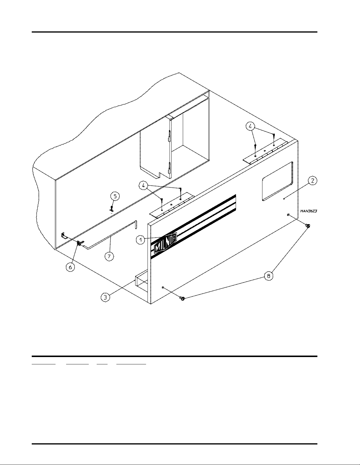
Control Door Assembly
Illus. No. Part No. Qty. Description
1 112366 1 Logo ONLY
2 881691 1 Control Door
(includes illus. nos. 2, 3, and 8)
3 117604 4 Neoprene Sponge Tape (sold by the foot)
4 150309 4 #10-16 x 1/2” Hex Head TEK Crimptite Screw
5 102603 1 Control Door Rod Support Catch
6 102601 1 Control Door Retainer Clip
7 102502 1 Control Door Rod
8 882541 2 Spring Turn Latch (2-piece)
Page 5
Telephone: (508) 678-9000
Fax: (508) 678-9447
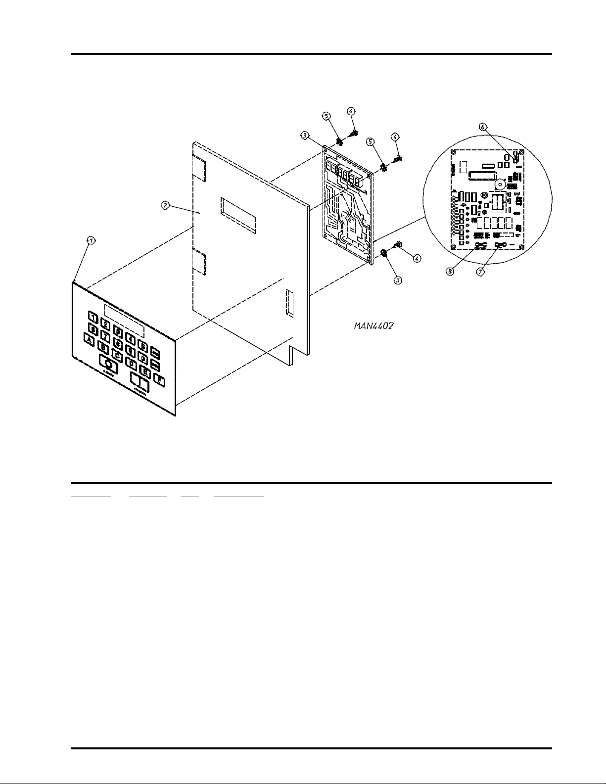
Phase 6 OPL Microprocessor Control Panel Assembly
3
Illus. No. Part No. Qty. Description
1 112537 1 Phase 6 OPL Keyboard
112276 1 OPL Stick- On Labels (English Only) ... Not Illustrated
112275 1 OPL Stick- On Labels
(Spanish, Italian, and Hebrew) ... Not Illustrated
112277 1 OPL Stick- On Labels
(English, Spanish, and Hebrew) ... Not Illustrated
112278 1 OPL Stick- On Labels
(Italian, Dutch, French, German, and Chinese) ... Not Illustrated
2 881745 1 Phase 6 Microprocessor Controller (computer) Panel ONLY
881746 1 Phase 6 OPL Reversing Microprocessor Controller (computer)
Control Panel Assembly Complete
(includes illus. nos. 1 through 8)
3 137122 1 Phase 6 OPL Reversing Microprocessor Controller (computer) ONLY
4 150005 2 #6-32 x 3/4” Phillips Round Head Machine Screw
5 153010 2 #6 Star Washer
6 136048 1 1/8-Amp (slo blo) Fuse ONLY
7 136017 1 3.15-Amp (fast acting) Fuse ONLY
8 136019 1 1-Amp (fast acting) Fuse ONLY
Page 6
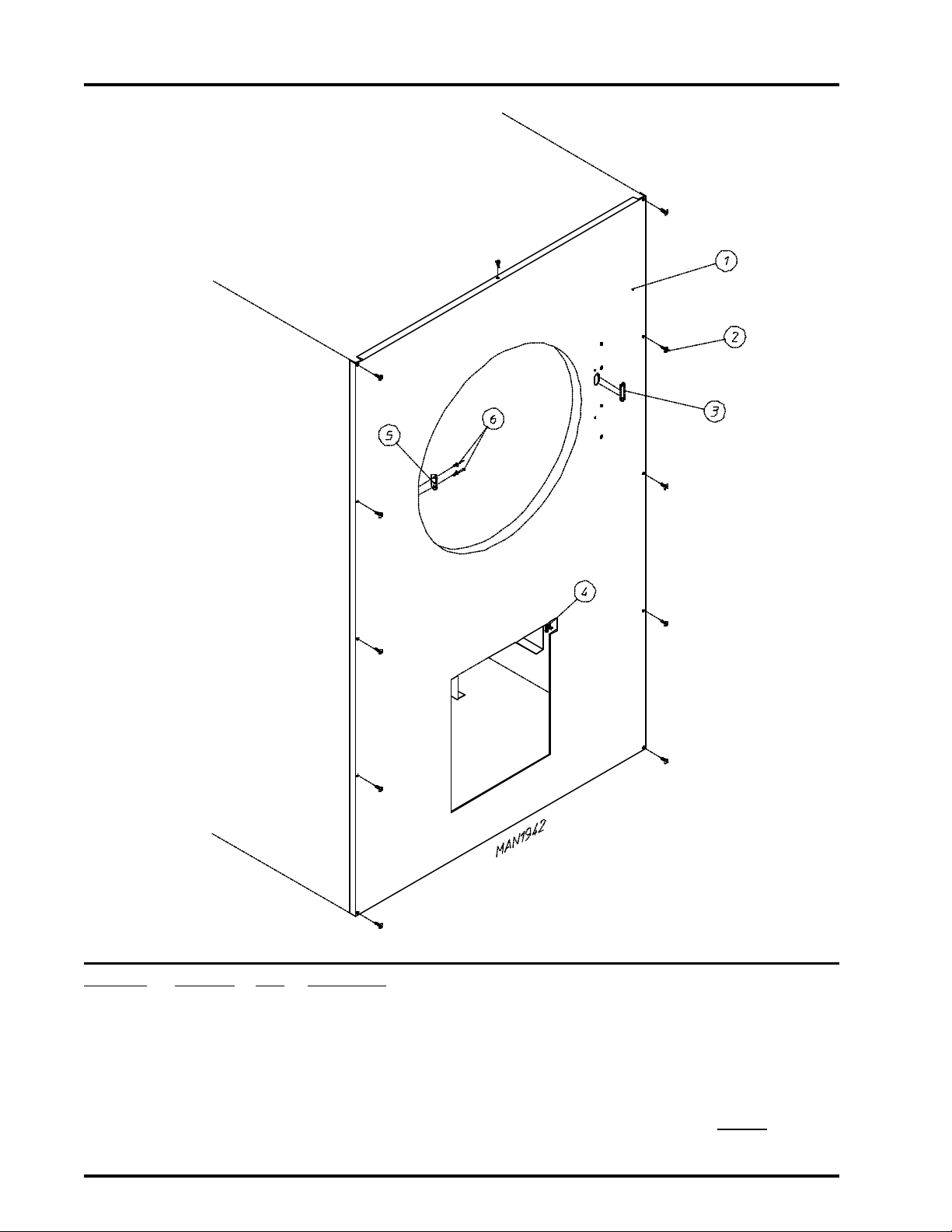
4
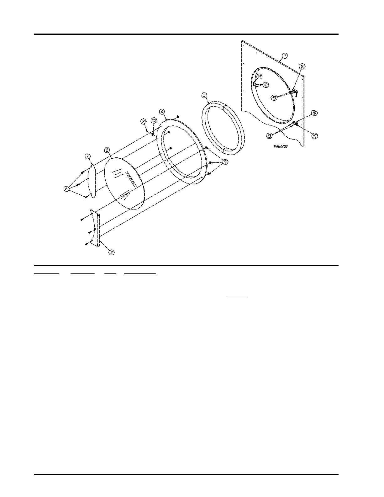
Front Panel/Main Door Assemblies
Illus. No. Part No. Qty. Description
1 -------- 1 Front Panel
(refer to Front Panel Assembly on page 6
2 102214 1 30” Door Glass ONLY
170730 1 Door/Glass Adhesive (10.3 oz. cartridge)
3 102357 1 Main Door Gasket ONLY (7/8” x 7/8” x 104”)
4 835003 1 Main Door Assembly Complete
(includes illus. nos. 2 through 10)
835002 1 Main Door Ring
5 881806 6 Free Spin Wash Nut
6 881740 6 1/4-20 x 5/8” Carriage Bolt
7 881688 1 CRS Main Door Handle
8 881685 1 Main Door Hinge
9 150120 1 Main Door Latch Screw
(#10-32 x 7/16” dome hex head screw)
10 152008 1 #10-32 Hex Nut
11 170330 1 Friction Door Catch
12 154215 2 5/32” Pop Rivet
13 150443 4 1/4-20 x 3/4” Stainless Steel Cap Screw
14 881440 1 Top Hinge Block (white)
(includes illus. nos. 13 and 14)
15 881441 1 Bottom Hinge Block (white)
(includes illus. nos. 13, 15, and 16)
16 153031 1 Nylon Washer
)
Page 7
Telephone: (508) 678-9000
Fax: (508) 678-9447
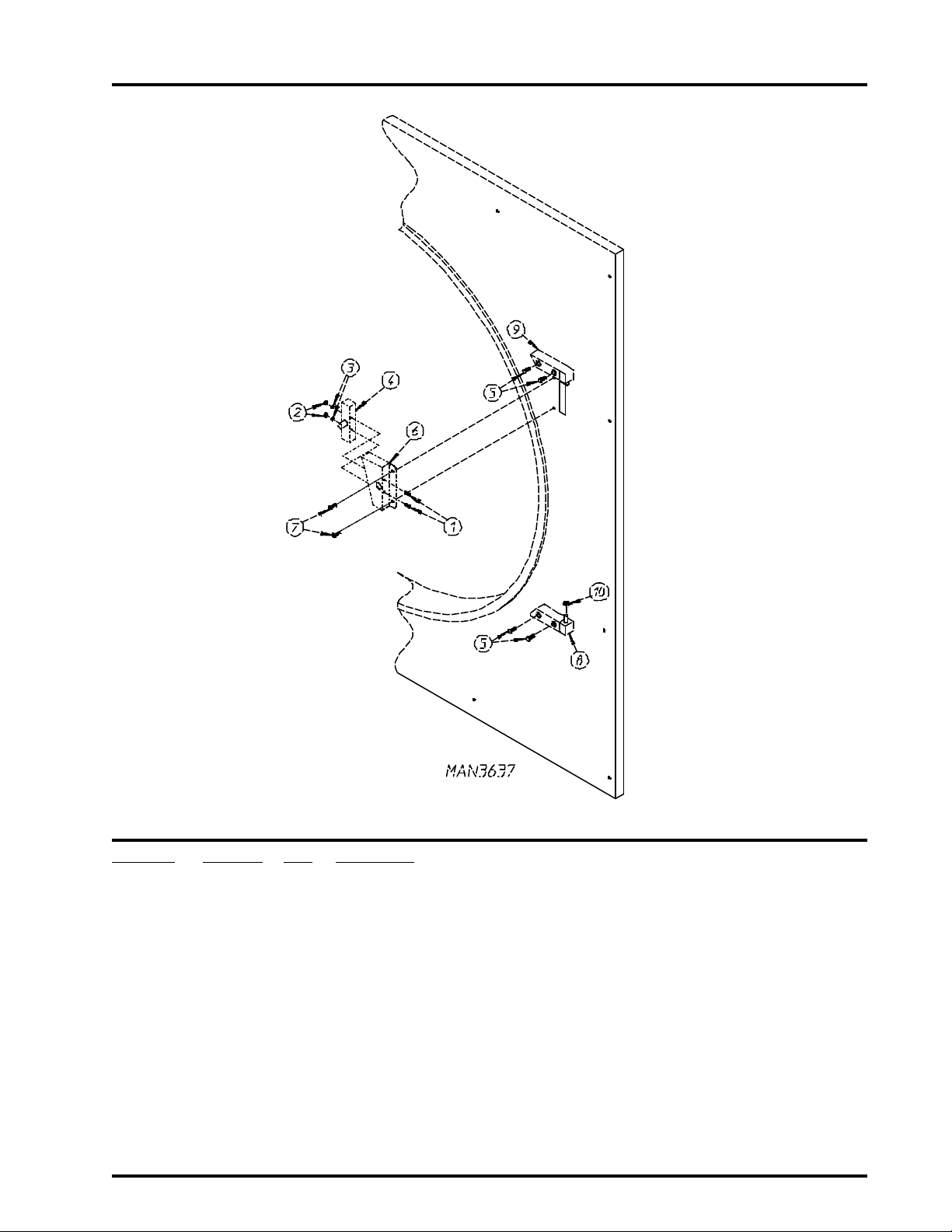
Main Door Switch Assembly
5
Illus. No. Part No. Qty. Description
1 150006 2 #6-32 x 7/8” Phillips Pan Head Machine Screw
2 152013 2 #6-32 Hex Nut
3 153010 2 #6 Star Washer
4 137005 1 Single Pole Door Switch
5 150443 4 1/4-20 x 3/4” Stainless Steel Cap Screw
6 881687 1 Main Door Switch Housing ONLY
7 150301 2 #8-18 x 7/16” Phillips Pan Head TEK Screw
8 881441 1 Bottom Hinge Block (white)
9 881440 1 Top Hinge Block (white)
10 153031 1 Nylon Washer
881702 1 Main Door Switch with Housing Assembly
(includes illus. nos. 1 through 4 and 6)
(includes illus. nos. 5, 8, and 10)
(includes illus. nos. 5 and 9)
Page 8
6
Front Panel Assembly
Illus. No. Part No. Qty. Description
1 851054 1 Front Panel Assembly
(includes illus. nos. 1, 3, 5, and 6)
2 150309 9 #10-16 x 1/2” Hex Head TEK Crimptite Screw
3 121405 1 Rubber Grommet
4 -------- 1 Lint Drawer Switch
(refer to Lint Drawer/Lint Drawer Switch Assembly on page 7
5 170330 1 Friction Door Latch
6 154215 2 5/32” Pop Rivet
)
Page 9

Telephone: (508) 678-9000
Fax: (508) 678-9447
Lint Drawer/Lint Drawer Switch Assembly
7
Illus. No. Part No. Qty. Description
1 881463 1 Lint Drawer Assembly
2 117605 5 Neoprene Sponge Gasket (sold by the foot)
3 802205 1 Lint Screen Assembly
4 122116 1 Lint Drawer Switch
5 122605 2 4-Pin Socket Connector
6 122701 4 Socket Terminal ONLY
7 835073 1 Lint Drawer Switch Box Assembly
8 152000 1 #6-32 Hex Nut
9 122700 4 Pin Terminal ONLY
10 122604 2 4-Pin Connector ONLY
(includes illus. nos. 1 and 2 Only)
835078 1 Lint Drawer Switch Harness ... Not Illustrated
122801 1 Socket Terminal Extraction Tool
(includes illus. nos. 4 through 8)
304136 1 Lint Switch Cover ONLY
Page 10

8
Basket (Tumbler)/Support Assemblies
Illus. No. Part No. Qty. Description
1 881780 1 Basket (tumbler) ONLY
881782 1 1-3/4” Reversing Basket (tumbler)/Support Assembly Complete
(includes illus. nos 1 through 12)
2 150413 40 #10-16 x 1/2” TORX Head Crimptite Screw
150429 1 TORX Hand Driver
(for removal of TORX head screw)
3 390074 4 Basket (tumbler) Rib ONLY
4 153002 1 5/16” Lock Washer
5 150500 1 5/16-18 x 3/4” Socket Button Head Screw
6 881779 1 Basket (tumbler) Support ONLY
7 116000 1 Felt Collar ONLY
401010 1 #847 Adhesive For Felt Collar (5 oz. tube)
8 153004 4 3/8” Flat Washer
9 100905 4 3/8-16 x 37” Tie Rod
10 152005 4 3/8-16 Hex Nut
11 153005 4 3/8” Lock Washer
12 153004 4 3/8” Flat Washer
Page 11

Telephone: (508) 678-9000
Fax: (508) 678-9447
Sensor Bracket Assembly
9
Illus. No. Part No. Qty. Description
1 880251 1 1/4” Temperature Sensor Probe Assembly
2 122605 1 4-Pin Socket Connector ONLY
3 122701 4 Socket Terminal ONLY
4 154007 2 1/4” Tinnerman Push On Fastener
5 150000 2 #6-32 x 1/4” Round Head Machine Screw
6 802174 1 Sensor Bracket Assembly Complete
7 130301 1 225° Large Manual Reset Thermostat
8 153010 2 #6 Star Washer
9 152000 2 #6-32 Hex Nut
10 150301 2 #8-18 x 7/16” Phillips Pan Head TEK Screw
11 122604 1 4-Pin Connector ONLY
12 122700 4 Pin Terminal ONLY
--- 122801 1 Pin/Extraction Tool
(includes illus. nos. 1 through 4)
(includes illus. nos. 1 through 9)
323626 1 Temperature Sensor Bracket ONLY
Page 12

10
Tumbler Bearing Assembly
Page 13

Telephone: (508) 678-9000
Fax: (508) 678-9447
Tumbler Bearing Assembly
Illus. No. Part No. Qty. Description
1 880220 1 1-3/4” Flange Bearing
2 153025 4 9/16” Lock Washer
3 152050 4 9/16-12 Hex Nut
4 150508 2 3/8-16 x 3/4” Hex Head Machine Bolt
5 153005 4 3/8” Lock Washer
6 152005 2 3/8-16 Hex Nut
7 150600 2 3/8-16 x 1-1/2” Hex Head Machine Bolt
8* 153004 6 3/8” Flat Washer
9 153005 2 3/8” Lock Washer
10 152005 4 3/8-16 Hex Nut
11 150501 4 5/16-18 x 3/4” Hex Head Machine Bolt
12 153002 4 5/16” Lock Washer
13 153001 4 5/16” Flat Washer
14 150621 2 5/16-18 x 1-1/2” Hex Head Machine Bolt
15 152004 2 5/16-18 Hex Nut
16 801107 1 1-3/8” Bearing Box Assembly Complete with Rotational Sensor Assembly
(includes illus. nos. 4 through 20 and 25)
801103 1 1-3/8” Bearing Box and Support ONLY
(includes illus. nos. 4 through 6, 16, and 17)
801105 1 1-3/8” Bearing Box ONLY
17 801104 1 Pillow Block Bearing Support ONLY
18 880779 1 1-3/8” Pillow Block Bearing Assembly with Magnet
19 152004 4 5/16-18 Hex Nut
20 150610 2 5/16-18 x 1-1/2” Allen Set Screw
21 101118 1 18-3/4” Pulley
22 101119 1 1-3/8” Taper Lock Hub (key is not included)
23 100735 1 Shaft Key
(for taper lock hub)
24 100106 1 5L-690 V-Belt (to idler assembly)
25 824807 1 Rotational Sensor Assembly
11
* Some models require a quantity of 4.
Page 14

12
Idler Bearing Assembly
Illus. No. Part No. Qty. Description
1 100106 1 5L-690 V-Belt (basket [tumbler] to idler)
2 101140 1 14” x 3” Compound Pulley
3 100158 1 4L-550 V-Belt (idler to motor)
4 154301 2 5/16-18 x 1” Allen Set Screw
5 100705 1 3/16” x 3/16” x 1-3/8” Key
6 801007 1 Idler Bearing Assembly Complete
(includes illus. nos. 5 through 12)
7 150617 2 3/8-16 x 1” Hex Head Machine Bolt
8 153005 2 3/8” Lock Washer
9 153004 2 3/8” Flat Washer
10 801009 1 Idler Square Washer
11 152004 1 5/16-18 Hex Nut
12 150509 1 5/16-18 x 3” Hex Head Machine Bolt
Page 15

Telephone: (508) 678-9000
Fax: (508) 678-9447
Blower Motor Assembly
13
Illus. No. Part No. Qty. Description
1* 100169 1 5L-350 V-Belt (fan shaft to motor)
2 100704 1 1/4” x 1/4” x 1-3/4” Key
3 101138 1 SDS x 1-1/8” Bushing
4 101202 1 2B x 5.2 Pulley
5** 100043 1 3 HP Motor
6 152004 4 3/8-16 Hex Nut
7 153002 4 3/8” Lock Washer
8 153001 4 3/8” Flat Washer
9 802253 1 Adjustment Plate
10 802232 1 Adjustment Angle
11 152034 2 3/8-16 x 3-1/2” Bolt
12 152005 4 3/8-16 Hex Nut
13 150501 4 5/16-18 x 3/4” Bolt
14 153005 4 3/8” Lock Washer
15 153004 4 3/8” Flat Washer
* Replace in matched sets (both belts).
** Check part number on motor data label to verify correct motor.
Page 16

14
Totally Enclosed, Fan-Cooled (T.E.F.C.) Drive Motor/Fan Shaft Motor Mount Assemblies
Page 17

Telephone: (508) 678-9000
Fax: (508) 678-9447
Totally Enclosed, Fan-Cooled (T.E.F.C.) Drive Motor/Fan Shaft Motor Mount Assemblies
Illus. No. Part No. Qty. Description
1 100158 1 4L-550 V-Belt (motor to idler)
2 101130 1 5/8” x 2-1/2” Motor Pulley
3* 181003 1 1/2 HP 3ø Totally Enclosed, Fan-Cooled (T.E.F.C.) Motor
4 150501 4 5/16-18 x 3/4” Machine Bolt
5 153002 4 5/16” Lock Washer
6 153001 4 5/16” Flat Washer
7 100706 1 5/16” x 5/16” x 1-3/8” Key
8 101194 1 SDS x 1-3/8” Bushing
9 101147 1 2B x 4.8 Pulley
10** 100169 1 5L-350 V-Belt (fan shaft to motor)
11 317400 1 Impellor/Fan Shaft
12 153004 4 3/8” Flat Washer
13 153005 4 3/8” Lock Washer
14 150600 4 3/8-16 x 1-1/2” Machine Bolt
15 880879 2 1-3/8” Pillow Block Bearing with Set Screw and Grease Fitting
16 116014 1 3” x 3” Fan Shaft Gasket
17 802231 1 Fan Shaft Motor Mount ONLY
18 117604 5 Neoprene Sponge Tape (sold by the foot)
19 100603 1 16” Cast Impellor (fan)
20 153050 1 1/2” Flat Washer
21 152006 2 1/2-20 Left Hand Jam Nut
15
* Check part number on motor data label to verify correct motor.
** Replace in matched sets (both belts).
Page 18

16
Direct Spark Ignition (DSI) Burner Assembly
Page 19

Telephone: (508) 678-9000
Fax: (508) 678-9447
Direct Spark Ignition (DSI) Burner Assembly
Illus. No. Part No. Qty. Description
1* 803020 1 Natural Gas Burner Assembly Complete
(includes illus. nos. 1 through 29)
803021 1 Liquid Propane (L.P.) Burner Assembly Complete
(includes illus. nos 1 through 29)
802237 1 Burner Box ONLY
2 802240 1 Direct Spark Ignition (DSI) Burner Shield (4-tube burner)
3 150309 15 #10-16 x 1/2” Hex Head TEK Crimptite Screw
4 128915 1 Direct Spark Ignition (DSI) Ignitor/Flame-Probe Assembly
5 150300 2 #10 x 1/2” Hex Washer TEK Screw
6 141105 4 Large Burner Tube
7 150103 4 #8-32 x 1/2” Pan Head Machine Screw
8 153000 4 #8 Steel Burr
9 151001 4 #8-32 Pal Nut
10* 140856 4 #23 Burner Orifice (natural gas Only)
140811 4 #41 Burner Orifice (liquid propane [L.P.] gas Only)
11 141210 1 3/4” Direct Spark Ignition (DSI) Manifold (4-port)
12 323737 2 Pipe Bracket (bent)
13 128928 1 1/2” 24 VAC Redundant (natural gas) Valve
881052 1 1/2” 24 VAC Redundant (liquid propane [L.P.] gas) Valve
882119 1 1/2” 24 VAC Redundant Liquid Propane (L.P.) Conversion Kit
14 142715 1 1/2” x 2” Nipple
15 142511 1 3/4” x 1/2” Reducing Elbow
16 142721 1 3/4” x 28” Pipe
17 323763 1 Gas Valve Bracket
18 824533 1 Hi-Limit Harness
19 319704 1 Hi-Limit Mounting Bracket
20 151000 2 #6-32 Pal Nut
21 151001 2 #6-32 x 1/2” Round Head Machine Screw
22 130201 1 330° Hi-Limit Manual Reset
23 -------- 1 Sail Switch
(refer to Sail Switch Assembly on page 20)
24 810030 1 Johnson Controls Direct Spark Ignition (DSI) Module Mounting Bracket
25 128935 1 Direct Spark Ignition (DSI) Module with Three Tries
26 142601 1 3/4” Union
27 142924 1 1” to 3/4” Reducing Coupling
28 152013 2 #6-32 Hex Nut 1/4” ATF Zinc Plated
29 142701 1 3/4” Close Nipple
17
* Consult factory for elevations over 2,000 feet.
Page 20

18
Hot Surface Ignition (HSI) Burner Assembly
Illus. No. Part No. Qty. Description
1 802237 1 Burner Box ONLY
881258* 1 Natural Gas Burner Assembly Complete Less Orifices
(includes illus. nos. 1 through 9 and 11 through 30)
881257* 1 Liquid Propane (L.P.) Burner Assembly II Complete Less Orifice
(includes illus. nos. 1 through 9 and 11 through 30)
2 318041 1 Burner Shield
3 150309 17 #10-16 x 1/2” Hex Head TEK Crimptite Screw
Page 21

Telephone: (508) 678-9000
Fax: (508) 678-9447
Hot Surface Ignition (HSI) Burner Assembly (continued)
Illus. No. Part No. Qty. Description
4 881597 1 Hot Surface Ignitor - 24 VAC
5 128921 1 Hot Surface Ignition (HSI) Flame-Probe
6 141105 4 Large Burner Tube
7 150103 4 #8-32 x 1/2” Phillips Pan Head Machine Screw
8 153000 4 #8 Steel Bar
9 151001 6 #8-32 Pal Nut
10** 140856 4 #23 Burner Orifice (natural gas) ONLY
140811 4 #41 Burner Orifice (liquid propane [L.P.]) ONLY
11 141210 1 3/4” Manifold (4-port)
12 323769 2 Pipe Bracket (bent)
13 128928 1 1/2” 24 VAC Redundant (natural gas) Gas Valve
881052 1 1/2” 24 VAC Redundant (liquid propane [L.P.]) Gas Valve
882119** 1 Hot Surface Ignition (HSI) liquid propane (L.P. ) Conversion Kit
14 142715 2 1/2” x 1/2” Nipple
15 142511 1 3/4” x 1/2” Reducing Elbow
16 142829 1 3/4” x 20” Pipe
17 323763 1 Gas Valve Bracket
18 842891 1 Sail Switch to Hi-Limit Harness
19 319704 1 Hi-Limit Mounting Bracket
20 151000 2 #6-32 Pal Nut
21 151001 2 #6-32 x 1/2” Round Head Machine Screw
22 130201 1 330º Manual Reset Hi-Limit Thermostat ONLY
23 -------- 1 Sail Switch
(refer to Sail Switch Assembly on page 20)
24 141300 1 3/4” Union Shutoff
25 142709 2 3/4” x 2” Nipple
26 142601 1 3/4” Union
27 142924 1 1” to 3/4” Reducing Coupling
28 810029 1 Hot Surface Ignition (HSI) Mounting Bracket Assembly
29 881797 1 Hot Surface Ignition (HSI) Module II
30 150301 1 #8-18 x 7/16” Phillips Pan Head TEK Screw
19
* Burner orifices are not included and must be ordered separately.
** Consult factory for elevations over 2,000 feet.
Page 22

20
Sail Switch Assembly
Illus. No. Part No. Qty. Description
1 105500 1 Sail Switch Actuator Rod
2 319202 1 Sail Switch Damper (flat)
3 154002 1 1/8” Push On Fastener
4 802800 1 Sail Switch Box with Cover and Bracket ONLY
(includes illus. nos. 4, 8, and 9)
802801 1 Sail Switch Box Assembly Complete
(includes illus. nos. 1 through 4 and 6 through 10)
5 150309 2 #10-16 x 1/2” Hex Head TEK Crimptite Screw
6 150303 2 #4 x 3/4” Pan Head “A” Machine Screw
7 122200 1 Sail Switch ONLY
8 802799 1 Sail Switch Box Cover and Bracket ONLY
9 150309 2 #10-16 x 1/2” Hex Head TEK Crimptite Screw
10 154004 1 Twin Speed Nut
Page 23

Telephone: (508) 678-9000
Fax: (508) 678-9447
Reversing Relay Panel Assembly
21
Illus. No. Part No. Qty. Description
1 132467 1 9-13-Amp Overload (208-240 Volt)
2 132445 1 24 VAC 3-Phase (3ø) Contactor
3 150300 2 #10-16 x 1/2” Hex Washer TEK Screw
4 150008 2 #6-32 x 1-1/4” Phillips Round Head Machine Screw
5 120701 1 4-Position Terminal Block
6 132448 1 Reversing Contactor
7 842894 1 208-240 Volt Transformer Assembly
8 137060 1 Arc Suppressor (A.S.) Board
9 137013 4 Nylon Standoff
10 151000 2 #6-32 Pal Nut
11 152004 1 5/16-18 Pal Nut
12 121010 1 L-70 Ground Lug
13 153002 1 5/16” Lock Washer
14 136008 2 Fuse Holder ONLY
15 136057 2 0.5-Amp (slo blo) Fuse ONLY
16 323743 1 Relay Panel ONLY
835074 1 Reversing Relay Panel Assembly Complete
(includes illus. nos. 1 through 18)
17 150301 2 #8-18 x 7/16” Phillips Pan Head TEK Screw
18 150297 1 #10 x 1/2” Hex Washer TEK Screw (green)
Page 24

22
Outer Top/Back Guard Assemblies
Illus. No. Part No. Qty. Description
1 312527 1 Outer Top Assembly
2 150301 8 #8-18 x 7/16 Phillips Pan Head TEK Screw
3 323759 1 Top Back Guard Assembly (26-7/8” x 13-15/16”)
4 150301 6 #8-18 x 7/16” Phillips Pan Head TEK Screw
5 323749 1 Rear Electrical Box Cover (10-13/16” x 9-3/4”)
6 150301 6 #8-18 x 7/16” Phillips Pan Head TEK Screw
7 314511 1 Lower Back Guard
8 150301 10 #8-18 x 7/16” Phillips Pan Head TEK Screw
9 103500 4 Leveling Leg
10 882203 1 12” to 14” Exhaust Damper Increaser
11 112519 1 “Routine Maintenance Schedule” Label
12 114092 1 “Exhaust Transition Warning” Label
Page 25

Telephone: (508) 678-9000
Fax: (508) 678-9447
Additional Parts Available
Part No. Description
112075 “Ground Here” Label
112280 “Clean Lint Screen” Label
112804 Manometer (hydro gauge) For Measuring Gas Pressure
112284 “Phase 6 OPL Program Location Summary” Label
114001 “CAUTION - Exhaust/Lint Screen” Label
114006 “WARNING - Fire Hazards” Label
114051 “Phase A - B Factor” Label
117505 Aluminum Duct Tape (sold by the foot)
120100 3/8” Straight (BX) Connector
120301 1/2” x 45° (BX) Connector
120400 3/8” Red Jacket (BX) Insulator
120500 3/8” Jiffy Clip (BX Retainer Clip)
120600 3/8” Greenfield (BX)
120800 1/4” In-Line Connector
120802 Red Butt Connector
120902 #74B Wire Nut
120903 Crimp-On Wire Nut
121014 1/4” Insulated (female) Terminal
121499 4” Harness Tie
121500 7” Harness Tie
121503 Harness Tie Mounting Clip
404502 White Brush-In-Cap Bottle Touch-Up Paint
880884 Tumbler Bearing Puller
404507 Cornflower Blue Brush-In-Cap Bottle Touch-Up Paint
404513 Wrinkle Blue Brush-In-Cap Bottle Touch-Up Paint
23
Page 26

ADC 450403 1- 04/13/99-50 2- 02/25/00-25 3- 05/12/00-35
4* 09/11/00-25
 Loading...