

Page 1
ML-55 Parts Manual
Phase 7 / OPL / Dual Timer
with F.S.S. Options
American Dryer Corporation
88 Currant Road
Fall River, MA 02720-4781
Telephone: (508) 678-9000 / Fax: (508) 678-9447
E-mail: techsupport@amdry.com
www.amdry.com
ADC Part No. 450564-3
Page 2

Retain This Manual In A Safe Place For Future Reference
American Dryer Corporation products embody advanced concepts in engineering, design, and safety . If this product
is properly maintained, it will provide many years of safe, efficient, and trouble free operation.
ONL Y qualified technicians should service this equipment.
OBSERVE ALL SAFETY PRECAUTIONS displayed on the equipment or specified in the installation manual included
with the dryer.
The following “FOR YOUR SAFETY” caution must be posted near the dryer in a prominent location.
FOR YOUR SAFETY
Do not store or use gasoline or
other flammable vapors and
liquids in the vicinity of this or
any other appliance.
We have tried to make this manual as complete as possible and hope you will find it useful. ADC reserves the right to
make changes from time to time, without notice or obligation, in prices, specifications, colors, and material, and to
change or discontinue models.
Ne pas entreposer ni utiliser d’essence
ni d’autres vapeurs ou liquides
inflammables à proximité de cet appareil
ou de tout autre appareil.
POUR VOTRE SÉCURITÉ
Important
For your convenience, log the following information:
DATE OF PURCHASE ____________________________________________________ MODEL NO. ______________
RESELLER’S NAME _________________________________________________________________________________
Serial Number(s)_____________________________________________________________________________________
ML-55
____________________________________________________________________________________________________
____________________________________________________________________________________________________
Replacement parts can be obtained from your reseller or the ADC factory . When ordering replacement part s from the
factory , you can FAX your order to ADC at (508) 678-9447 or telephone your order directly to the ADC Parts Department
at (508) 678-9000. Please specify the dryer model number and serial number in addition to the description and part
number, so that your order is processed accurately and promptly.
The illustrations on the following pages may not depict your particular dryer exactly . The illustrations are a composite
of the various dryer models. Be sure to check the descriptions of the parts thoroughly before ordering.
“IMPORT ANT NOTE T O PURCHASER”
Information must be obtained from your local gas supplier on the
instructions to be followed if the user smells gas. These
instructions must be posted in a prominent location near the dryer.
Page 3

Table of Contents
Phase 7 OPL Microprocessor Control Door Assembly for Models Mfd. as of July 11, 2002 ......................................4
Dual Timer OPL Control Door Assembly for Models Mfd. as of July 11, 2002............................................................5
Phase 7 Microprocessor Control Door Assembly for Models Mfd. prior to July 11, 2002 ...........................................6
Dual Timer Control Door Assembly for Models Mfd. prior to July 11, 2002 ................................................................7
Phase 7 OPL Microprocessor Control Panel Assembly .............................................................................................8
Dual Timer “Tap Touch” Controls................................................................................................................................9
Phase 7 OPL Microprocessor Control Box Assembly ..............................................................................................10
Dual Timer Control Box Assembly............................................................................................................................11
Front Panel / Main Door Assemblies with Mechanical Fasteners.............................................................................12
Main Door Switch Assembly.....................................................................................................................................14
Drop Lint Door Assembly..........................................................................................................................................15
Sensor Bracket Assemblies .....................................................................................................................................16
Lint Trap Assembly...................................................................................................................................................18
Tumbler / Support Assemblies .................................................................................................................................19
Tumbler Bearing Assembly ......................................................................................................................................20
Non-Reversing T.E.F.C. Motor Mount Assembly ......................................................................................................22
Reversing T.E.F.C. Motor Mount Assembly ..............................................................................................................24
Direct Sp ark Ignition Burner Assembly .....................................................................................................................26
Hot Surface Ignition Burner Assembly......................................................................................................................28
Idler Bearing Assembly.............................................................................................................................................30
Sail Switch / Hi-Limit Assemblies .............................................................................................................................31
Air-Operated Steam Damper Assembly ............................................................................................. ......................32
Electric Oven Assembly............................................................................................................................................34
Single-Phase (1ø) MP Rear Electric Relay Panel Assembly....................................................................................36
208-240V 3-Phase (3ø) MP Rear Electric Relay Panel Assembly ...........................................................................37
480V MP Rear Electric Relay Panel Assembly.........................................................................................................38
208-240V MP Reversing Rear Electric Relay Panel Assembly ................................................................................39
460-480V MP Reversing Rear Electric Relay Panel Assembly ................................................................................40
Single-Phase (1ø) Dual Timer Rear Electric Relay Panel Assembly................................................................ ........41
3-Phase (3ø) 208-240V Dual Timer Rear Electric Relay Panel Assembly for Gas Models Only..............................42
460-480V Dual Timer Rear Electric Relay Panel Assembly for Gas Models Only....................................................43
208-240V Dual Timer Reversing Rear Electric Relay Panel Assembly for Gas Models Only ..................................44
F.S.S. T emperature Probe Assembly.............................................................................................. ..........................45
F .S.S. Solenoid Assembly ........................................................................................................................................46
Outer Top / Back Guard Assemblies ........................................................................................................................47
Step Down Transformer Usage Listing.....................................................................................................................48
Electric Oven Component Application Chart ............................................................................................................49
Additional Parts Available .........................................................................................................................................50
Page 4
Phase 7 OPL Microprocessor Control Door Assembly
For Models Mfd. as of July 11, 2002
Illus. No. Part No. Qty. Description
1 883698 1 White OPL Control Door
(includes illus. nos. 1 and 3)
2 150321 2 #10-32 x 1/2” Phillips Machine Screw
3 117604 4 Neoprene Sponge Tape (sold by the foot)
4 150317 2 #10-16 x 3/4” TORX PLUS
5 102502 1 Control Door Support Rod
6 154011 2 #10-32 Multi-Thread U-Nut
7 102603 1 Control Door Rod Support Latch
8 102601 1 Control Door Rod Retainer Clip
9 ––––––* 1 Logo ONLY
* Contact reseller for logo.
4 American Dryer Corporation 450564 -3
®
BTN Type 1
Page 5
Dual Timer OPL Control Door Assembly
For Models Mfd. as of July 11, 2002
Illus. No. Part No. Qty. Description
1 883697 1 White OPL Control Door
(includes illus. nos. 1 and 3)
2 150321 2 #10-32 x 1/2” Phillips Machine Screw
3 117604 4 Neoprene Sponge Tape (sold by the foot)
4 150317 2 #10-16 x 3/4” TORX PLUS
5 102502 1 Control Door Support Rod
6 154011 2 #10-32 Multi-Thread U-Nut
7 102603 1 Control Door Rod Support Latch
8 102601 1 Control Door Rod Retainer Clip
9 ––––––* 1 Logo ONLY
* Contact reseller for logo.
450564-3 www.amdry.com 5
®
BTN Type 1
Page 6
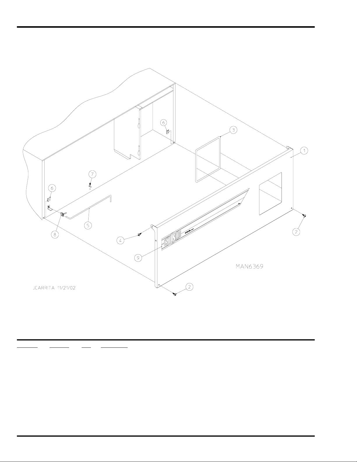
Phase 7 Microprocessor Control Door Assembly
For Models Mfd. prior to July 11, 2002
Illus. No. Part No. Qty. Description
1 824169 1 Control Door
(includes illus. nos. 1 and 2)
2 117604 2 1/8” x 3/8” Noise Tape
3 150314 4 #10-32 x 1/2” TORX
4 154011 4 #10-32 Multi-Thread U-Nut
5 112366 1 Milnor Logo
6 American Dryer Corporation 450564 -3
®
Screw
Page 7
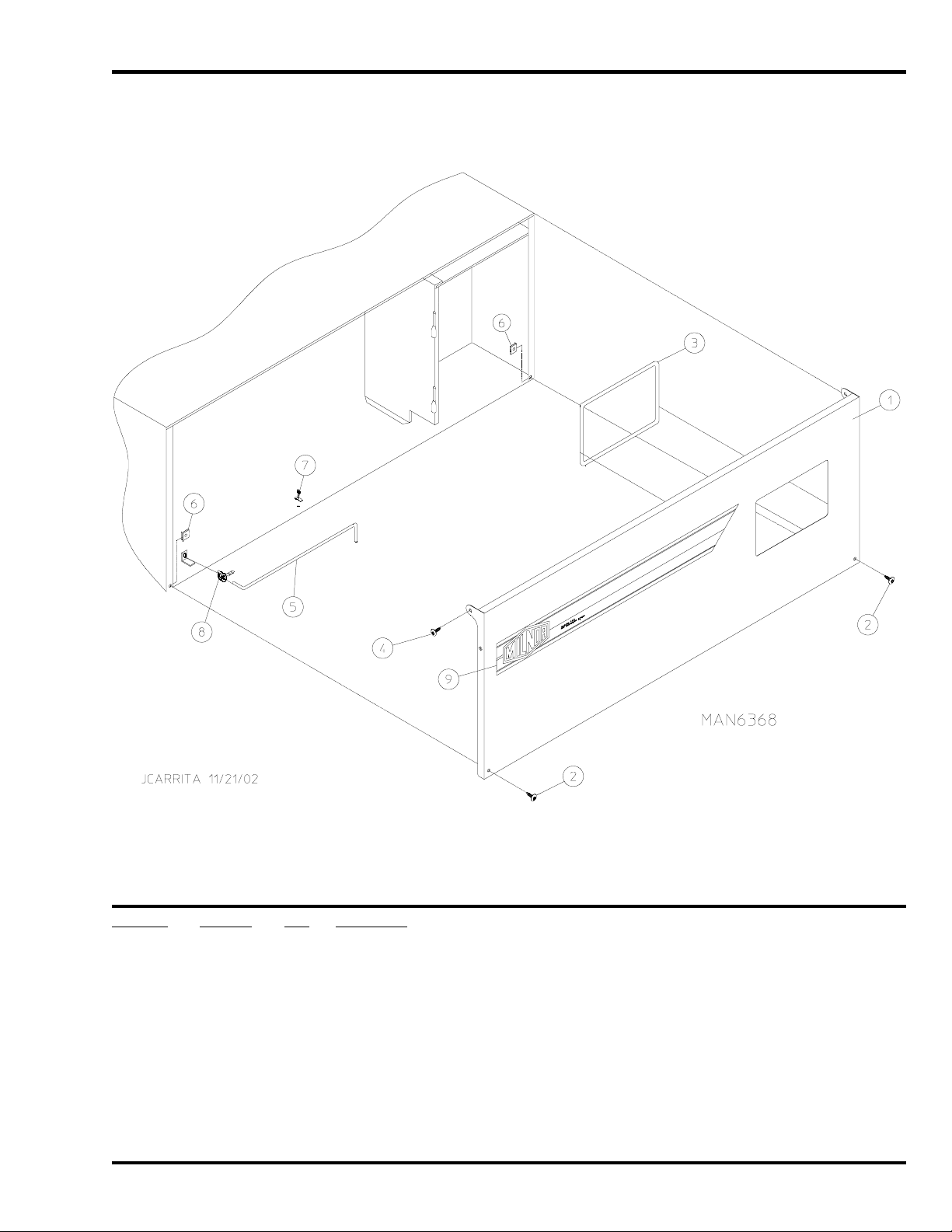
Dual Timer Control Door Assembly
For Models Mfd. prior to July 11, 2002
Illus. No. Part No. Qty. Description
1 ––––––* 1 Logo ONLY
2 881869 1 White Control Door Assembly
(for models mfd. as of October 24, 1997)
(includes illus. nos. 2, 3, and 8)
881744 1 White Control Door Assembly
(for models mfd. prior to October 24, 1997)
(includes illus. nos. 2, 3, and 8)
3 117604 4 Noise Suppression Tape (sold by the foot)
4 150309 4 #10-16 x 1/2” Hex Head TEK Crimptite Screw
5 102603 1 Control Door Rod Support Catch
6 102601 1 Control Door Rod Retainer Clip
7 102502 1 Control Door Support Rod
8 882541 2 Spring Turn Latch (2-piece)
* Contact reseller for logo.
450564-3 www.amdry.com 7
Page 8
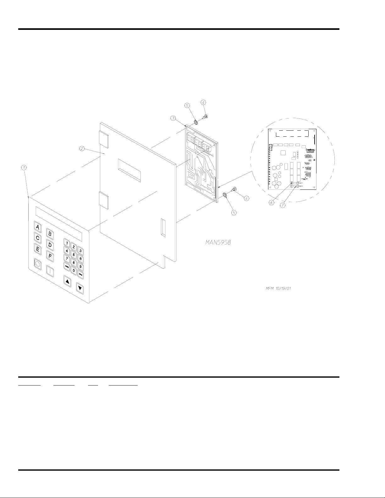
Phase 7 OPL Microprocessor Control Panel Assembly
Illus. No. Part No. Qty. Description
1 112571 1 Phase 7 OPL Keypad
2 850984 1 Phase 7 OPL Microprocessor Controller (computer) Panel ONLY
822767 1 Phase 7 OPL Reversing Microprocessor Controller (computer)
Control Panel Assembly Complete
(includes illus. nos. 1 through 7)
3 137247 1 Phase 7 OPL Microprocessor Controller (computer) ONLY
4 150005 2 #6-32 x 3/4” Phillips Round Head Machine Screw
5 153010 2 #6 Star Washer
6 136016 1 5-Amp Fuse
7 136097 1 500 mA Fuse
8 American Dryer Corporation 450564 -3
Page 9
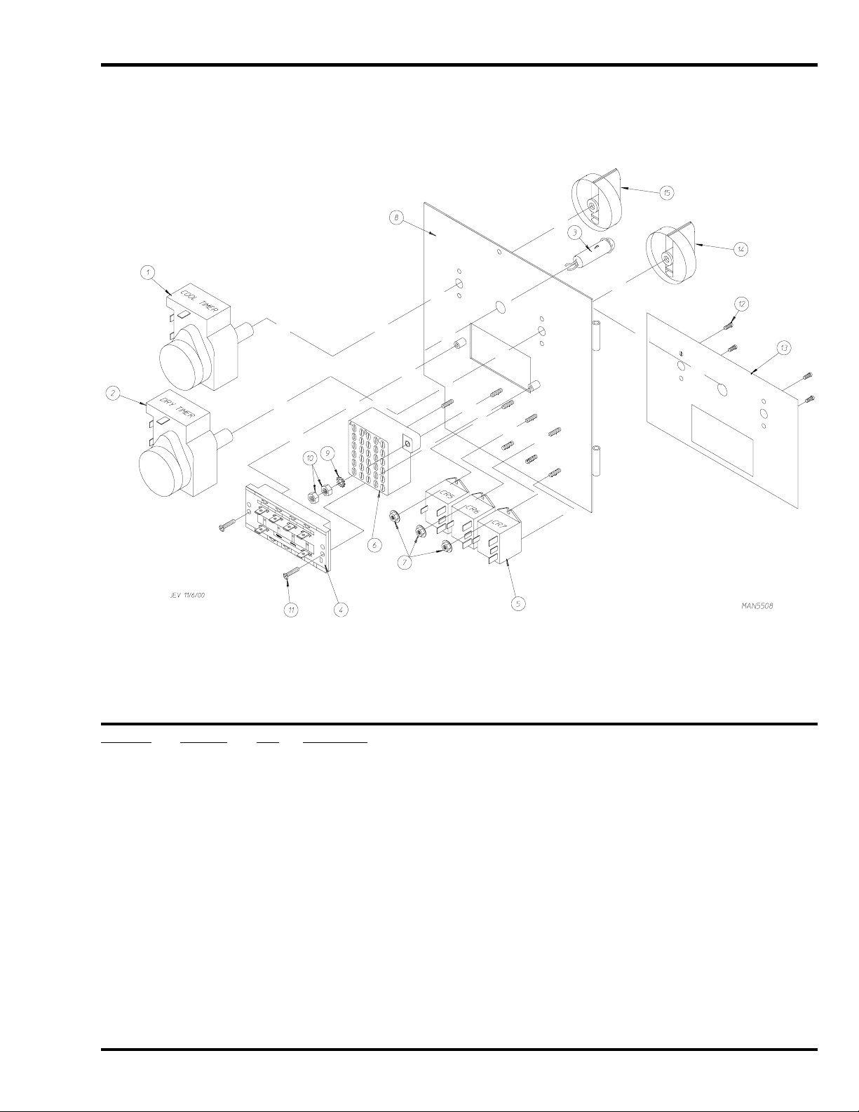
Dual Timer “Tap Touch” Controls
Illus. No. Part No. Qty. Description
1 124030 1 15 Minute Timer – 24 VAC
2 124025 1 60 Minute Timer – 24 VAC
3 824175 1 Red Pilot Light – 24 VAC
4 122301 1 “Tap Touch” Switch
5 131932 3 Relay SPST 24v
6 120730 1 30-Position Terminal Block
7 151000 6 #6-32 Pal Nut
8 882903 1 Dual Timer Panel Complete
(includes illus. nos. 1 through 15)
850392 1 Dual Timer Panel ONLY
9 153010 2 #6 Star Washer
10 152000 3 #6-32 Hex Nut
11 150207 2 #10-24 x 1/2” Phillips Pan Head Machine Screw
12 150110 4 #8-32 x 1/4” Phillips Round Head Machine Screw
13 112563 1 Dual Timer Panel Overlay
14 124104 1 Pure Touch Knob with Red Pointer
15 124105 1 Pure Touch Knob with Blue Pointer
450564-3 www.amdry.com 9
Page 10
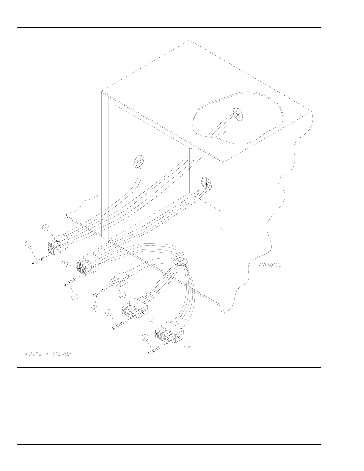
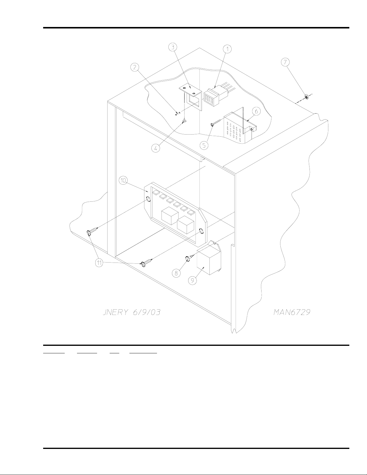
Phase 7 OPL Microprocessor Control Box Assembly
Illus. No. Part No. Qty. Description
1 122681 1 10-Pin Connector
2 122676 1 8-Pin Connector
3 122646 1 2-Pin Connector
4 122683 1 6-Pin Connector
5 122640 1 9-Pin Connector
6 122706 * #20-16 U.M.N.L. Socket
7 122669 * Female Crimp Terminal
* As needed.
10 American Dryer Corporation 450564 -3
Page 11
Dual Timer Control Box Assembly
Illus. No. Part No. Qty. Description
1 122601 1 9-Pin Connector
2 122701 8 Socket Terminal ONLY
122801 1 Pin / Socket Extraction Tool
3 315010 1 9-Pin Connector Bracket
4 150300 2 #10-16 x 1/2” Hex Washer TEK Screw
5 150002 2 #6-32 x 1” Phillips Round Head Machine Screw
6 120715 1 30-Position Terminal Block
7 151000 2 #6-32 Pal Nut
8 150300 2 #10-16 x 1/2” Hex Washer TEK Screw
9 131932 1 Heat Relay – 24 VAC (hot surface ignition models Only)
10 884252 1 Reversing Timer (for reversing models Only)
11 150301 1 #8-18 x 7/16” Phillips Pan Head TEK Screw
450564-3 www.amdry.com 11
Page 12
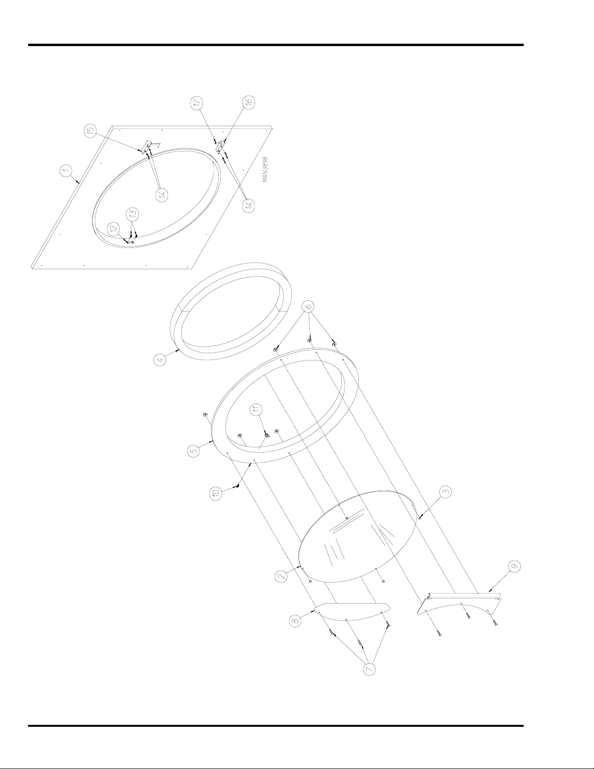
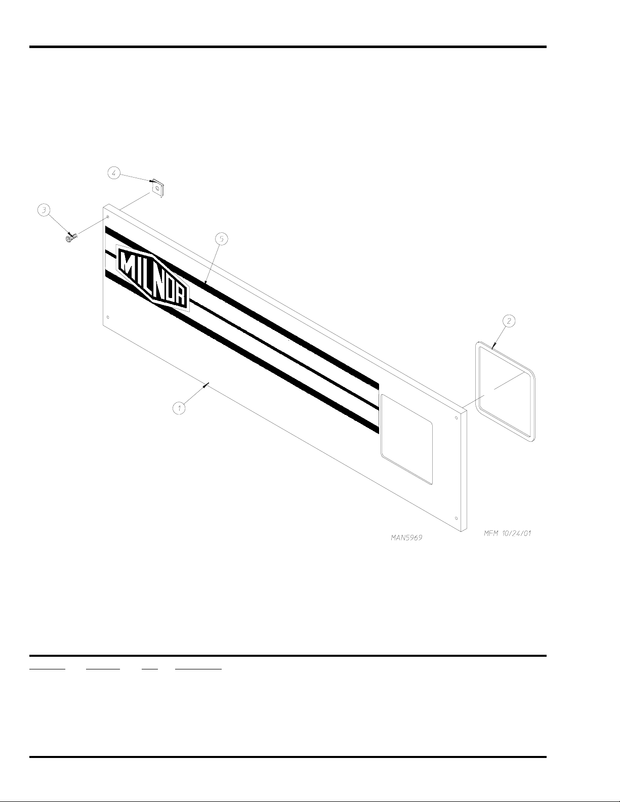
Front Panel / Main Door Assemblies with Mechanical Fasteners
12 American Dryer Corporation 450564 -3
Page 13

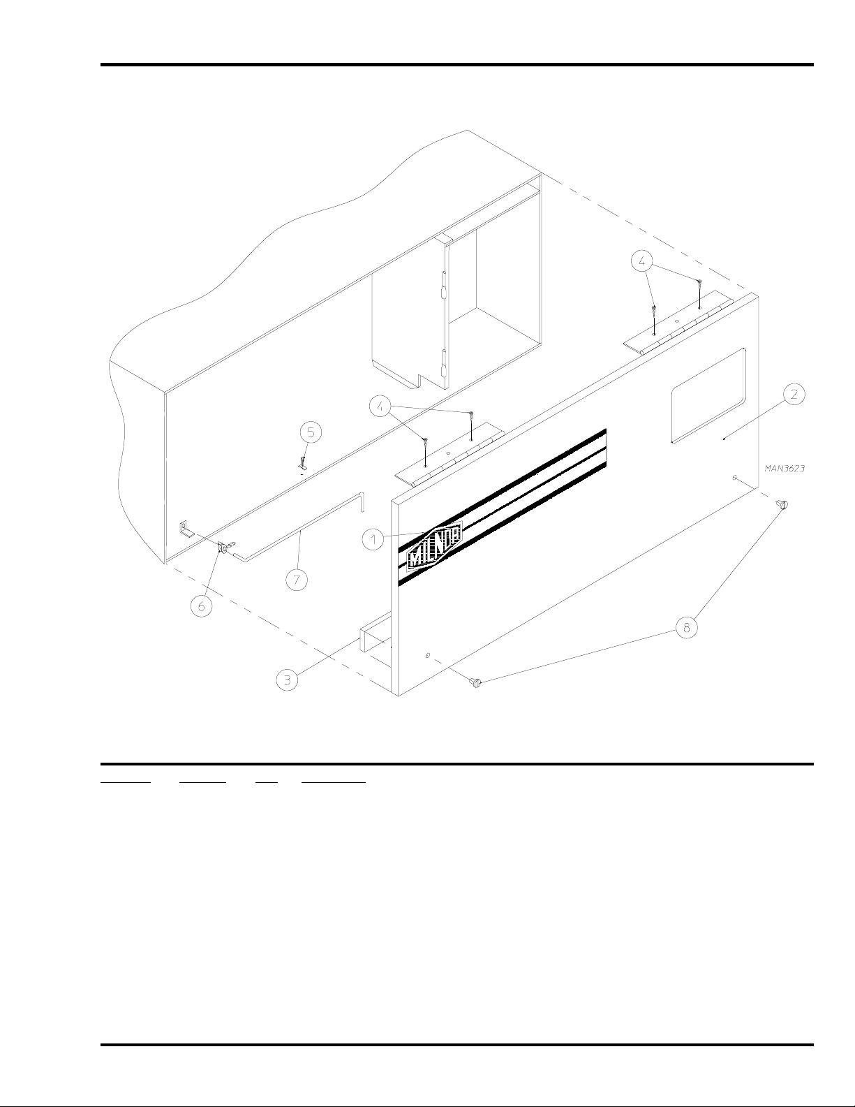
Front Panel / Main Door Assemblies with Mechanical Fasteners
Illus. No. Part No. Qty. Description
1 881871 1 White Front Panel Assembly
(includes illus. nos. 1, 12, and 13)
2 102214 1 30” Door Glass
170730 1 Door Glass / Gasket Adhesive (10.3 oz. cartridge)
3 151012 4 #10-32 Nylon Acorn Nut (white)
4 882411 1 Large Steel Door Gasket
170730 1 Door Glass / Gasket Adhesive (10.3 oz. cartridge)
5 881968 1 White Main Door Assembly with Mechanical Fasteners
(includes illus. nos. 2 through 11)
881966 1 White Main Door Ring
6 152014 6 1/4-20 Free Spin Wash Nut
7 881740 6 White 1/4-20 x 5/8” Carriage Bolt
8 881688 1 White Main Door Handle
9 881685 1 White Main Door Hinge
10 150120 1 Main Door Latch Screw
11 151012 1 #10-32 White Acorn Nut
12 170330 1 Friction Door Catch
13 154215 2 5/32” Pop Rivet
14 150445 4 1/4-20 x 3/4” Cap Screw
15 881440 1 White Top Hinge Block with Cap Screws
(includes illus. nos. 14 and 15)
16 881441 1 White Bottom Hinge Block with Cap Screws
(includes illus. nos. 14, 16, and 17)
17 153031 1 Nylon Washer
450564-3 www.amdry.com 13
Page 14
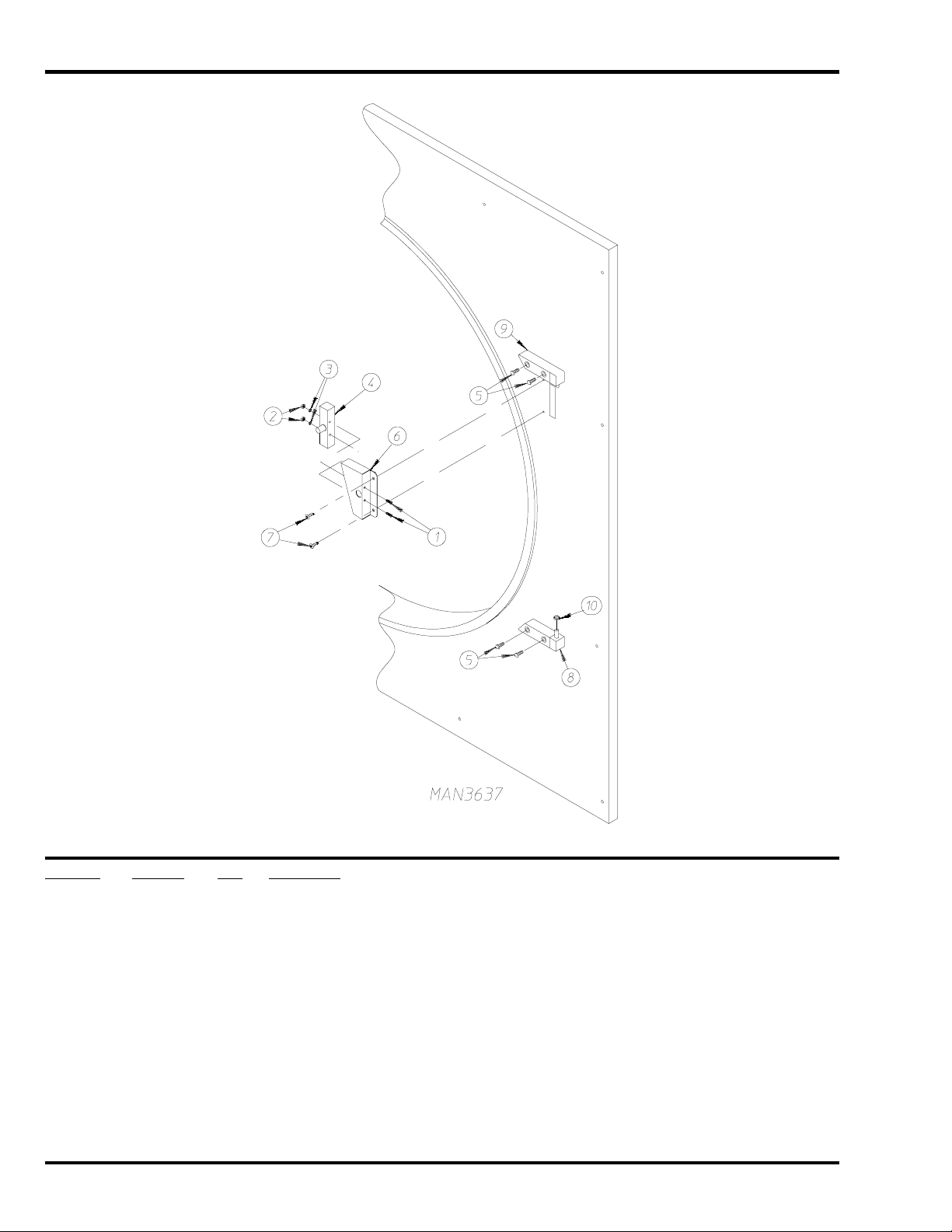
Main Door Switch Assembly
Illus. No. Part No. Qty. Description
1 150006 2 #6-32 x 7/8” Phillips Pan Head Machine Screw
2 152013 2 #6-32 Hex Nut
3 153010 2 #6 Star Washer
4 137005 1 Single-Pole Door Switch
5 150445 4 1/4-20 x 3/4” Cap Screw
6 881687 1 White Main Door Switch Housing ONLY
881702 1 White Main Door Switch with Housing Assembly
(includes illus. nos. 1 through 4 and 6)
7 150301 2 #8-18 x 7/16” Phillips Pan Head TEK Screw
8 881441 1 White Bottom Hinge Block with Cap Screw
(includes illus. nos. 5, 8 and 10)
9 881440 1 White Top Hinge Block with Cap Screw
(includes illus. nos. 5 and 9)
10 153031 1 Nylon Washer
14 American Dryer Corporation 450564 -3
Page 15
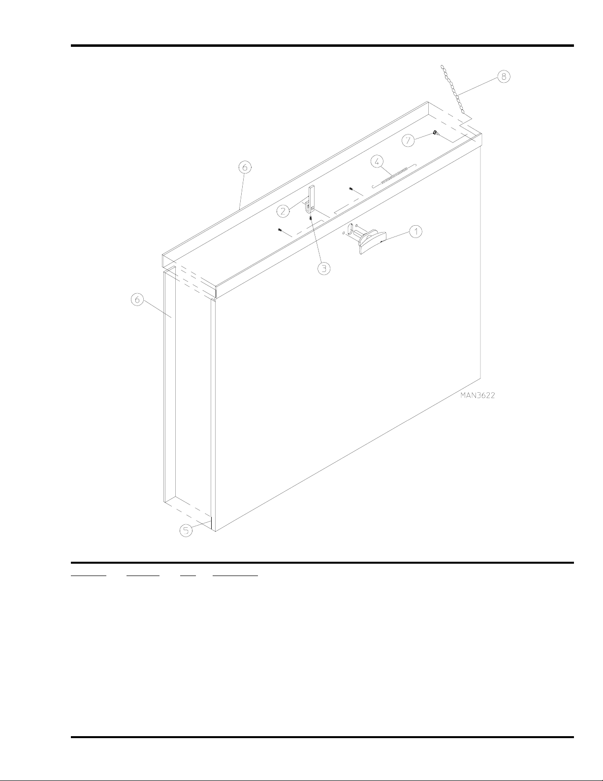
Drop Lint Door Assembly
Illus. No. Part No. Qty. Description
1 800150 1 Knob Latch Kit Assembly
(includes illus. nos. 1 through 3)
2 160009 1 Knob Latch Adjustable Cam ONLY
3 150425 1 #12-24 x 3/8” Round Head Machine Screw ONLY
(screw for knob latch adjustable cam)
4 157000 1 Drop Lint Door Spring
5* 881870 1 White Drop Lint Door Assembly
(includes illus. nos. 5 and 6)
6 117604 7 Noise Suppressor Tape (sold by the foot)
7 150419 2 #6 x 1/2” Tamperproof TEK Screw
8 108120 1 Chain for Drop Lint Door (10-1/2” length)
* Specify color when ordering.
450564-3 www.amdry.com 15
Page 16
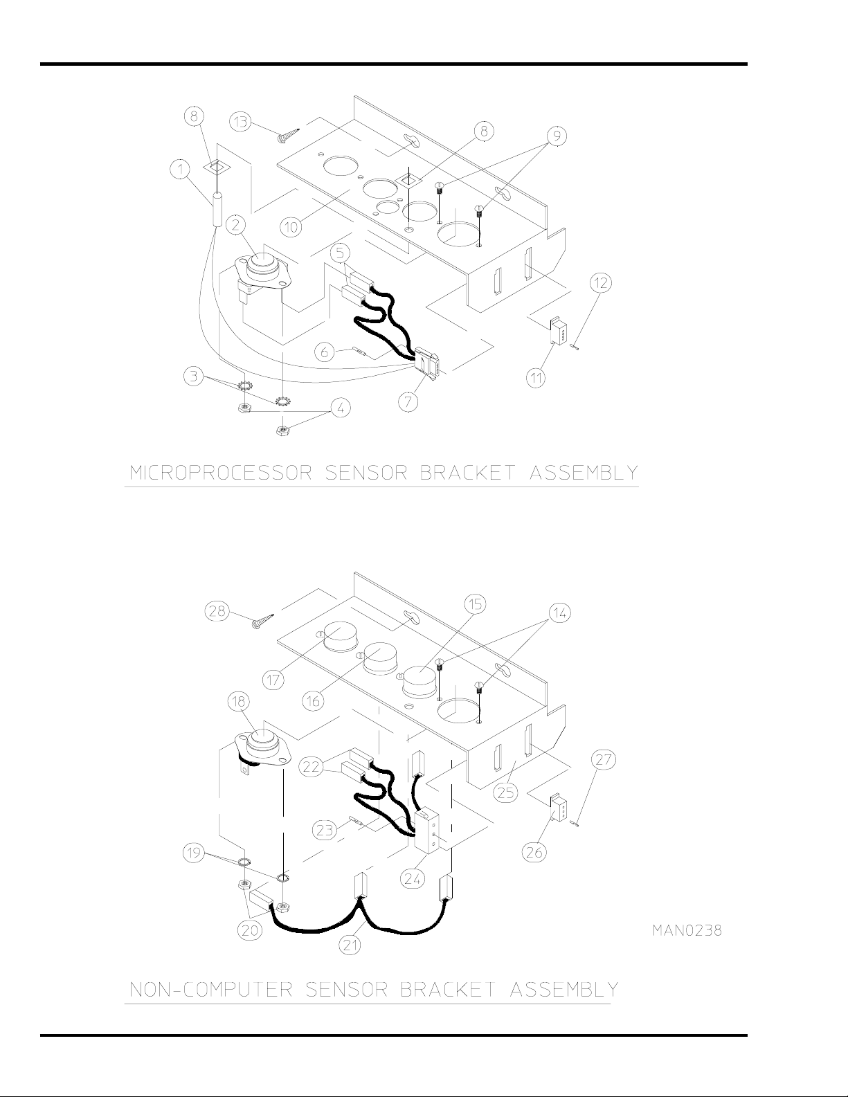
Sensor Bracket Assemblies
16 American Dryer Corporation 450564 -3
Page 17

Illus. No. Part No. Qty. Description
1 880251 1 1/4” Temperature Sensor Probe Assembly
(includes illus. nos. 1 and 5 through 8)
2 130103 1 225° Large Automatic Thermostat
3 153010 2 #6 Star Washer
4 152000 2 #6-32 Hex Nut
5 121028 2 Insulated Terminal ONLY
6 122701 4 Socket Terminal ONLY
7 122605 1 4-Pin Socket Connector ONLY
8 154007 2 1/4” Tinnerman Push-On Fastener
9 150005 2 #6-32 x 1/4” Round Head Machine Screw
10 801425 1 Microprocessor Sensor Bracket Assembly Complete
(includes illus. nos. 1 through 10)
305007 1 Universal Sensor Bracket ONLY
11 122604 1 4-Pin Connector ONLY
12 122700 4 Pin Terminal ONLY
13 150301 2 #8-18 x 7/16” Phillips Pan Head TEK Screw
14 150005 5 #6-32 x 1/4” Phillips Round Head Machine Screw
15 130111 1 130° Large Thermostat
16 130100 1 150° Large Thermostat
17 130103 1 225° Large Automatic Reset Thermostat
18 130101 1 180° Large Thermostat
19 153010 5 #6 Star Washer
20 152000 5 #6-32 Hex Nut
21 840065 1 Sensor Jumper (4) ONLY
22 121028 8 Insulated Terminal ONLY
23 122701 4 Socket Terminal ONLY
24 122605 1 4-Pin Socket Connector ONLY
840062 1 Sensor (4) Bracket Harness Assembly
(includes illus. nos. 22 through 24)
25 801418 1 Noncomputer Sensor (4) Bracket Assembly Complete
(includes illus. nos. 14 through 25)
305007 1 Universal Sensor Bracket ONLY
26 122604 1 4-Pin Connector ONLY
27 122700 4 Pin Terminal ONLY
122801 1 Pin / Socket Extraction Tool
28 150301 2 #8-18 x 7/16” Phillips Pan Head TEK Screw
Sensor Bracket Assemblies
450564-3 www.amdry.com 17
Page 18

Lint Trap Assembly
Illus. No. Part No. Qty. Description
1 800402 1 Non-Reversing Lint Trap Assembly Complete
(includes illus. nos. 1 and 3 through 5)
800404 1 Non-Reversing Lint Trap ONLY
800407 1 Reversing Lint Trap Assembly Complete
(includes illus. nos. 1 and 3 through 5)
800406 1 Reversing Lint Trap ONLY
2 154200 7 5/32” Pop Rivet
3 304101 1 Lint Screen Holder ONLY
4 150300 2 #10-16 x 1/2” Hex Washer TEK Screw
5 800501 1 Lint Screen ONLY
6 150419 2 #6 x 1/2” Tamperproof TEK Screw
7 108120 1 Chain for Drop Lint Door (10-1/2” length)
8 150425 2 #12-24 x 3/8” Phillips Round Head Machine Screw
9 122116 1 Lint Drawer Switch ONLY
10 323724 1 Lint Drawer Switch Bracket Assembly
18 American Dryer Corporation 450564 -3
Page 19

Tumbler / Support Assemblies
Illus. No. Part No. Qty. Description
1 881774 1 Tumbler ONLY with Felt Collar
881829 1 Non-Reversing Tumbler and Support Assembly Complete
(includes illus. nos. 1 through 10)
881777 1 Reversing Tumbler and Support Assembly Complete
(includes illus. nos. 1 through 10)
2 150309 40 #10-16 x 1/2” Hex Head TEK Crimptite Screw
3 301316 4 Tumbler Rib ONLY
4 115986 1 Felt Tumbler Pad
(for models mfd. as of January 22, 2002)
5 150407 1 5/16-18 x 3/4” Socket Button Head Screw
(for models mfd. prior to January 22, 2002)
6 881828 1 Non-Reversing Tumbler Support ONLY
881776 1 Reversing Tumbler Support ONLY
7 116000 1 Felt Collar ONLY
401010 1 #847 Adhesive for Felt Collar
8 153004 8 3/8” Flat Washer
9 100915 4 3/8-16 x 31-1/8” Tie Rod
10 152005 4 3/8” Hex Nut
11 153005 4 3/8” Lock Washer
450564-3 www.amdry.com 19
Page 20

Tumbler Bearing Assembly
20 American Dryer Corporation 450564 -3
Page 21

Tumbler Bearing Assembly
Illus. No. Part No. Qty. Description
1 880220 1 1-3/4” Flange Bearing
2 153025 4 9/16” Lock Washer
3 152050 4 9/16-12 Hex Nut
4 883387 1 Pillow Block Bearing Assembly Complete
(includes illus. nos. 4 through 18, 23, and 24)
882543 1 Pillow Block Bearing Platform ONLY
5 880779 1 1-3/8” Pillow Block Bearing
6 150601 2 3/8-16 x 2” Hex Bolt
7 153004 2 3/8” Flat Washer
8 153004 2 3/8” Flat Washer
9 153005 2 3/8” Lock Washer
10 152005 2 3/8-16 Hex Nut
11 154321 2 5/16-24 x 3/8” Setscrew
12 152004 2 5/16-18 Hex Nut
13 150621 2 5/16-18 x 1-1/2” Tap Bolt
14 153002 4 5/16” Lock Washer
15 153004 6 3/8” Flat Washer
16 150501 4 5/16-18 x 3/4” Tap Bolt
17 102120 1 Sintered 8 Magnet
18 883386 1 Rotational Sensor Assembly
19 100724 1 Shaft Key (for non-reversing models Only)
100735 1 Shaft Key (for reversing models Only)
20 884042 1 18” Pulley (for non-reversing models Only)
101118 1 18-3/4” Pulley (for reversing models Only)
21 101110 1 1” Taper Lock Bushing (for reversing models Only)
22 100108 1 5L-680 V-Belt (tumbler to idler) for Non-Reversing Models ONLY
100106 1 5L-690 V-Belt (tumbler to idler) for Reversing Models ONLY
23 150610 2 5/16-18 x 1-1/2 Allen Setscrew
24 152004 2 5/16-18 Hex Nut
450564-3 www.amdry.com 21
Page 22

Non-Reversing T.E.F.C. Motor Mount Assembly
22 American Dryer Corporation 450564 -3
Page 23

Non-Reversing T.E.F.C. Motor Mount Assembly
Illus. No. Part No. Qty. Description
1 100109 1 4L-650 V-Belt (motor to idler)
2 100701 1 3/16” x 3/16” x 1” Key
3 101130 1 5/8” x 2-1/2” Motor Pulley (for 60 Hz models Only)
101139 1 5/8” x 2-3/4” Motor Pulley (for 50 Hz models Only)
4 150501 4 5/16-18 x 3/4” Hex Head Machine Bolt
5 153002 4 5/16” Lock Washer
6 153001 4 5/16” Flat Washer
7 100069 1 3/4 hp 120/230v 1ø 60 Hz Totally Enclosed, Fan-Cooled Motor with Plug (56Z frame)
100068 1 3/4 hp 240v 1ø 50 Hz Totally Enclosed, Fan-Cooled Motor with Plug
8 122701 8 Socket Terminal ONLY
122801 1 Pin / Socket Extraction Tool
9 137030 1 8-Pin Housing Connector
10 152004 4 5/16-18 Hex Nut
11 153002 4 5/16” Lock Washer
12 153001 4 5/16” Flat Washer
13 117604 4 Noise Suppressor Tape (sold by the foot)
14 154000 4 5/16-18 Tinnerman Nut
15 850017 1 Non-Reversing Motor Mount ONLY (56Z frame)
803768 1 3/4 hp 120/230v 1ø 60 Hz
Totally Enclosed, Fan-Cooled Motor Mount Assembly Complete with Plug Motor
(includes illus. nos. 2 through 7 and 13 through 20)
803848 1 3/4 hp 230v 1ø 50 Hz
Totally Enclosed, Fan-Cooled Motor Mount Assembly Complete with Plug Motor
(includes illus. nos. 2 through 7 and 13 through 20)
803854* 1 1/2 hp 208/230/380/460v 3ø 60 Hz
Non-Reversing Totally Enclosed, Fan-Cooled Motor Mount Assembly Complete
(includes illus. nos. 2 through 6 and 13 through 22)
803856* 1 1/2 hp 208/230/380/460v 3ø 50 Hz
Non-Reversing Totally Enclosed, Fan-Cooled Motor Mount Assembly Complete
(includes illus. nos. 2 through 6 and 13 through 22)
16 153050 2 1/2” S.A.E. Flat Washer
17 100604 1 12-1/2” Impellor with 1/2” Bore
18 100702 1 1/8” x 1/8” x 1-1/2” Key
19 153050 2 1/2” S.A.E. Flat Washer
20 152006 2 1/2-20 Left Hand Jam Nut
21 120200 1 3/8” x 90° Connector
22* 100007 1 1/2 hp 208/230/240/460v 3ø 50/60 Hz Totally Enclosed, Fan-Cooled Motor (56Z frame)
* Specify volt age when ordering.
450564-3 www.amdry.com 23
Page 24

Reversing T.E.F.C. Motor Mount Assembly
24 American Dryer Corporation 450564 -3
Page 25

Reversing T.E.F.C. Motor Mount Assembly
Illus. No. Part No. Qty. Description
1 100109 1 4L-650 V-Belt (motor to idler)
2 100701 1 3/16” x 3/16” x 1” Key
3 101130 1 5/8” x 2-1/2” Motor Pulley (for 60 Hz models Only)
101133 1 5/8” x 2-3/4” Motor Pulley (for 50 Hz models Only)
4 120200 1 3/8” x 90° Connector
5* 181003 1 1/2 hp 208/230/380/460v 3ø 50/60 Hz
Totally Enclosed, Fan-Cooled Motor (56Z frame)
6 150501 4 5/16-18 x 3/4” Hex Head Machine Bolt
7 153002 4 5/16” Lock Washer
8 153001 4 5/16” Flat Washer
9* 100007 1 1/2 hp 208/230/240/460v 3ø 50/60 Hz
Totally Enclosed, Fan-Cooled Motor (56Z frame)
10 120200 1 3/8” x 90° Connector
11 150501 4 5/16-18 x 3/4” Hex Head Machine Bolt
12 153002 4 5/16” Lock Washer
13 153001 4 5/16” Flat Washer
14 154000 8 5/16” Tinnerman Nut
15 152004 4 5/16” Hex Nut
16 153002 4 5/16” Lock Washer
17 153001 4 5/16” Flat Washer
18 800912 1 Reversing Motor Mount ONLY (56Z frame)
803974* 1 Reversing Totally Enclosed, Fan-Cooled Motor Mount Assembly Complete
(for 60 Hz models Only)
(includes illus. nos. 2 through 14 and 18 through 24)
803912* 1 Reversing Totally Enclosed, Fan-Cooled Motor Mount Assembly Complete
(for 50 Hz models Only)
(includes illus. nos. 2 through 14 and 18 through 24)
19 117604 4 Noise Suppressor Tape (sold by the foot)
20 153050 2 1/2” S.A.E. Flat Washer
21 100702 1 1/8” x 1/8” x 1-1/2” Key
22 100604 1 12-1/2” Impellor with 1/2” Bore
23 153050 2 1/2” S.A.E. Flat Washer
24 152006 2 1/2-20 Left Hand Jam Nut
* Specify volt age when ordering.
450564-3 www.amdry.com 25
Page 26

Direct Spark Ignition Burner Assembly
26 American Dryer Corporation 450564 -3
Page 27

Direct Spark Ignition Burner Assembly
Illus. No. Part No. Qty. Description
1 141105 3 Large Tube Burner
2 151001 3 #8-32 Pal Nut
3 150108 3 #8-32 x 1/2” Pan Head Machine Screw
4* 140820 3 #29 Natural Gas Burner Orifice
140804 3 #48 Liquid Propane Burner Orifice
5 141232 1 1/2” Direct Spark Ignition Manifold (3-port)
6 150309 3 #10-16 x 1/2” Hex Head TEK Crimptite Screw
7 318716 1 Gas Valve Bracket
8 128927 1 1/2” 24 VAC Redundant (natural gas) Gas Valve
880960 1 1/2” 24 VAC Redundant (liquid propane gas) Gas Valve
9 880134 1 Ignitor Probe Assembly
882537 1 Flame-Probe Wire
10 150300 2 #10-16 x 1/2” Hex Washer TEK Screw
11 817027 1 Direct Spark Ignition Module Mounting Bracket Assembly
12 883849 1 Johnson Controls Direct Spark Ignition Module with 3 Tries
13 152013 2 #6-32 Hex Nut
14 142707 1 1/2” x 1-1/2” Black Nipple
15 142506 1 1/2” Street Elbow
16 142600 1 1/2” Black Union
17 142809 1 1/2” x 29” Pipe / Nipple
18 809707 1 Direct Spark Ignition Burner Assembly Complete (natural gas)
(includes illus. nos. 1 through 3 and 5 through 18)
809708 1 Direct Spark Ignition Burner Assembly Complete (liquid propane gas)
(includes illus. nos. 1 through 3 and 5 through 18)
850852 1 Direct Spark Ignition Burner Box ONLY
881598* 1 ML-55 Liquid Propane Conversion Kit (includes orifices)
* Consult factory for elevations over 2,000 feet.
450564-3 www.amdry.com 27
Page 28

Hot Surface Ignition Burner Assembly
28 American Dryer Corporation 450564 -3
Page 29

Hot Surface Ignition Burner Assembly
Illus. No. Part No. Qty. Description
1 318403 1 Hot Surface Ignition Burner Shield
2 881597 1 Hot Surface Ignitor – 24 VAC (2-1/2” length)
3 128921 1 Hot Surface Ignition Flame Sensor
4 150309 2 #10-16 x 1/2” Hex Head TEK Crimptite Screw
5 141105 3 Large Burner Tube
6 150103 1 #8-32 x 1/2” Phillips Round Head Machine Screw
7 153000 1 #8 Steel Burr
8 151001 1 #8-32 Pal Nut
9* 140820 3 #29 Natural Gas Orifice
140804 3 #48 Liquid Propane Gas Orifice
10 141232 1 3-Port Manifold
11 318700 1 Pipe Bracket
12 150300 2 #10-16 x 1/2” Hex Washer TEK Screw
13 128927 1 1/2” 24 VAC Redundant (natural gas) Gas Valve
880960 1 1/2” 24 VAC (liquid propane gas) Gas Valve Assembly
14 318712 2 GV Pipe Bracket
15 150309 2 #10-32 x 1/2” Hex Head TEK Crimptite Screw
16 142707 1 1/2” x 1-1/2” Black Iron Nipple
17 142506 1 1/2” Street Elbow
18 142600 1 1/2” Union
19 150301 1 #8-18 x 7/16” Phillips Pan Head TEK Screw
20 810029 1 Hot Surface Ignition Module Bracket Assembly
21 881797 1 Hot Surface Ignition Module II
22 151001 2 #8-32 Pal Nut
—* 881598 1 Hot Surface Ignition Liquid Propane Conversion Kit
23 142809 1 1/2” x 29-1/8” Pipe
24 809712** 1 Natural Gas Burner Assembly
(includes illus. nos. 1 through 8 and 10 through 24)
809713 1 Liquid Propane Assembly
(includes illus. nos. 1 through 8 and 10 through 24)
850843 1 Hot Surface Ignition Burner Box ONLY
* Consult factory for elevations over 2,000 feet.
** Burner orifices are not included and must be ordered separately.
450564-3 www.amdry.com 29
Page 30

Idler Bearing Assembly
Illus. No. Part No. Qty. Description
1 100108 1 5L-680 V-Belt (non-reversing)
100106 1 5L-690 V-Belt (reversing)
2 101140 1 14” x 3” Compound Pulley
3 100109 1 4L-650 V-Belt (idler to motor) Non-Reversing / Reversing Models
4 154301 2 5/16-18 x 1” Allen Setscrew
5 100705 1 3/16” x 3/16” x 1-3/8” Key
6 882576 1 Idler Bearing Assembly Complete
(includes illus. nos. 5 through 12)
7 150617 2 3/8-16 x 1” Hex Head Machine Bolt
8 153005 2 3/8” Lock Washer
9 153004 2 3/8” Flat Washer
10 801009 1 Idler Square Washer
11 152004 1 5/16-18 Hex Nut
12 150509 1 5/16-18 x 3” Hex Head Machine Bolt
30 American Dryer Corporation 450564 -3
Page 31

Sail Switch / Hi-Limit Assemblies
Illus. No. Part No. Qty. Description
1 154004 1 Twin Speed Nut
2 150309 2 #10-16 x 1/2” Hex Head TEK Crimptite Screw
3 802799 1 Sail Switch Box Cover and Bracket ONLY
4 150303 2 #4 x 3/4” Pan Head “A” Machine Screw
5 122200 1 Sail Switch ONLY
(for microprocessor controller [computer] models Only)
122404 1 Sail Switch ONLY
(for non-microprocessor models)
6 105500 1 Sail Switch Actuator Rod
7 319202 1 Sail Switch Damper (flat)
8 154002 1 1/8” Push-On Fastener
9 802800 1 Sail Switch Box with Cover and Bracket ONLY
802801 1 Sail Switch Assembly Complete for Microprocessor Models ONLY
(includes illus. nos. 1 through 8)
10 142809 1 1/2” x 29-1/8” Pipe
11 150309 2 #10-16 x 1/2” Hex Head TEK Crimptite Screw
12 319704 1 Hi-Limit Mounting Bracket ONLY
13 151000 2 #6-32 Pal Nut
14 150001 2 #6-32 x 1/2” Round Head Machine Screw
15 130201 1 330° Hi-Limit ONLY
16 143000 1 1/2” x 3/4” Reducing Coupling
450564-3 www.amdry.com 31
Page 32

Air-Operated S team Damper Assembly
32 American Dryer Corporation 450564 -3
Page 33

Air-Operated S team Damper Assembly
Illus. No. Part No. Qty. Description
1 165011 1 Steam Coil Assembly
2 153002 6 5/16” Lock Washer
3 152004 6 5/16-18 Hex Nut
4 152002 4 1/4-20 Hex Nut
5 153007 4 1/4” Lock Washer
6 820321 2 Steam Damper Hinge Assembly
7 803416 1 Steam Damper Assembly
(includes illus. nos. 7, 10, and 11)
8 153007 4 1/4” Lock Washer
9 152002 4 1/4-20 Hex Nut
10 115995 66 Steam Damper Gasket (sold by the inch)
11 102350 1 Steam Damper Foam (68-1/2” length)
12 151006 1 5/16-24 Stainless Steel Acorn Nut
13 152051 1 5/16-24 Right Hand Jam Nut
14 100497 1 1-1/4” Bore x 3” Stroke Piston
15 100492 2 Piston Support Bracket
16 152002 2 1/4-20 Hex Nut
17 153007 2 1/4” Lock Washer
18 100472 1 1/4” Poly x 1/8” M.P.T. Connector
19 143110 1 1/4” Poly-Flo Tubing (sold by the foot)
20 100472 1 1/4” Poly x 1/8” M.P.T. Connector
21 100496 1 1/8” Needle Valve
22 143238 1 1/8” Close Nipple
23 100498 1 3-Way Micro Valve – 24 VAC
24 150002 2 #6-32 x 1” Slotted Machine Screw
25 153010 2 #6 Star Washer
26 152000 2 #6-32 Hex Nut
27 330987 1 Micro Valve Support Bracket
28 152002 2 1/4-20 Hex Nut
29 153007 2 1/4” Lock Washer
30 100520 1 1/8” N.P.T. Silencer (muffler)
450564-3 www.amdry.com 33
Page 34

Electric Oven Assembly
34 American Dryer Corporation 450564 -3
Page 35

Illus. No. Part No. Qty. Description
1 803007* 1 Large Electric Oven Box ONLY
––––––* 1 Electric Oven Assembly Complete
2 ––––––* — Electric Element
3 150300 2 #10-16 x 1/2” Hex Washer TEK Screw
4 802800 1 Sail Switch Box with Bracket and Cover ONLY
802801 1 Sail Switch Box Assembly Complete
(includes illus. nos. 4 through 12)
5 154004 1 Twin Speed Nut
6 150300 2 #10-16 x 1/2” Hex Washer TEK Screw
7 802799 1 Sail Switch Box Cover and Bracket ONLY
8 122200 1 Sail Switch ONLY
9 150303 2 #4 x 3/4” Phillips Pan Head “A” Machine Screw
10 105500 1 Sail Switch Actuator Rod
11 319202 1 Sail Switch Damper (flat)
12 154002 1 1/8” Push-On Fastener
13 150300 2 #10-16 x 1/2” Hex Washer TEK Screw
14 803100 1 Electric Oven Front Cover ONLY
15 320611 1 Large Relay Box Cover ONLY
16 150301 2 #8-18 x 7/16” Phillips Pan Head TEK Screw
17 130201 1 290° Hi-Limit Thermostat
18 150300 2 #10-16 x 1/2” Hex Washer TEK Screw
19 154001 2 #10-24 Speed Nut
20 121010 1 L-70 Ground Lug
21 152014 3 1/4-20 Free Spin Wash Nut
22 ––––––* 1 Oven Relay
23 150207 2 #10-24 x 1/2” Phillips Pan Head Machine Screw
24 120081 — Internal Ceramic Insulator (2 per element)
25 120080 — External Ceramic Insulator (2 per element)
26 152008 — #10-32 Hex Nut (4 per element)
27 121011 — Bus Bar (sold by the foot)
28 ––––––* — Oven Wiring
29 153009 — #10 Star Washer (2 per element)
30 321301 1 Large Electric Oven Right Side Cover ONLY
883310** 1 Steam to Electric Transition Plate … Not Illustrated
Electric Oven Assembly
* Refer to Electric Oven Component Application Chart on page 49.
** Needed when converting dryer from steam heat to electric heat.
450564-3 www.amdry.com 35
Page 36

Single-Phase (1ø) MP Rear Electric Relay Panel Assembly
Illus. No. Part No. Qty. Description
1 151000 2 #6-32 Pal Nut
2 150300 2 #10-16 x 1/2” Hex Washer TEK Screw
3 150008 2 #6-32 x 1-1/4” Phillips Pan Head Machine Screw
4 120716 1 2-Position Terminal Block
5 322812 1 Rear Electric Mounting Plate ONLY
822796 1 Rear Electric Panel Assembly Complete – 115 Volt 1ø (for gas models Only)
(includes illus. nos. 1 through 14)
830153 1 Rear Electric Panel Assembly Complete – 115 Volt 1ø (for steam models Only)
(includes illus. nos. 1 through 14)
822798 1 Rear Electric Panel Assembly Complete – 208-240 Volt 1ø (for gas models Only)
(includes illus. nos. 1 through 14)
830273 1 Rear Electric Panel Assembly Complete – 208-240 Volt 1ø (for steam models Only)
(includes illus. nos. 1 through 14)
830131 1 Rear Electric Panel Assembly Complete – 208-240 Volt (for electric models Only)
(includes illus. nos. 1 through 14 and 16)
6 830151 1 Transformer Assembly – 115 Volt
822799 1 Transformer Assembly – 208-240 Volt (for gas and steam models Only)
822792 1 Transformer Assembly – 208-240 Volt (for electric models Only)
7 136008 * Fuse Holder ONLY
8 136057 * 1/2-Amp (Slo-Blo) Fuse ONLY
9 150301 4 #8-18 x 7/16” Phillips Pan Head TEK Screw
10 150297 1 #10 x 1/2” Green Hex Washer TEK Screw
11 152004 1 5/16-18 Hex Nut
12 121010 1 L-70 Ground Lug
13 153002 1 5/16” Lock Washer
14 132495 1 3-Pole Contactor
15 121300 3 Open / Closed Bushing
16 131932 1 24V SPST Relay (for electric heated models Only)
* Quantity is 1 for 1 15v and 2 for 208-240v.
36 American Dryer Corporation 450564 -3
Page 37

208-240V 3-Phase (3ø) MP Rear Electric Relay Panel Assembly
Illus. No. Part No. Qty. Description
1 151000 2 #6-32 Pal Nut
2 150300 2 #10-16 x 1/2” Hex Washer TEK Screw
3 150008 2 #6-32 x 1-1/4” Phillips Pan Head Machine Screw
4 120701 1 4-Position Terminal Block
5 322812 1 Rear Electric Mounting Plate ONLY
830154 1 Rear Electric Panel Assembly Complete – 208-240 Volt (for gas models Only)
(includes illus. nos. 1 through 14)
830322 1 Rear Electric Panel Assembly Complete – 208-240 Volt (for steam models Only)
(includes illus. nos. 1 through 14)
830157 1 Rear Electric Panel Assembly Complete – 208-240 Volt (for electric models Only)
(includes illus. nos. 1 through 14 and 16)
6 822799 1 Transformer Assembly (for gas and steam models Only)
822792 1 Transformer Assembly (for electric models Only)
7 136008 2 Fuse Holder ONLY
8 136057 2 1/2-Amp (Slo-Blo) Fuse ONLY
9 150301 4 #8-18 x 7/16” Phillips Pan Head TEK Screw
10 150297 1 #10 x 1/2” Green Hex Washer TEK Screw
11 152004 1 5/16-18 Hex Nut
12 121010 1 L-70 Ground Lug
13 153002 1 5/16” Lock Washer
14 132495 1 3-Pole Contactor
15 121300 3 Open / Closed Bushing
16 131932 1 24V SPST Relay (for electric heated models Only)
450564-3 www.amdry.com 37
Page 38

480V MP Rear Electric Relay Panel Assembly
Illus. No. Part No. Qty. Description
1 150300 2 #10-16 x 1/2” Hex Washer TEK Screw
2 150008 2 #6-32 x 1-1/4” Phillips Pan Head Machine Screw
3 120701 1 4-Position Terminal Block
4 135501 1 2-Pole 1-Amp Circuit Breaker
5 824221 1 Transformer Assembly – 460-480 Volt
6 120768 2 35 x 15mm Din Rail
7 120765 2 End Stop
8 150301 4 #8-18 x 7/16” Phillips Pan Head TEK Screw
9 150297 2 #10 x 1/2” Green Hex Washer TEK Screw
10 152004 1 5/16-18 Hex Nut
11 121010 2 L-70 Ground Lug
12 153002 1 5/16” Lock Washer
13 132495 1 3-Pole Contactor
14 322812 1 Rear Electric Mounting Plate ONLY
830263 1 Rear Electric Panel Assembly Complete – 460-480 Volt (for gas models Only)
(includes illus. nos. 1 through 14)
830137 1 Rear Electric Panel Assembly Complete – 460-480 Volt (for steam models Only)
(includes illus. nos. 1 through 14)
830199 1 Rear Electric Panel Assembly Complete – 460-480 Volt (for electric models Only)
(includes illus. nos. 1 through 14 and 16)
15 151000 2 #6-32 Pal Nut
16 131932 1 24V SPST Relay (for electric heated models Only)
17 112075 1 Ground Label
38 American Dryer Corporation 450564 -3
Page 39

208-240V MP Reversing Rear Electric Relay Panel Assembly
Illus. No. Part No. Qty. Description
1 150300 2 #10-16 x 1/2” Hex Washer TEK Screw
2 150008 2 #6-32 x 1-1/4” Phillips Pan Head Machine Screw
3 120701 1 4-Position Terminal Block
4 132497 1 3-Pole Reversing Contactor
5 822799 1 Transformer Assembly – 208-240 Volt (for gas and steam models Only)
822792 1 Transformer Assembly – 208-240 Volt (for electric models Only)
6 136008 2 Fuse Holder ONLY
7 136057 2 1/2-Amp (Slo-Blo) Fuse ONLY
8 150301 4 #8-18 x 7/16” Phillips Pan Head TEK Screw
9 150297 1 #10 x 1/2” Green Hex Washer TEK Screw
10 152004 1 5/16-18 Hex Nut
11 121010 1 L-70 Ground Lug
12 153002 1 5/16” Lock Washer
13 132495 1 3-Pole Contactor
14 322812 1 Rear Electric Mounting Plate ONLY
822771 1 Rear Electric Panel Assembly Complete – 208-240 Volt 3ø (for gas models Only)
(includes illus. nos. 1 through 16)
830167 1 Rear Electric Panel Assembly Complete – 208-240 Volt 3ø (for steam models Only)
(includes illus. nos. 1 through 16)
822789 1 Rear Electric Panel Assembly Complete – 208-240 Volt 3ø (for electric models Only)
(includes illus. nos. 1 through 17)
15 151000 2 #6-32 Pal Nut
16 120765 1 Standard End Bracket
17 131932 1 24V SPST Relay (for electric heated models Only)
450564-3 www.amdry.com 39
Page 40

460-480V MP Reversing Rear Electric Relay Panel Assembly
Illus. No. Part No. Qty. Description
1 150300 2 #10-16 x 1/2” Hex Washer TEK Screw
2 150008 2 #6-32 x 1-1/4” Phillips Pan Head Machine Screw
3 120701 1 4-Position Terminal Block
4 135501 1 2-Pole 1-Amp Circuit Breaker
5 824221 1 Transformer Assembly – 460-480 Volt
6 120768 2 35 x 15mm Din Rail
7 120765 2 Standard End Bracket
8 150301 4 #8-18 x 7/16” Phillips Pan Head TEK Screw
9 150297 1 #10 x 1/2” Green Hex Washer TEK Screw
10 152004 1 5/16-18 Hex Nut
11 121010 1 L-70 Ground Lug
12 153002 1 5/16” Lock Washer
13 132495 1 3-Pole Contactor
14 322812 1 Rear Electric Mounting Plate ONLY
830147 1 Rear Electric Panel Assembly Complete – 460-480 Volt (for gas models Only)
(includes illus. nos. 1 through 16)
830103 1 Rear Electric Panel Assembly Complete – 460-480 Volt (for steam models Only)
(includes illus. nos. 1 through 16)
824371 1 Rear Electric Panel Assembly Complete – 460-480 Volt (for electric models Only)
(includes illus. nos. 1 through 17)
15 151000 2 #6-32 Pal Nut
16 132497 1 3-Pole Reversing Contactor
17 112075 1 Ground Label
18 131932 1 24V SPST Relay (for electric heated models Only)
40 American Dryer Corporation 450564 -3
Page 41

Single-Phase (1ø) Dual Timer Rear Electric Relay Panel Assembly
Illus. No. Part No. Qty. Description
1 150300 2 #10-16 x 1/2” Hex Washer TEK Screw
2 –––––– 1 24 VAC Transformer
(refer to Step Down Transformer Usage Listing on
3 132449 1 2-Pole Contact Block (for 208-240 volt models Only)
4 132445 1 3-Pole Contactor (for 120 volt models Only)
132447 1 3-Pole Contactor (for 208-240 volt models Only)
5 132383 1 2-Pole Contact Block (for 120 volt models Only)
6 150301 * #8-18 x 7/16” Phillips Pan Head TEK Screw
7 136008 * Fuse Holder ONLY
8 136057 * 1/2-Amp (Slo-Blo) Fuse
9 153002 1 5/16” Lock Washer
10 152004 1 5/16-18 Hex Nut
11 150297 1 #10 x 1/2” Hex Washer TEK Screw – Green
12 121010 1 L-70 Ground Lug
13 150300 2 #10-16 x 1/2” Hex Washer TEK Screw
14 353258 1 Rear Panel Connector Bracket
15 306304 1 Rear Electric Mounting Panel ONLY
830245 1 Rear Electric Panel Assembly Complete – 115 Volt
(includes illus. nos. 1, 2, and 4 through 18)
826463 1 Rear Electric Panel Assembly Complete – 208-240 Volt
(includes illus. nos. 1 through 4 and 6 through 18)
16 150008 2 #6-32 x 1-1/4” Phillips Round Head Machine Screw
17 120716 1 2-Position Terminal Block
18 151000 2 #6-32 Pal Nut
19 121300 3 Open / Closed Bushing
page 48)
* Quantity is 1 for 1 15v and 2 for 208-240v.
450564-3 www.amdry.com 41
Page 42

3-Phase (3ø) 208-240V Dual Timer Rear Electric Relay Panel Assembly
For Gas Models Only
Illus. No. Part No. Qty. Description
1 150300 2 #10-16 x 1/2” Hex Washer TEK Screw
2 –––––– 1 24 VAC Transformer
(refer to Step Down Transformer Usage Listing on
3 132449 1 2-Pole Contact Block
4 132447 1 3-Pole Contactor
5 121300 3 Open / Closed Bushing
6 150301 2 #8-18 x 7/16” Phillips Pan Head TEK Screw
7 136008 2 Fuse Holder ONLY
8 136057 2 1/2-Amp (Slo-Blo) Fuse
9 153002 1 5/16” Lock Washer
10 152004 1 5/16-18 Hex Nut
11 150297 1 #10 x 1/2” Hex Washer TEK Screw – Green
12 121010 1 L-70 Ground Lug
13 150300 2 #10-16 x 1/2” Hex Washer TEK Screw
14 353258 1 Rear Panel Connector Bracket
15 306304 1 Rear Electric Mounting Panel ONLY
–––––– * Rear Electric Panel Assembly Complete
16 150008 2 #6-32 x 1-1/4” Phillips Round Head Machine Screw
17 120701 1 4-Position Terminal Block
18 151000 2 #6-32 Pal Nut
* Not available at time of printing.
42 American Dryer Corporation 450564 -3
page 48)
Page 43

460-480V Dual Timer Rear Electric Relay Panel Assembly
For Gas Models Only
Illus. No. Part No. Qty. Description
1 150300 2 #10-16 x 1/2” Hex Washer TEK Screw
2 150008 2 #6-32 x 1-1/4” Phillips Round Head Machine Screw
3 120701 1 4-Position Terminal Block
4 –––––– 1 24 VAC Transformer
(refer to Step Down Transformer Usage Listing on
5 135501 1 1-Amp Double-Pole Circuit Breaker
6 120768 2 Din Rail (sold by the inch)
7 150297 1 #10 x 1/2” Hex Washer TEK Screw – Green
8 152004 1 5/16-18 Hex Nut
9 121010 1 L-70 Ground Lug
10 153002 1 5/16” Lock Washer
11 132447 1 3-Pole Contactor
12 322812 1 Rear Electric Mounting Panel ONLY
824231 1 Rear Electric Panel Assembly Complete
(includes illus. nos. 1 through 16)
13 151000 2 #6-32 Pal Nut
14 120765 2 Din Rail End Stop
15 132449 1 2-Pole Contact Block
16 353258 1 Rear Panel Connector Bracket
450564-3 www.amdry.com 43
page 48)
Page 44

208-240V Dual Timer Reversing Rear Electric Relay Panel Assembly
For Gas Models Only
Illus. No. Part No. Qty. Description
1 150009 2 #6-32 x 1-1/2” Phillips Round Head Machine Screw
2 120701 1 4-Position Terminal Block
3 150300 2 #10-16 x 1/2” Hex Washer TEK Screw
4 353258 1 Rear Panel Connector Bracket
5 132448 1 Reversing Contactor with 24 VAC Coil
6 132447 1 Blower Motor Contactor
7 152004 1 5/16-18 Hex Nut
8 153002 1 5/16” Lock Washer
9 322812 1 Rear Electric Mounting Panel ONLY
830236 1 Rear Electric Panel Assembly Complete
(includes illus. nos. 1 through 17)
10 151000 2 #6-32 Pal Nut
11 132449 1 2-Pole Contact Block
12 –––––– 1 24 VAC Transformer
(refer to Step Down Transformer Usage Listing on
13 136008 2 Fuse Holder ONLY
14 136057 2 1/2-Amp (Slo-Blo) Fuse
15 150301 2 #8-18 x 7/16” Phillips Pan Head TEK Screw
16 121010 1 L-70 Ground Lug
17 150297 1 #10 x 1/2” Hex Washer TEK Screw – Green
44 American Dryer Corporation 450564 -3
page 48)
Page 45

F.S.S. Temperature Probe Assembly
Illus. No. Part No. Qty. Description
1 822752 1 Fire Suppression System Temperature Probe Assembly
(includes illus. nos. 1 through 5)
2 154007 2 Push-On Fastener
3 390390 1 Sensor Bracket ONLY
4 150301 2 #8-18 x 7/16” Phillips Pan Head TEK Screw
5 122643 2 Pin
122647 1 Connector ONLY … Not Illustrated
450564-3 www.amdry.com 45
Page 46

F.S.S. Solenoid Assembly
Illus. No. Part No. Qty. Description
1 165114 1 Fire Suppression System Solenoid Valve 24V 50/60 Hz
2 143220 1 3/8” F.P.T. Brass Tee
3 143251 1 3/8” M.P.T. Brass Plug
4 143208 2 3/8” Comp x 3/8” M.P.T. Brass Connector
5 143099 6 ’ 3/8” OD x 0.035 Wall Copper Tubing (sold by the foot)
6 311588 1 Sprinkler Head Mounting Plate
7 143303 1 3/8” N.P.T. Brass Locknut
8 143155 1 3/8” Brass Elbow 90°
9 150430 2 #10 x 1/2” Self-Drilling Screw
10 150301 2 #8-18 x 7/16” Phillips Pan Head TEK Screw
11 143581 1 3 GPM 3/8” F.P.T. Spray Nozzle
12 142888 1 1/2” to 3/8” Bushing for Fire Suppression System Valve
13 824828 1 Arc Suppressor
46 American Dryer Corporation 450564 -3
Page 47

Outer Top / Back Guard Assemblies
Illus. No. Part No. Qty. Description
1 322809 1 Back Electrical Box Cover
2 150301 4 #8-18 x 7/16” Phillips Pan Head TEK Screw
3 314414 1 Top Back Guard (no top back guard on steam models)
4 150301 7 #8-18 x 7/16” Phillips Pan Head TEK Screw
5 150301 10 #8-18 x 7/16” Phillips Pan Head TEK Screw
6 312534 1 Outer Top (no outer top on steam models)
7 314518 1 Lower Back Guard
8 150301 13 #8-18 x 7/16” Phillips Pan Head TEK Screw
9 103500 4 Leveling Leg
450564-3 www.amdry.com 47
Page 48

Step Down Transformer Usage Listing
STEP DOWN TRANSFORMER USAGE LISTING
WIRE
ADC PART NO.
VOLTAGE
SERVICE
120 2 132070 132070 –––––
208/240 2 132082 132082 132063
208/240 3/4 132082 132082 132063
460/480 3/4 132067 132067 132067
NOTE: Each transformer requires 1 transformer termination kit (ADC Part No. 881763).
GAS STEAM ELECTRIC
48 American Dryer Corporation 450564 -3
Page 49

450564-3 www.amdry.com 49
Oven
kW Voltage Phase Wire
30 480 3Ø 3 826222 6 5 120013 1 #8 882572 1 121010 1 DPA43 131357
30 240 3Ø 3 833124 6 5 120013 1 #4 882566 1 121010 1 DPA73 131376
* Consult factory for oven assemblies not listed.
Assembly *
Part No.
Element
Qty. kW P art No. Qty. Size Part No. Qty. Part No. Cat. No. Part No.
Oven Wire
with Crimp Terminal
Ter minal L ug
Bus Bar
Part No.
121011
Oven Rela y
Electric Oven Component Application Chart
Page 50

Additional Parts Available
Part No. Description
112280 “Clean Lint Screen” Label
114001 “CAUTION – Exhaust Lint Screen” Label
114006 “WARNING – Fire Hazards” Label
120100 3/8” Straight (BX) Connector
120300 3/8” x 45° (BX) Connector
120400 3/8” Red Jacket (BX) Insulator
120500 3/8” Jiffy Clip (BX retainer clip)
120600 3/8” Greenfield (BX)
120800 1/4” In-Line Connector
120802 Red Butt Connector
120902 #74B Wire Nut
120903 Crimp-On Wire Nut
121014 1/4” Insulated (female) Terminal
121499 5-1/2” Harness Tie
121500 8” Harness Tie
121503 Harness Tie Mounting Clip
122804 Manometer (hydro gauge) for Measuring Gas Pressure
404502 White Brush-In-Cap Bottle Touch-Up Paint
882458 Tumbler Bearing Puller
50 American Dryer Corporation 450564 -3
Page 51

Notes
450564-3 www.amdry.com 51
Page 52

ADC Part No. 450564 3 - 03/11/08 - 0
 Loading...