

Page 1
AD-464/ML-460
Phase 7
Parts Manual
American Dryer Corporation
88 Currant Road
Fall River, MA 02720-4781
T elephone: (508) 678-9000 / Fax: (508) 678-9447
e-mail: techsupport_large_dryers@amdry.com
www .amdry .com
ADC Part No. 450562
Page 2

Retain This Manual In A Safe Place For Future Reference
American Dryer Corporation products embody advanced concepts in engineering, design, and safety. If this product is
properly maintained, it will provide many years of safe, efficient, and trouble free operation.
ONLY qualified technicians should service this equipment.
OBSERVE ALL SAFETY PRECAUTIONS displayed on the equipment or specified in the installation manual included with
the dryer.
The following “FOR YOUR SAFETY” caution must be posted near the dryer in a prominent location.
FOR YOUR SAFETY
Do not store or use gasoline or
other flammable vapors and
liquids in the vicinity of this or
any other appliance.
W e have tried to make this manual as complete as possible and hope you will find it useful. ADC reserves the right to make
changes from time to time, without notice or obligation, in prices, specifications, colors, and material, and to change or
discontinue models.
POUR VOTRE SÉCURITÉ
Ne pas entreposer ni utiliser d’essence
ni d’autres vapeurs ou liquides
inflammables à proximité de cet
appareil ou de autre appareil.
Important
For your convenience, log the following information:
DATE OF PURCHASE ____________________________ MODEL NO. __________________________________________
RESELLER’S NAME _______________________________________________________________________________________
Serial Number(s) ________________________________________________________________________________________
________________________________________________________________________________________
________________________________________________________________________________________
Replacement parts can be obtained from your reseller or the ADC factory. When ordering replacement parts from the factory ,
you can F AX your order to ADC at (508) 678-9447 or telephone your order directly to the ADC Parts Department at (508)
678-9000. Please specify the dryer model number and serial number in addition to the description and part number, so that
your order is processed accurately and promptly.
The illustrations on the following pages may not depict your particular dryer exactly. The illustrations are a composite of the
various dryer models. Be sure to check the descriptions of the parts thoroughly before ordering.
“IMPORT ANT NOTE TO PURCHASER”
Information must be obtained from your local gas supplier on the instructions
to be followed if the user smells gas. These instructions must be posted in a
prominent location near the dryer.
Page 3

Table of Contents
Front Safety Panel Assemblies........................................................................................................................ 4, 5
Character Panel Assembly .................................................................................................................................. 6
Pendant Mounting Assembly ............................................................................................................................... 7
Front Right Control Panel Assembly................................................................................................................ 8, 9
Front Right Cabinet Location Diagram.........................................................................................................10, 11
Reversing Contactor Panel Assembly ......................................................................................................... 12, 13
Burner Control Panel Assembly .................................................................................................................. 14, 15
I/O Board and PLC Panel Assembly .......................................................................................................... 16, 17
Main Power Junction Panel Assembly ........................................................................................................ 18, 19
Rear Right Control Panel Assembly ............................................................................................................ 20, 21
Front Load Door Panel Assembly ............................................................................................................... 22, 23
Cylinder Clevis Assembly .................................................................................................................................. 24
Console Brush Assembly................................................................................................................................... 25
T op Access Door Assembly
For Gas Models Only ..................................................................................................................................... 26
T op Access Door Assembly
For Steam Models Only.................................................................................................................................. 27
T op Console Panel Assembly
For Steam Models Only.................................................................................................................................. 28
Top Console Left Hand Door Assembly
For Gas Models Only ..................................................................................................................................... 29
Top Console Left Hand Door Assembly
For Steam Models Only.................................................................................................................................. 30
Lower Console Left Hand Door Assembly
For Gas Models Only ..................................................................................................................................... 31
Lower Console Left Hand Door Assembly
For Steam Models Only.................................................................................................................................. 32
Heat Console Right Hand Door Assembly
For Steam Models Only.................................................................................................................................. 33
Lower Console Right Hand Door Assembly
For Gas Models Only ..................................................................................................................................... 34
T op Load Door Assembly .................................................................................................................................. 35
Page 4

Bottom Load Door Assembly ............................................................................................................................ 36
Optional Inlet Air Adaptor Assembly ................................................................................................................. 37
Optional Inlet Air Adaptor Left Door Assembly................................................................................................ 38
Optional Inlet Air Adaptor Right Door Assembly .............................................................................................. 39
Left Side Panel Assembly .................................................................................................................................. 40
Sail Switch Assembly......................................................................................................................................... 41
Lint Basket Door Assembly............................................................................................................................... 42
Lint Drawer/Basket Assembly .......................................................................................................................... 43
Solid Back Panel Assembly ......................................................................................................................... 44, 45
Basket (Tumbler) Drive Shaft Assembly..................................................................................................... 46, 47
Basket (Tumbler) Idler Shaft Assembly ............................................................................................................ 48
Basket (Tumbler) Retaining Wheel Mount Assembly ....................................................................................... 49
Drive Motor Assembly....................................................................................................................................... 50
Basket (Tumbler) Brush Holder Assembly ........................................................................................................ 51
Basket (Tumbler) Rotational Sensor Switch Assembly ..................................................................................... 52
Front/Rear Tilting Switch ................................................................................................................................... 53
Tilting Piston Assembly ...................................................................................................................................... 54
Piston Post Assembly
For One-Way Tilt Models Only ...................................................................................................................... 55
Standard Main Fan Blower Assembly ......................................................................................................... 56, 57
Optional Dirty Fan Blower Assembly.......................................................................................................... 58, 59
Combustion Air Assembly
For Gas Models Only............................................................................................................................... 60, 61
Combustion Air Switch Assembly
For Gas Models Only..................................................................................................................................... 62
Burner Assembly
For Gas Models Only..................................................................................................................................... 63
High/Low Fire Gas Piping Assembly........................................................................................................... 64, 65
Burner Box Housing Assembly
For Gas Models Only..................................................................................................................................... 66
Door Switch Assembly ...................................................................................................................................... 67
Phase 7 Probe Bracket Assembly ..................................................................................................................... 68
Cool Down Damper Assembly
For Steam Models Only ................................................................................................................................. 69
Page 5

Steam Coil Piping Assembly
For Steam Models Only............................................................................................................................ 70-73
Intake Air Damper Assembly
For Steam Models Only................................................................................................................................. 74
Top View of Heat Console
For Gas Models Only..................................................................................................................................... 75
Heat Reclaimer Damper Assembly............................................................................................................. 76, 77
Pneumatic Panel Assembly
2 Door/2-W ay T ilt .................................................................................................................................... 78, 79
Pneumatic Panel Assembly
1 Door/2-W ay T ilt .................................................................................................................................... 80, 81
Pneumatic Panel Assembly
2 Door/1-W ay T ilt .................................................................................................................................... 82, 83
Filter/Regulator Assembly............................................................................................................................ 84, 85
Suppression System Upper Piping Assembly
For Models Mfd. as of April 24, 2002...................................................................................................... 86, 87
Suppression System Lower Piping Assembly
For Models Mfd. as of April 24, 2002...................................................................................................... 88, 89
Optional Sprinkler Control Panel
For Models Mfd. prior to April 24, 2002.................................................................................................. 90, 91
Upper Sprinkler Assembly
For Models Mfd. prior to April 24, 2002.................................................................................................. 92, 93
Lower Sprinkler Assembly
For Models Mfd. prior to April 24, 2002.................................................................................................. 94, 95
Sprinkler Horn Assembly
For Models Mfd. prior to April 24, 2002........................................................................................................ 96
Reversing Contactor Panel Assembly Chart ..................................................................................................... 97
Front Right Control Panel Assembly Chart ....................................................................................................... 98
Main Power Junction Panel Assembly Chart .................................................................................................... 99
Rear Right Control Panel Assembly Chart...................................................................................................... 100
Page 6
4
Front Safety Panel Assemblies
American Dryer Corporation 88 Currant Road / Fall River, MA 02720-4781
Page 7

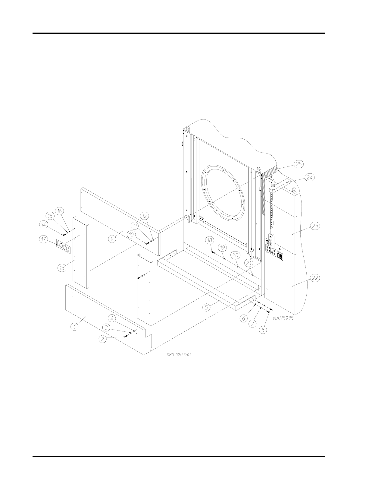
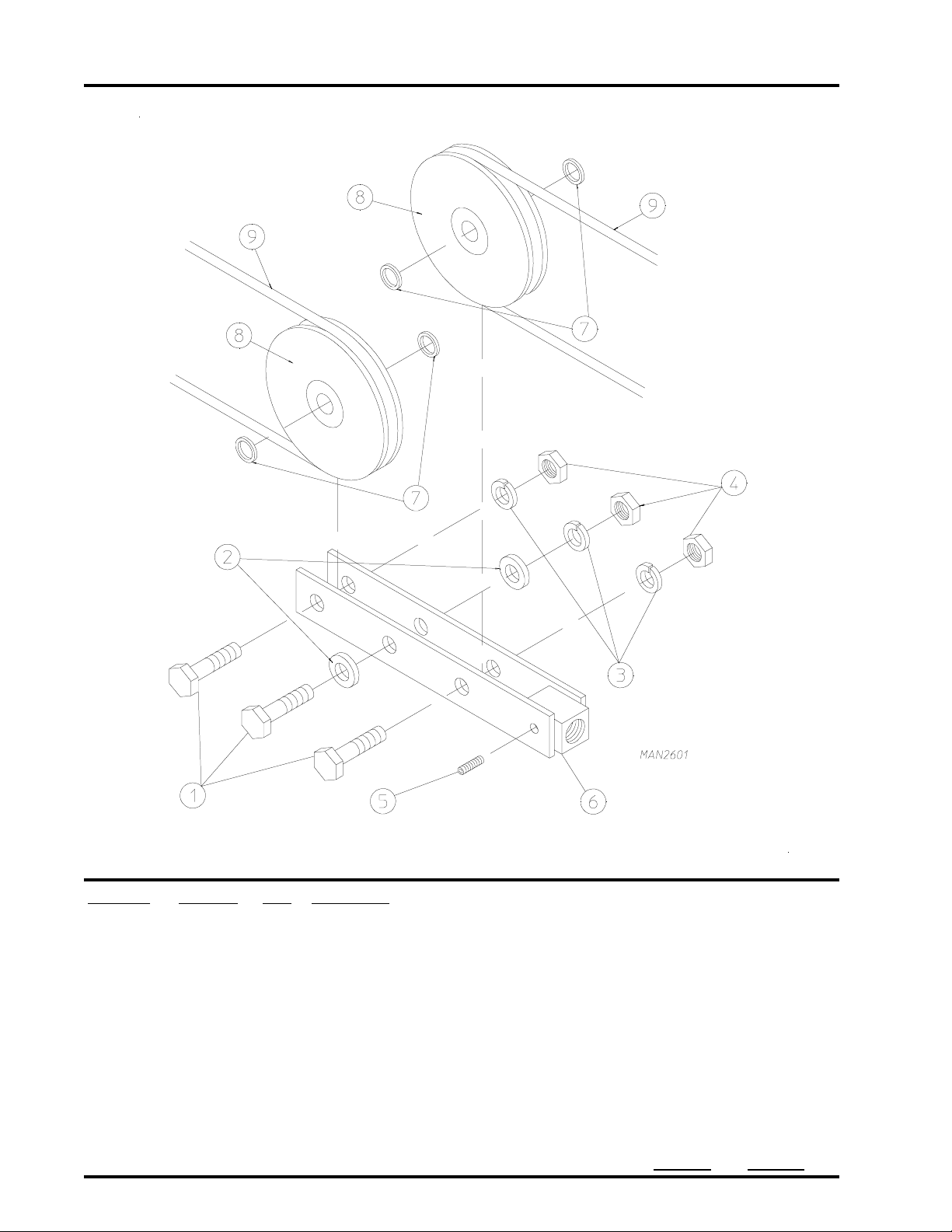
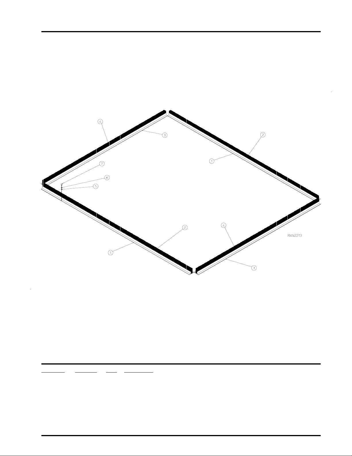
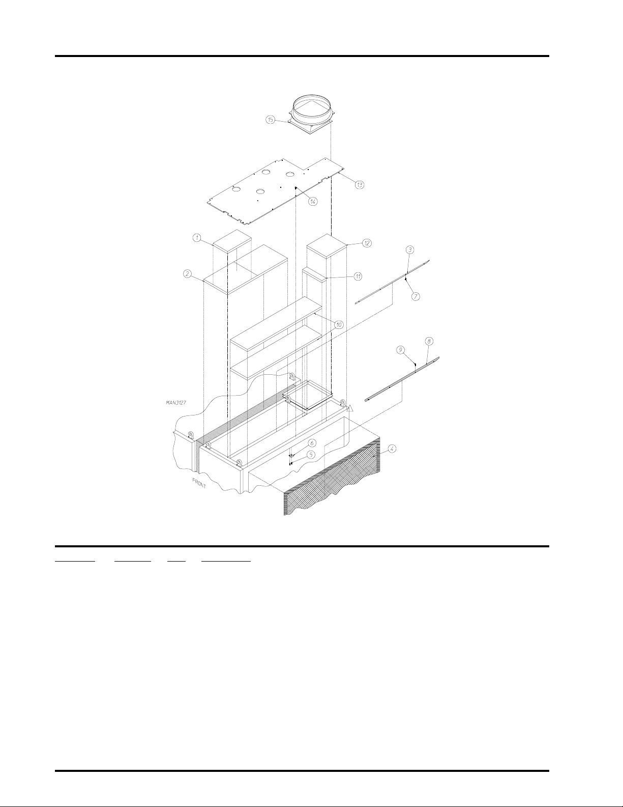
Front Safety Panel Assemblies
Illus. No. Part No. Qty. Description
1 820897 1 Rigid Bottom Safety Panel
2 150501 4 5/16-18 x 3/4” Tap Bolt
3 153002 4 5/16” Lock Washer
4 153001 4 5/16” Flat Washer
5 820636 1 Ste p B ar
6 153011 4 1/2” Flat Washer
7 153026 4 1/2” Lock Washer
8 150605 4 1/2-13 x 1-1/2” Tap Bolt
9 820594 1 Top Panel
10 150514 4 5/16-18 x 2-1/4” T ap Bolt
11 153002 4 5/16” Lock Washer
12 153001 4 5/16” Flat Washer
13 332018 2 Loading Door Side Panel
14 150501 16 5/16-18 x 3/4” Tap Bolt
15 153002 16 5/16” Lock Washer
16 153001 16 5/16” Flat Washer
17 123555 1 ADC Large Logo
870011 1 Double Tape Kit ONLY
-- 112373 - Milnor Large Logo
18 150600 7 3/8-16 x 1-1/2” Tap Bolt
19 153005 7 3/8” Lock Washer
20 153004 7 3/8” Flat Washer
21 154340 7 7/16” Beveled Washer
22 -------- 1 Control Door Assembly
(refer to Front Right Control Panel Assembly on
23 -------- 1 Character Panel Assembly
(refer to Character Panel Assembly on page 6)
24 -------- 1 Pendant Mounting Assembly
(refer to Pendant Mounting Assembly on page 7)
25 -------- 1 Console Brush Assembly
(refer to Console Brush Assembly on page 25)
5
page 8 and page 9)
Telephone: (508) 678-9000 Fax: (508) 678-9447
Page 8
6
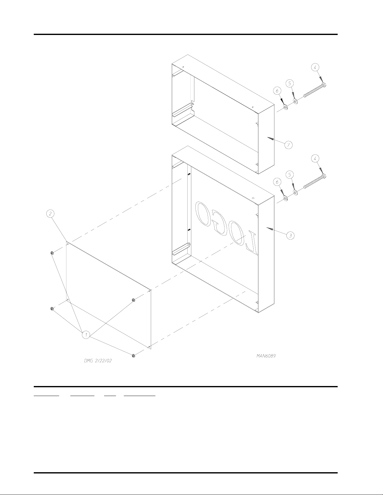
Character Panel Assembly
Illus. No. Part No. Qty. Description
1 152014 4 1/4-20 Free Spin Wash Nut
2 331959 1 Character Panel Backing Plate
3 846792 1 AD-464 Character Panel
846868 1 ML-460 Character Panel
4 150515 8 5/16-18 x 7-1/2” Hex Head Bolt
5 153002 8 5/16” Lock Washer
6 153001 8 5/16” Flat Washer
7 846793 1 Heat Co nsole Top Front Safety Panel
American Dryer Corporation 88 Currant Road / Fall River, MA 02720-4781
Page 9
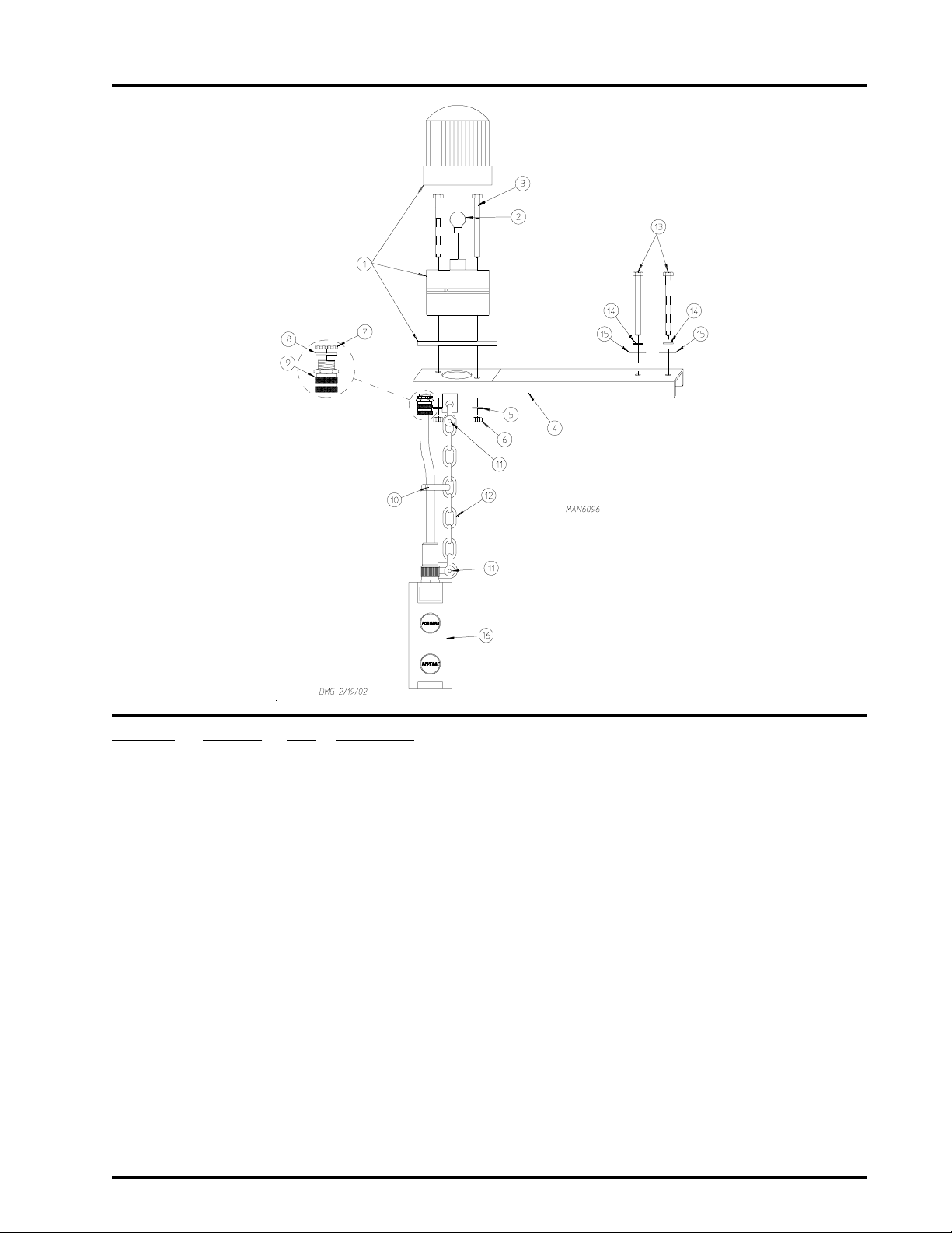
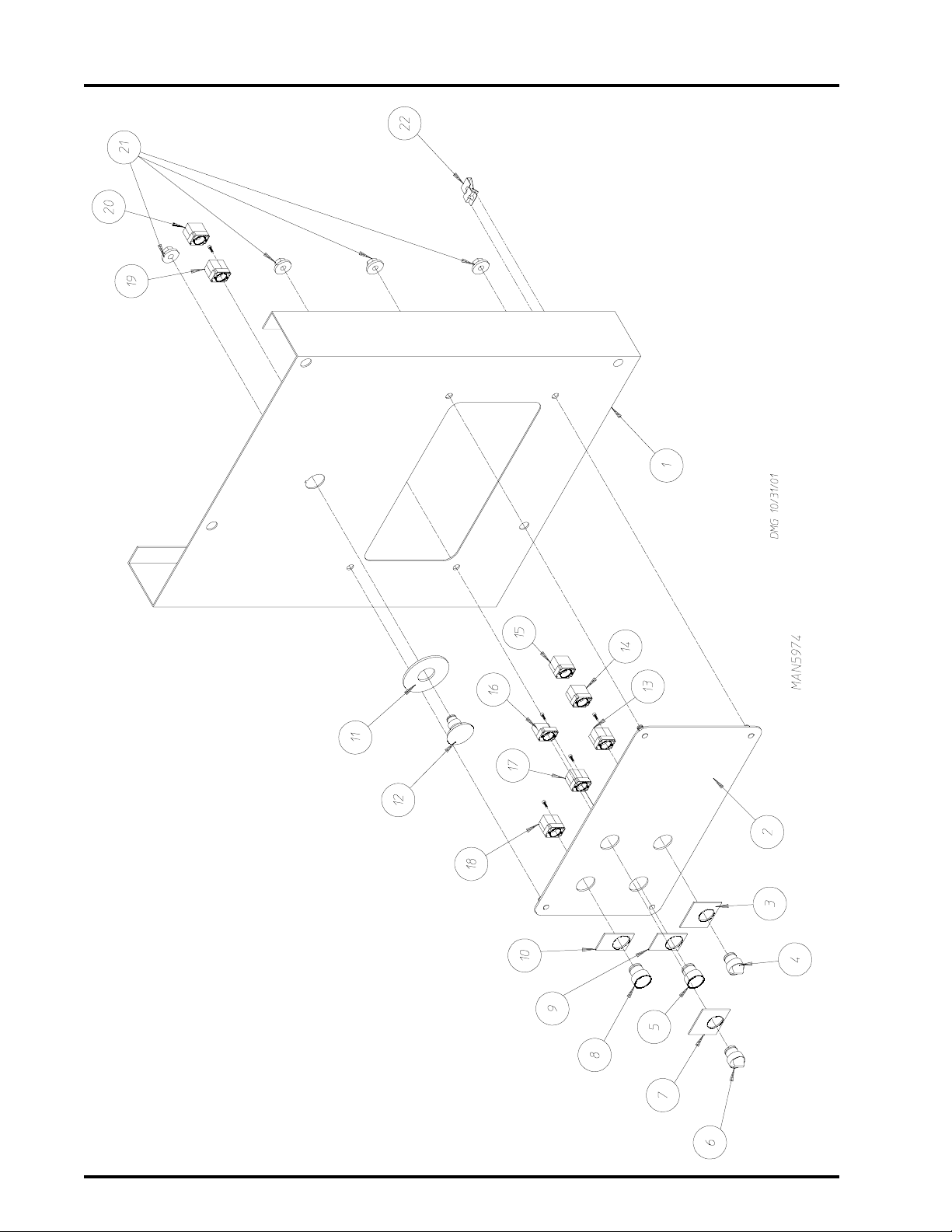
Pendant Mounting Assembly
7
Illus. No. Part No. Qty. Description
1 123222 1 Single Stage Orange Steady Light
2 123221 1 24V Replacement Lamp
3 150103 2 #8-32 x 3/4” Machine Screw
4 820545 1 Mounting Arm and Control
5 153012 2 # 8 Star Washer
6 152001 2 #8-32 Nut
7 120915 1 1/2” Lock Nut
8 120914 1 1/2” Sealing Washer
9 120655 1 1/2” N.P.T. Blue Straight Cord Grip
10 121508 6 Black Tie Wraps
11 108126 2 Anchor Shackle with Pin
12 108125 6 Chain (sold by the foot)
13 150526 2 1/4-20 x 3” Bolt
14 153007 2 1/4” Lock Washer
15 153018 2 1/4” Flat Washer
16 132409 1 Pendant Station with Cord Set
– 150535 2 #10-32 x 3/4” Flat Socket Head Cap Screw – Not Illustrated
– 153024 2 #10 Split Lock Washer – Not Illustrated
– 152008 2 #10-32 Hex Nut – Not Illustrated
– 102004 2 Compact Door Magnet – Not Illustrated
Telephone: (508) 678-9000 Fax: (508) 678-9447
Page 10
8
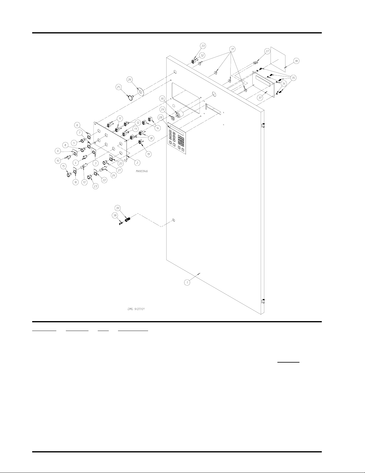
Front Right Control Panel Assembly
Illus. No. Part No. Qty. Description
1 817613 1 Front Right Control Door ONLY
2 --------- 1 Front Right Control Door Panel ONLY
(refer to Front Right Control Panel Assembly Chart on page 98)
3 122438 1 Load/Dry/Unload Nameplate
4 122361 1 3-Position Maintained Operator
5 123203 1 Black Push Button Operator
6 122415 1 Nameplate “Forward”
7 122416 1 Nameplate “Reverse”
8 123202 1 White Push Button Operator
9 122413 1 Tilt Off/Tilt On Nameplate
10 122360 1 2-Position Maintained Operator
1 1 132396 2 Mounting Base with Normally Opened (N.O.) and Normally Closed (N.C.)
Contact Block
12 132394 2 Mounting Base with Normally Opened (N.O.) Contact Block
American Dryer Corporation 88 Currant Road / Fall River, MA 02720-4781
Page 11

Front Right Control Panel Assembly (continued)
Illus. No. Part No. Qty. Description
13 132386 1 Normally Opened (N.O.) Contact Block
14 132387 4 Normally Closed (N.C.) Contact Block
15 123201 1 Green Lighted Push Button Operator
16 122410 1 Engraved Nameplate: ON
17 123212 1 24 V olt Lamp
18 132388 2 Normally Opened (N.O.) Contact Block with Direct Supply
19 132395 1 Mounting Base with Normally Closed (N.C.) Contact Block
20 122421 1 Engraved Nameplate: OFF
21 123204 1 Red Push Button Operator
22 122420 1 Sprinkler Stop Nameplate
23 123200 1 Amber Lighted Push Button Operator
24 123212 1 24 V olt Lamp
25 122351 1 “EMERGENCY STOP” (E-Stop) Operator
26 122419 1 Engraved “EMERGENCY STOP” (E-Stop) Label
27 121509 6 Tie Wrap Clips
28 112571 1 Phase 7 Keyboard (touch pad)
29 134018 1 Alarm Horn V olume Control
30 128967 1 80-90 Decibel Panel Mount Alarm Horn
31 152014 4 1/4-20 Hex Nut
32 132395 1 Mounting Base with Normally Closed (N.C.) Contact Block
33 132387 1 Normally Closed (N.C.) Contact Block
34 153010 4 # 6 Star Washer
35 150005 4 #6-32 x 1/4” Phillips Round Head Machine Screw
36 122426 1 Caution Label
37 883311 1 Phase 7 Display and Input/Output (I/O) Board Set with Suppression System
(for models mfd. as of April 24, 2002)
883312 1 Phase 7 Display Board with Suppression System
(for models mfd. as of April 24, 2002)
883313 1 Phase 7 Input/Output (I/O) Board with Suppression System
(for models mfd. as of April 24, 2002)
882894 1 Phase 7 Display and Input/Output (I/O) Board Set without
Suppression System
(for models mfd. prior to October 2000)
882896 1 Phase 7 Display Board without Suppression System
(for models mfd. between October 2000 and April 2002)
882895 1 Phase 7 Input/Output (I/O) Board without Suppression System
(for models mfd. between October 2000 and April 2002)
38 160140 1 ACE® XX4451 Key ONL Y
39 160050 1 ACE® Control Door Lock Less Key (keyed to #XX4451)
9
Telephone: (508) 678-9000 Fax: (508) 678-9447
Page 12
10
Front Right Cabinet Location Diagram
American Dryer Corporation 88 Currant Road / Fall River, MA 02720-4781
Page 13

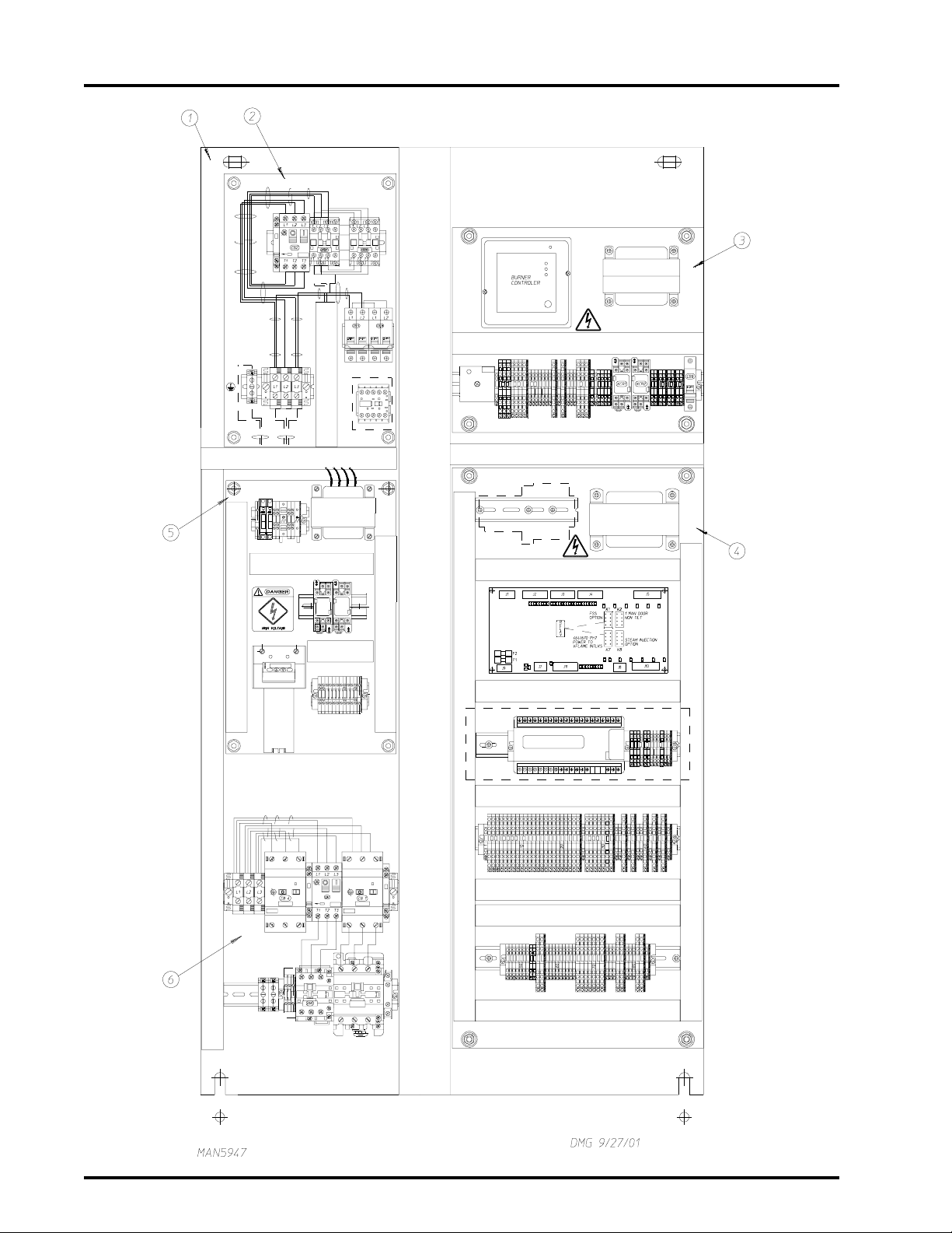
Front Right Cabinet Location Diagram
Illus. No. Part No. Qty. Description
1 -------- 1 Electrical Panel Assembly
2 -------- 1 Reversing Contactor Panel Assembly
(refer to Reversing Contactor Panel Assembly on page 12 and page 13)
3 -------- 1 Burner Control Panel Assembly
(refer to Burner Control Panel Assembly on page 14 and page 15)
4 -------- 1 Input/Output Board/PLC Panel Assembly
(refer to I/O Board and PLC Panel Assembly on page 16 and page 17)
5 --------- 1 Suppression System Lower Piping Assembly
(for models mfd. as of April 24, 2002)
(refer to Suppression System Lower Piping Assembly
on page 88 and page 89)
-------- 1 Suppression System Upper Piping Assembly
(for models mfd. as of April 24, 2002)
(refer to Suppression System Upper Piping Assembly
on page 86 and page 87)
-------- 1 Optional Sprinkler Panel Assembly
(for models mfd. prior to April 24, 2002)
(refer to Optional Sprinkler Control Panel on page 90 and page 91)
6 -------- 1 Main Power Junction Panel Assembly
(refer to Main Power Junction Panel Assembly
on page 18 and page 19)
11
Telephone: (508) 678-9000 Fax: (508) 678-9447
Page 14
12
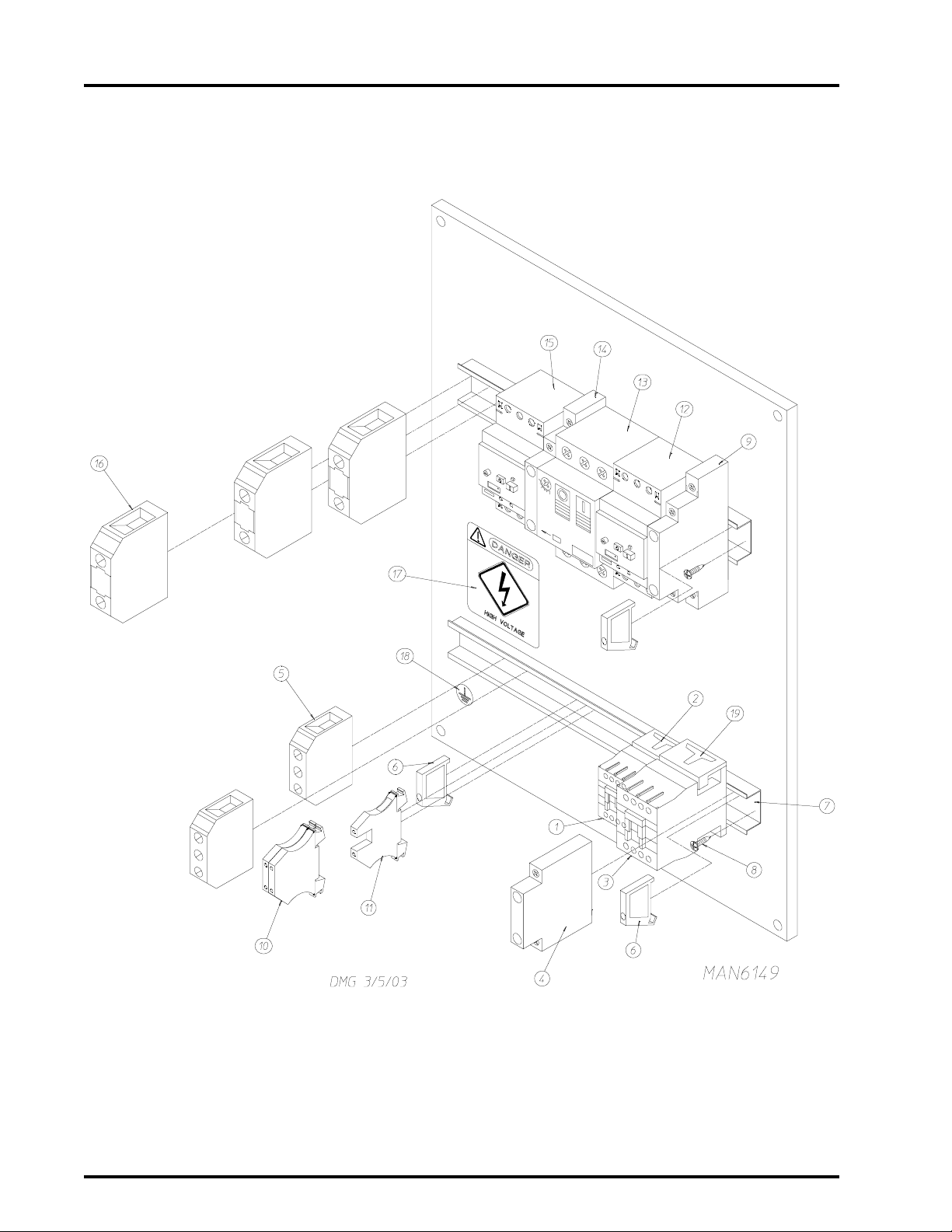
Reversing Contactor Panel Assembly
American Dryer Corporation 88 Currant Road / Fall River, MA 02720-4781
Page 15

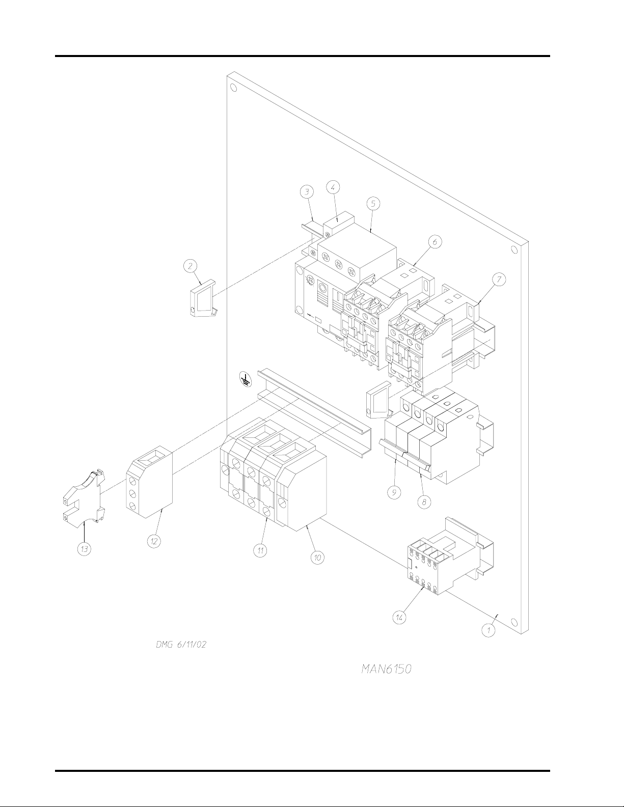
Reversing Contactor Panel Assembly
Illus. No Part No. Qty. Description
1 856301 1 Reversing Contactor Panel Assembly with Suppression System
(for models mfd. as of April 24, 2002)
856129 1 Reversing Contactor Panel Assembly with Sprinkler
(for models mfd. prior to April 24, 2002)
2 120765 2 End Stop
3 120768 * 35 x 15mm Din Rail
4 -------- 1 Auxiliary Contact Block
(refer to the Reversing Contactor Panel Assembly Chart on
5 -------- 1 Thermal Magnetic Breaker
(refer to the Reversing Contactor Panel Assembly Chart on
6 132437 2 Varistor
7 -------- 1 Reversing Contactor
(refer to the Reversing Contactor Panel Assembly Chart on page 97)
8 -------- 1 CB-#8 2-Pole Circuit Breaker
(refer to the Reversing Contactor Panel Assembly Chart on page 97)
9 -------- 1 CB-#5 2-Pole Circuit Breaker
(refer to the Reversing Contactor Panel Assembly Chart on page 97)
10 120770 2 End Bracket
11 120760 3 Terminal Block
12 120727 1 Ground Terminal Block
13 120750 1 Ground Terminal Block
14 132494 1 3 HP Control Relay (sprinkler option Only)
(for models mfd. prior to April 24, 2002)
13
page 97)
page 97)
* Sold by the inch.
Telephone: (508) 678-9000 Fax: (508) 678-9447
Page 16
14
Burner Control Panel Assembly
American Dryer Corporation 88 Currant Road / Fall River, MA 02720-4781
Page 17

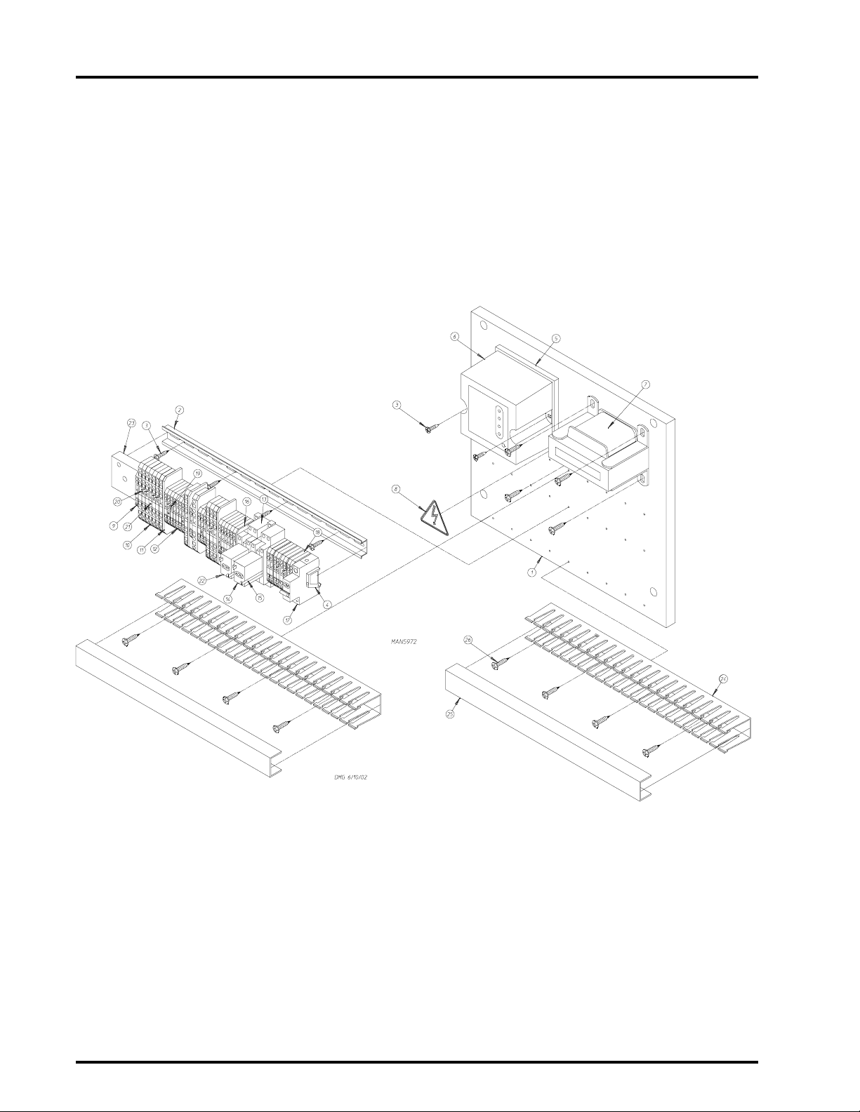
Burner Control Panel Assembly
Illus. No Part No. Qty. Description
1 367329 1 Front Right Burner Control Panel
2 120768 * 35 x 15mm Din Mounting Rail
3 150300 10 #10-16 x 1/2” Hex Washer TEK Screw
4 120765 1 End Stop
5 141066 1 Burner Control Base
6 141065 1 Burner Control (veri flame)
7 130060 1 Transformer (150-300VA)
8 122424 1 Power Warning Label (small)
9 120773 8 2-Position Green/Yellow Ground Block “G”
10 120778 12 4-Position Gray Line Block “L”
11 120801 4 Large Insulation for 4-Position Block
12 120771 17 2-Position Gray Line Block “L”
13 131410 2 Relay Base
14 131412 1 Relay 10-amp 24 VAC Coil
15 131411 4 Hold Downs
16 120776 5 Small Insulator for 2-Position Block
17 135516 1 8-amp Single-Pole Thermal Magnetic Breaker
18 120772 1 2-Position Blue Neutral Block “N”
19 120777 5 2-Position Terminal Block Jumper
20 120805 4 4-Position Terminal Block Jumper
21 120999 7 Decade Marking Tags (60-100)
22 131405 1 Relay 10-amp 120V Coil
23 131318 1 0.5 to 10-second “Delay On” Timer
24 121430 * 1” x 3” Slotted Gray Wall Wiring Duct
25 121422 * 1” Gray Wiring Duct Cover
26 150301 8 #8-18 x 7/16” Phillips Pan Head TEK Screw
– 121400 2 Universal Bushing – Not Illustrated
– 123000 2 Red Indicator Lamp – Not Illustrated
15
* Sold by the inch.
Telephone: (508) 678-9000 Fax: (508) 678-9447
Page 18
16
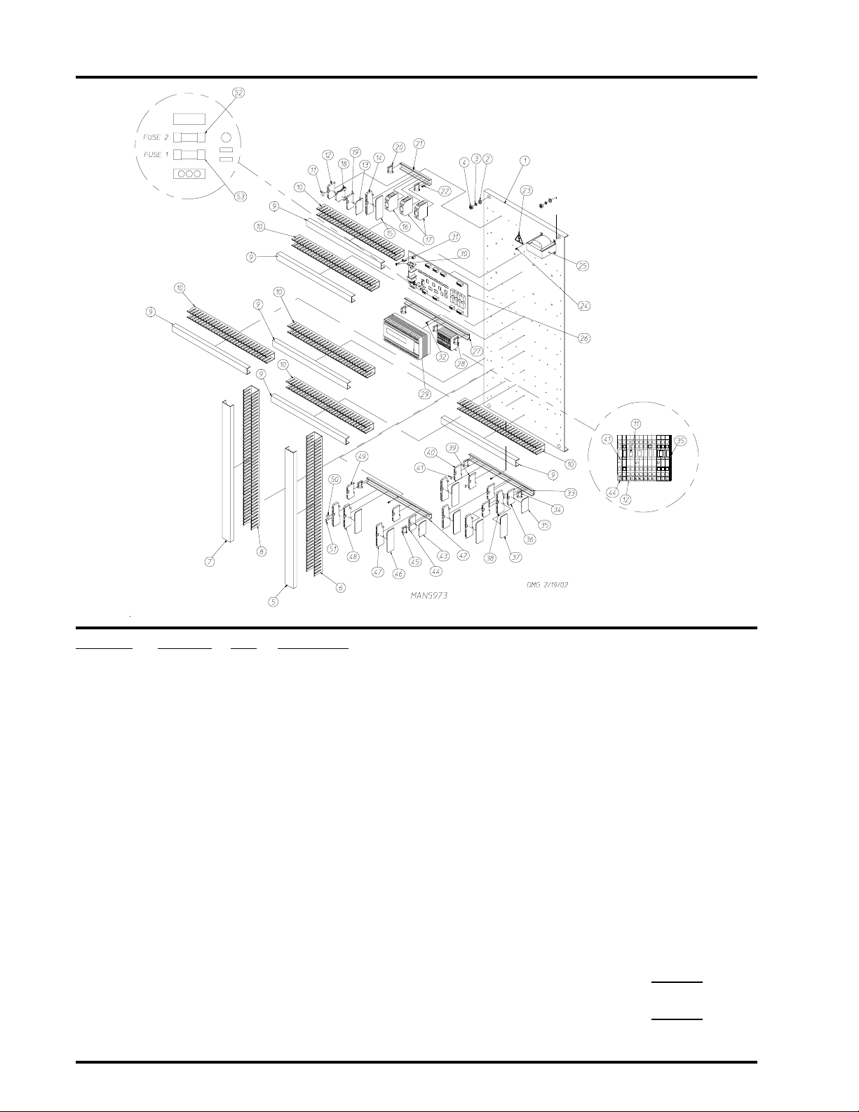
I/O Board and PLC Panel Assembly
Illus. No. Part No. Qty. Description
1 821833 1 Front Right Electrical Panel ONLY
2 150334 4 3/8” Flat Washer
3 153005 4 3/8” Lock Washer
4 152005 4 3/8-16 Hex Nut
5 121422 * 1” Wireway Cover
6 121430 * 1” x 3” Slotted Wall Wire Duct
7 121422 * 1” Wireway Cover
8 121430 * 1” x 3” Slotted Wall Wire Duct
9 121422 * 1” Wireway Cover
10 121430 * 1” x 3” Slotted Wall Wire Duct
1 1 120777 10 2-Position Terminal Block Jumper
12 120771 4 2-Position Gray Line Block
13 120776 6 Small Insulator for 2-Position Block
14 120778 2 4-Position Gray Line Block
15 120801 2 Large Insulator for 4-Position Block
16 -------- 1 Circuit Breaker #7
(refer to Front Right Control Panel Assembly Chart on page 98)
17 -------- 1 Circuit Breaker #6
(refer to Front Right Control Panel Assembly Chart on page 98)
18 120773 3 2-Position Green/Y ellow Ground Block
19 120772 2 2-Position Blue Neutral Block
American Dryer Corporation 88 Currant Road / Fall River, MA 02720-4781
Page 19

I/O Board and PLC Panel Assembly (continued)
Illus. No. Part No. Qty. Description
20 120765 2 Standard End Stop
21 120768 6 35 x 15mm Din Mounting Rail
22 150300 3 #10-16 x 1/2” Hex Washer TEK Screw
23 122424 1 Power Warning Label
24 150300 4 #10-16 x 1/2” Hex Washer TEK Screw
25 --------- 1 Transformer Assembly
(refer to Front Right Control Panel Assembly Chart on page 98)
26 883311 1 Phase 7 Display and Input/Output (I/O) Board Set with Suppression System
(for models mfd. as of April 24, 2002)
883313 1 Phase 7 Input/Output (I/O) Board with Suppression System
(for models mfd. as of April 24, 2002)
882895 1 Phase 7 Input/Output (I/O) Board without Suppression System
(for models mfd. between October 2000 and April 2002)
882494 1 Phase 7 Display and Input/Output (I/O) Board Set without
Suppression System
(for models mfd. prior to October 2000)
27 120768 28 35 x 15mm Din Mounting Rail
28 120765 2 Standard End Stop
29 883800 1 PLC
30 150005 4 #6-32 x 1/4” Phillips Round Head Machine Screw
31 153010 4 # 6 Star Washer
32 150300 4 #10-16 x 1/2” Hex Washer TEK Screw
33 120768 * 35 x 15mm Din Mounting Rail
34 120765 2 Standard End Stop
35 120776 1 Small Insulator for 2-Position Block
36 120771 21 2-Position Gray Line Block
37 120801 4 Large Insulator for 4-Position Block
38 120778 13 4-Position Gray Line Block
39 120773 3 2-Position Green/Yellow Ground Block
40 120772 1 2-Position Blue Neutral Block
41 401024 4 Marking Tags
42 120768 * 35 x 15mm Din Mounting Rail
43 120776 1 Small Insulator for 2-Position Block
44 120773 1 2-Position Green/Yellow Ground Block
45 120765 7 Large Insulator for 4-Position Terminal Block
46 120801 2 End Stops
47 120778 32 4-Position Gray Line Block
48 120779 3 4-Position Blue Neutral Block
49 120771 9 2-Position Gray Line Block
50 120805 10 4-Position Terminal Block Jumper
51 401024 4 Marking Tags
52 136109 1 2-amp 250v (fast acting) Fuse
53 136016 1 5-amp 250v (fast acting) Fuse
17
* Sold by the inch.
Telephone: (508) 678-9000 Fax: (508) 678-9447
Page 20
18
Main Power Junction Panel Assembly
American Dryer Corporation 88 Currant Road / Fall River, MA 02720-4781
Page 21

Main Power Junction Panel Assembly
Illus. No. Part No. Qty. Description
1 132440 1 2 HP Contactor
2 137029 1 Varistor
3 -------- 1 Fan Contactor
(refer to Main Power Junction Panel Assembly Chart on page 99)
4 132383 1 Auxiliary Contact Block
5 120727 2 Ground Terminal Block
6 120765 3 Standard End Stop
7 120768 * 35 x 15mm Din Rail
8 150300 8 #10-6 x 1/2 Hex Washer TEK Screw
9 132384 1 Auxiliary Contact Block
10 120758 2 Feed Thru Terminal Block
11 120750 1 Ground Terminal Block (for sprinkler option)
12 -------- 1 CB-1 Thermal Magnetic Breaker
(refer to Main Power Junction Panel Assembly Chart on page 99)
13 -------- 1 CB-9 Thermal Magnetic Breaker
(refer to Main Power Junction Panel Assembly Chart on page 99)
14 132389 1 Auxiliary Contact Block
15 -------- 1 CB-4 Thermal Magnetic Breaker
(refer to Main Power Junction Panel Assembly Chart on page 99)
16 120760 3 Terminal Block
17 114007 1 Danger High Voltage (HV) Label
18 112075 1 Ground Here Label
19 132485 1 Varistor
19
* Sold by the inch.
Telephone: (508) 678-9000 Fax: (508) 678-9447
Page 22
20
Rear Right Control Panel Assembly
American Dryer Corporation 88 Currant Road / Fall River, MA 02720-4781
Page 23

Rear Right Control Panel Assembly
2 Door Models ONLY
Illus. No. Part No. Qty. Description
1 883350 1 Right Rear Control Door ONL Y
2 -------- 1 Right Rear Door Control Panel
(refer to Rear Right Control Panel Assembly Chart on page 100)
3 122438 1 Load/Dry/Unload Nameplate
4 122361 1 3-Position Maintained Operator
5 123202 1 White Push Button Operator
6 122360 1 2-Position Maintained Operator
7 122413 1 Tilt Off/Tilt On Nameplate
8 123203 1 Black Push Button Operator
9 122416 1 Nameplate “Reverse”
10 122415 1 Nameplate “Forward”
11 122419 1 “EMERGENCY STOP” (E-Stop) Label
12 122351 1 “EMERGENCY STOP” (E-Stop) Operator
13 132394 1 Mounting Base with Normally Opened (N.O.) Contact Block
14 132386 1 Normally Opened (N.O.) Contact Block
15 132387 2 Normally Closed (N.C.) Contact Block
16 132394 1 Mounting Base with Normally Opened (N.O.) Contact Block
17 132396 1 Mounting Base with Normally Opened (N.O.) and Normally Closed (N.C.)
Contact Block
18 132396 1 Mounting Base with Normally Opened (N.O.) and Normally Closed (N.C.)
Contact Block
19 132395 1 Mounting Base with Normally Closed (N.C.) Contact Block
20 132387 1 Normally Closed (N.C.) Contact Block
21 152014 4 1/4-20 Wash Nut
22 121509 6 Tie Wrap Clips
21
Telephone: (508) 678-9000 Fax: (508) 678-9447
Page 24
22
Front Load Door Panel Assembly
American Dryer Corporation 88 Currant Road / Fall River, MA 02720-4781
Page 25

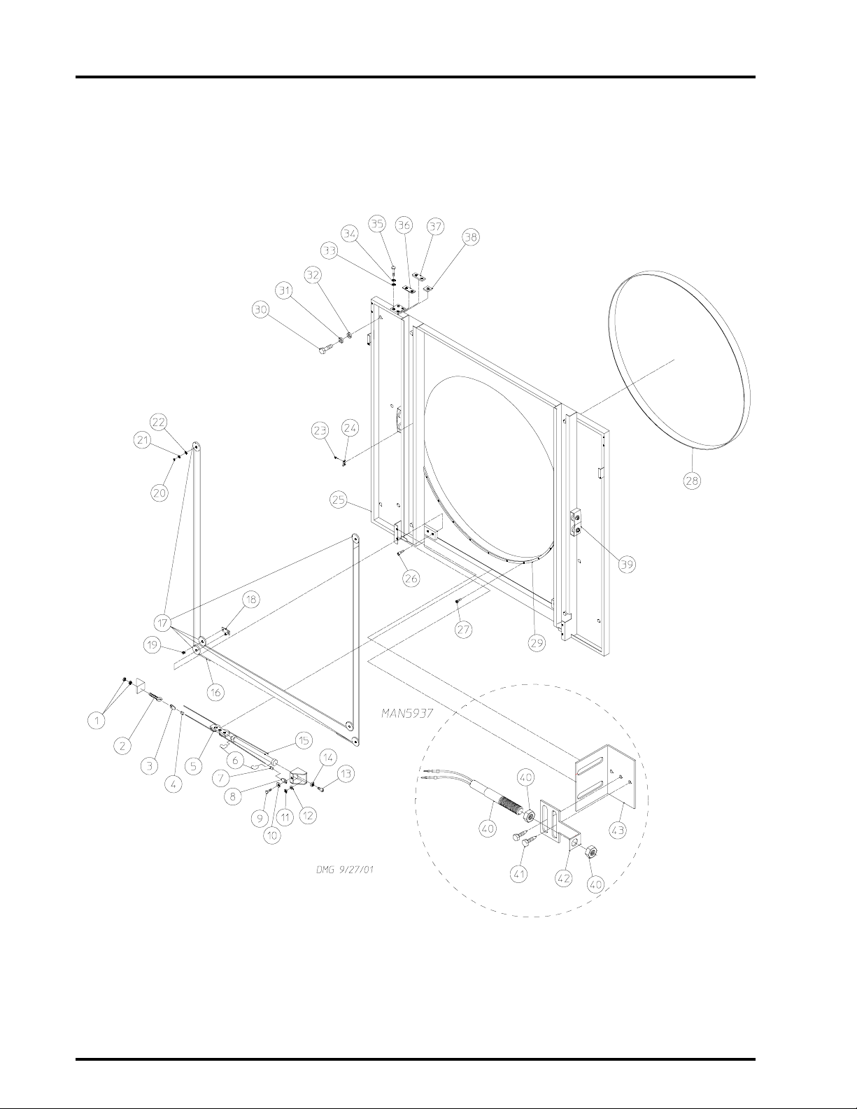
Front Load Door Panel Assembly
Illus. No. Part No. Qty. Description
1 152004 2 5/16-18 Hex Nut
2 170370 1 Turnbuckle
3 170373 1 Wire Rope Thimble
4 170371 1 Wire Rope Clamp
5 -------- 1 Cylinder Clevis
(refer to Cylinder Clevis Assembly on
6 143153 2 1/4” x 1/4” M.P.T. Elbow
7 170371 1 Wire Rope Clamp
8 170373 1 Wire Rope Thimble
9 150617 1 3/8-16 x 1” Hex Head Machine Bolt
10 153003 1 3/8” I.D. x 1-1/2” O.D. Fender Washer
11 152005 1 3/8-16 Hex Nut
12 153005 1 3/8” Lock Washer
13 150439 4 5/16-24 x 3/4” Socket Cap Screw
14 153002 4 5/16” Lock Washer
15 100554 1 2-1/2” Bore x 12-9/16” Door Piston
16 170372 1 Wire Rope (45 foot length)
17 101 1 90 6 Cable Pulley
18 820510 2 Pulley Shaft Plate
19 331522 2 Bushing for Cable Pulley
20 152005 4 3/8-16 Hex Nut
21 153005 4 3/8” Lock Washer
22 331524 4 Plain Bearing for Cable Pulley
23 154200 2 5/32” Pop Rivet
24 331909 1 Load Door Tab
25 820880 1 Front Panel ONLY
26 150441 2 1/4-20 x 1-3/8” Flat Head Socket Cap Screw
27 150412 9 #10-16 x 3/4” Phillips Round Head Crimptite Screw
28 116009 1 200” x 1-3/8” x 3/8” Basket (tumbler) Felt ONLY
881448 1 Basket (tumbler) Felt Replacement Kit
29 102385 1 Nylon Load Door Gasket
30 150617 8 3/8-16 x 1” Hex Head Bolt
31 153005 8 3/8” Lock Washer
32 153004 8 3/8” Flat Washer
33 153011 4 1/2” Flat Washer
34 153026 4 1/2” Lock Washer
35 150605 4 1/2-13 x 1-1/2” Tap Bolt
36 331789 4 Front Panel Hinge T op Shim
37 331786 2 Front Panel Hinge Top Spacer
38 820523 4 Bottom Hinge Spacer
39 820664 4 Basket (tumbler) Retaining Wheel Mount Assembly
40 882633 1 Magnetic Reed Switch
41 150309 2 #10-16 x 1/2” Hex Washer TEK Screw
42 367183 1 Rotational Sensor Bracket
43 367184 1 Switch Bracket
23
page 24)
Telephone: (508) 678-9000 Fax: (508) 678-9447
Page 26
24
Cylinder Clevis Assembly
Illus. No. Part No. Qty. Description
1 154313 3 12 x 4 4 m m Hex Head Cap Screw
2 153011 2 9/16” I.D. x 1-3/8” O.D. Flat Washer
3 153026 3 1/2” Lock Washer
4 152040 3 12 mm Hex Nut
5 154304 1 1/4-20 x 3/8” Knurled Socket Setscrew
6 820630 1 Cylinder Clevis Assembly Complete
(includes illus. nos. 1 through 8)
820517 1 Cylinder Clevis ONL Y
7 331524 4 Plain Bearing for Cable Pulley
8 1 0 1190 2 4” Cable Pulley
9 -------- 1 Wire Rope
(refer to Front Load Door Panel Assembly on page 22 and page 23)
American Dryer Corporation 88 Currant Road / Fall River, MA 02720-4781
Page 27
Console Brush Assembly
25
Illus. No. Part No. Qty. Description
1 170177 2 76-9/16” Brush Holder
2 170178 2 76-9/16” x 2-1/8” Wire Brush
3 170184 2 51-7/16” Brush Holder
4 170179 2 51-7/16” x 2-1/8” Wire Brush
5 153018 52 1/4” Flat Washer
6 153007 52 1/4” Lock Washer
7 150510 52 1/4-20 x 3/4” Hex Head Machine Bolt
Telephone: (508) 678-9000 Fax: (508) 678-9447
Page 28
26
T op Access Door Assembly
For Gas Models ONLY
Illus. No. Part No. Qty. Description
1 846769 1 Top Right Access Door Assembly
2 846771 1 Top Left Access Door Assembly
3 153007 11 1/4” Lock Washer
4 150512 11 1/4-20 x 1/2” Hex Head Machine Screw
5 116765 6 Top Access Door Insulation
6 346516 2 Top Access Door Cover
7 150301 16 #8-18 x 7/16” Phillips Pan Head TEK Screw
American Dryer Corporation 88 Currant Road / Fall River, MA 02720-4781
Page 29
T op Access Door Assembly
For S team Models ONL Y
27
Illus. No. Part No. Qty. Description
1 846821 1 Top Right Panel Assembly
2 846771 1 Top Left Panel Assembly
3 153007 11 1/4” Lock Washer
4 150512 11 1/4-20 x 1/2” Hex Head Machine Bolt
5 116765 6 Top Access Door Insulation
6 346516 2 Top Door Panel
7 150301 8 #8-18 x 7/16” Phillips Pan Head TEK Screw
8 150103 4 #8-32 x 3/4” Phillips Round Head Machine Screw
9 117705 1 Sliding Pad
10 331998 1 Sliding Pad Strip
11 153012 4 #8 S tar Washer
12 152001 4 #8-32 Hex Nut
Telephone: (508) 678-9000 Fax: (508) 678-9447
Page 30
28
Top Console Panel Assembly
For S team Models ONL Y
Illus. No. Part No. Qty. Description
1 116771 1 19” x 48” Steam Coil Top Insulation
2 116770 2 11-1/2” x 19” Next To Steam Coil Insulation
3 346587 1 Upper Angle Lint Screen Support
4 846813 1 Steam Coil Screen
5 150522 2 1/4-20 x 1/2” Hex Head TEK Screw
6 346612 1 Door Catch
7 150522 4 1/4-20 x 1/2” Hex Head TEK Screw
8 346586 1 Lower Angle Lint Screen Support
9 150522 4 1/4-20 x 1/2” Hex Head TEK Screw
10 116767 2 13-3/4” x 59-1/2” Center Console Insulation
11 116769 1 3-1/2” x 15-1/2” Small Steam Box Insulation
12 116768 2 15-1/2” x 16-1/4” Steam Box Insulation
13 346665 1 Steam Console Top
14 150522 17 1/4-20 x 1/2” Hex Head TEK Screw
15 846796 1 Transition Piece
American Dryer Corporation 88 Currant Road / Fall River, MA 02720-4781
Page 31

Top Console Left Hand Door Assembly
For Gas Models ONLY
29
Illus. No. Part No. Qty. Description
1 846783 1 Top Console Left Door Assembly Complete
(includes illus. nos. 1 through 6)
881363 1 Top Console Left Door Assembly with Gasket ONLY
(includes illus. nos. 1 and 6)
2 160205 1 2-Point Dead Bolt Latch
3 150512 4 1/4-20 x 1/2” Hex Head Machine Bolt
4 170217 1 Door Handle
5 153068 2 Brass Washer
6 102312 * Gray Extruded Gasket
* Sold by the foot
Telephone: (508) 678-9000 Fax: (508) 678-9447
Page 32

30
Top Console Left Hand Door Assembly
For S team Models ONL Y
Illus. No. Part No. Qty. Description
1 846828 1 Top Console Left Door Assembly Complete
(includes illus. nos. 1 through 6)
881489 1 Top Console Left Door Assembly with Gasket ONLY
(includes illus. nos. 1 and 6)
2 160205 1 2-Point Dead Bolt Latch
3 153068 2 Brass Washer
4 150512 4 1/4-20 x 1/2” Hex Head Machine Bolt
5 102312 * Gray Extruded Gasket
6 170217 1 Door Handle
* Sold by the foot.
American Dryer Corporation 88 Currant Road / Fall River, MA 02720-4781
Page 33

Lower Console Left Hand Door Assembly
For Gas Models ONLY
31
Illus. No. Part No. Qty. Description
1 846779 1 Lower Console Left Door Assembly Complete
(includes illus. nos. 1 through 9)
881365 1 Lower Console Left Door Assembly with Gasket ONLY
(includes illus. nos. 1 and 5)
2 160205 1 2-Point Dead Bolt Latch
3 153068 2 Brass Washer
4 102350 1 68-1/2” Door Gasket
5 102312 * Gray Extruded Gasket
6 846884 2 Combustion Blower Trim
7 153009 10 Star Washer
8 152008 10 #10-32 Hex Nut
9 170217 1 Door Handle
* Sold by the foot.
Telephone: (508) 678-9000 Fax: (508) 678-9447
Page 34

32
Lower Console Left Hand Door Assembly
For S team Models ONL Y
Illus. No. Part No. Qty. Description
1 846824 1 Lower Console Left Door Assembly Complete
(includes illus. nos. 1 through 6)
881490 1 Lower Console Left Door Assembly with Gasket ONLY
(includes illus. nos. 1 and 5)
2 160205 1 2-Point Dead Bolt Latch
3 153068 2 Brass Washer
4 150512 4 1/4-20 x 1/2” Hex Head Machine Bolt
5 102312 * Gray Extruded Gasket
6 152018 1 Door Handle
* Sold by the foot.
American Dryer Corporation 88 Currant Road / Fall River, MA 02720-4781
Page 35

Heat Console Right Hand Door Assembly
For S team Models ONL Y
33
Illus. No. Part No. Qty. Description
1 846830 1 Top Console Right Door Assembly Complete
(includes illus. nos. 1 through 3)
881488 1 Top Console Right Door Assembly with Gasket ONLY
(includes illus. nos. 1 and 3)
2 153068 2 Brass Washer
3 102312 * Gray Extruded Gasket
* Sold by the foot.
Telephone: (508) 678-9000 Fax: (508) 678-9447
Page 36

34
Lower Console Right Hand Door Assembly
For Gas Models ONLY
NOTE: Duplicate ALL components for Heat Console Right Hand Door Assembly – Not Illustrated.
Illus. No. Part No. Qty. Description
1 846781 1 Lower Console Right Door Assembly
(includes illus. nos. 1 through 3)
881364 1 Lower Console Right Door Assembly with Gasket ONLY
(includes illus. nos. 1 and 3 Only)
2 153068 2 Brass Hinge Washer
3 102312 * Gray Silicone Extruded Gasket
* Sold by the foot.
American Dryer Corporation 88 Currant Road / Fall River, MA 02720-4781
Page 37

Top Load Door Assembly
35
Illus. No. Part No. Qty. Description
1 820882 1 Top Load Door Assembly Complete
(includes illus. nos. 1 through 6)
820881 1 Top Load Door ONLY
2 116008 1 1-3/4” x 1/8” x 55” Load Door Felt
3 154200 10 5/32” Pop Rivet
4 331594 2 Bra ss Do or Ru nn e r
5 102215 1 Door Window
6 150440 4 5/16-18 x 1” Socket Cap Screw
- 170730 1 Silicone Adhesive (10.3 oz. cartridge)
Telephone: (508) 678-9000 Fax: (508) 678-9447
Page 38

36
Bottom Load Door Assembly
Illus. No. Part No. Qty. Description
1 820884 1 Bottom Load Door Assembly Complete
(includes illus. nos. 1 through 5)
820883 1 Bottom Load Door ONLY
2 154200 10 5/32” Pop Rivet
3 331594 2 Brass Door Runner
4 150440 4 5/16-18 x 1” Socket Cap Screw
5 116008 1 1-3/4” x 1/8” x 55” Load Door Felt
- 170730 1 Silicone Adhesive (10.3 oz. cartridge)
6 102102 1 Door Magnet
7 154200 1 5/32” Pop Rivet
American Dryer Corporation 88 Currant Road / Fall River, MA 02720-4781
Page 39

Optional Inlet Air Adaptor Assembly
37
Illus. No. Part No. Qty. Description
1 846838 1 Inlet Air Adaptor Assembly
2 346612 1 Door Catch
3 150522 3 1/4-20 x 1/2” Hex Head TEK Screw
– 346631 1 Base Side Cover – Not Illustrated
Telephone: (508) 678-9000 Fax: (508) 678-9447
Page 40

38
Optional Inlet Air Adapter Left Door Assembly
Illus. No. Part No. Qty. Description
1 846837 1 Left Door Assembly
2 170217 1 Door Handle
3 102315 * Silicone Rubber Extruded Gasket
170730 1 Silicone Adhesive (10.3 oz. cartridge)
4 160205 1 Door Latch
5 153068 2 Brass Washer
6 150512 4 1/4-20 x 1/2” Hex Head Machine Bolt
7 152018 2 1/4-28 Hex Nut
* Sold by the foot.
American Dryer Corporation 88 Currant Road / Fall River, MA 02720-4781
Page 41

Optional Inlet Air Adaptor Right Door Assembly
39
Illus. No. Part No. Qty. Description
1 846841 1 Right Door Assembly
2 153068 2 Brass Washer
3 102315 * Silicone Rubber Extruded Gasket
170730 1 Silicone Adhesive (10.3 oz. cartridge)
* Sold by the foot.
Telephone: (508) 678-9000 Fax: (508) 678-9447
Page 42

40
Left Side Panel Assembly
Illus. No. Part No. Qty. Description
1 346522 1 Lower Left Side Safety Panel
2 150514 4 5/16-18 x 2-1/4” Hex Head Bolt
3 153001 4 5/16” Flat Washer
4 153002 4 5/16” Lock Washer
5 846847 1 Middle Left Side Safety Panel
6 150514 2 5/16-18 x 2-1/4” Hex Head Bolt
7 153001 2 5/16” Flat Washer
8 153002 2 5/16” Lock Washer
9 846848 1 Upper Left Side Safety Panel
10 150514 4 5/16-18 x 2-1/4” Hex Head Bolt
1 1 153001 4 5/16” Flat Washer
12 153002 4 5/16” Lock Washer
13 346521 1 Basket (tumbler) Base Tilt Safety Panel
14 150501 6 5/16-18 x 3/4” Hex Head Tap Bolt
15 153001 6 5/16” Flat Washer
16 153002 6 5/16” Lock Washer
American Dryer Corporation 88 Currant Road / Fall River, MA 02720-4781
Page 43

Sail Switch Assembly
41
Illus. No. Part No. Qty. Description
1 105500 1 Sail Switch Actuator Rod
2 332689 1 Sail Switch Damper (flat)
3 154002 1 1/8” Push On Fastener
4 802800 1 Sail Switch Box with Cover and Bracket ONLY
(includes illus. nos. 4 and 8)
881376 1 Sail Switch Box Assembly Complete
(includes illus. nos. 1 through 4 and 6 through 10)
5 150300 2 #10-16 x 1/2” Hex Washer TEK Screw
6 150303 2 #4 x 3/4” Pan Head “A” Machine Screw
7 122404 1 Sail Switch ONL Y
8 802799 1 Sail Switch Box Cover and Bracket ONLY
9 150415 2 #10-16 x 1/2” Phillips Round Head Crimptite Screw
10 154004 1 Twin Speed Nut
Telephone: (508) 678-9000 Fax: (508) 678-9447
Page 44

42
RIGHT HAND LINT BASKET DOOR ASSEMBLY
Lint Basket Door Assembly
NOTE: Duplicate ALL components for Left Hand Lint Basket Door Assembly – Not Illustrated.
Illus. No. Part No. Qty. Description
1 846795 1 Lint Basket Door Assembly Complete
(includes illus. nos. 1 through 5)
2 153068 2 Brass Hinge Washer
3 170217 1 Large Dryer Door Handle
4 160009 1 Adjustable Cam
5 102312 * Gray Silicone Extruded Gasket
* Sold by the foot.
American Dryer Corporation 88 Currant Road / Fall River, MA 02720-4781
Page 45

Lint Drawer/Basket Assembly
43
Illus. No. Part No. Qty. Description
1 846965 2 Lint Drawer/Basket Assembly Complete
2 115995 * Felt Gasket
401010 1 Construction Mastic
3 122116 1 Lint Drawer Basket Switch ONLY
4 122605 2 4-Pin Socket Connector
5 122701 4 Socket Terminal ONLY
6 800264 2 Lint Drawer/Basket Switch Assembly Complete
(includes illus. nos. 3 through 7)
7 150301 4 #8-18 x 7/16” Phillips Pan Head TEK Screw
8 122700 4 Pin Terminal ONLY
9 122604 2 4-Pin Connector
10 150301 2 #8-18 x 7/16” Phillips Pan Head TEK Screw
11 346800 1 Lint Basket Felt Backer Plate
12 150301 5 #8-18 x 7/16” Phillips Pan Head TEK Screw
13 115989 1 Lint Basket Felt
14 346799 1 Lint Basket Felt Retaining Bar
15 150311 5 #10-16 x 3/4” Phillips Screw
* Sold by the inch.
Telephone: (508) 678-9000 Fax: (508) 678-9447
Page 46

44
Solid Back Panel Assembly
American Dryer Corporation 88 Currant Road / Fall River, MA 02720-4781
Page 47

Solid Back Panel Assembly
Illus. No. Part No. Qty. Description
1 152005 16 3/8-16 Hex Nut
2 153005 16 3/8” Lock Washer
3 153004 16 3/8” Flat Washer
4 150508 16 3/8-16 x 3/4” Hex Head Machine Bolt
5 116009 1 200” x 1-3/8” x 3/8” Basket (tumbler) Felt
6 331829 4 Solid Back Panel Cover
7 150621 16 5/16-18 x 1-1/2” T ap Bolt
8 153001 20 5/16” Flat Washer
9 153002 20 5/16” Lock Washer
10 150501 4 5/16-18 x 3/4” Tap Bolt
11 820855 1 Solid Back Panel Lower Guard
12 -------- 4 Basket (tumbler) Retaining Wheel Mount Assembly
(refer to Basket [Tumbler] Retaining Wheel Mount Assembly on
page 49)
13 150615 6 1/4-20 x 3/4” Tap Bolt
14 153018 6 1/4” Flat Washer
15 153007 6 1/4” Lock Washer
16 152002 6 1/4-20 Hex Nut
17 820523 4 Bottom Hinge Spacer
18 331786 2 Top Spacer Front Panel Hinge
19 153011 4 9/16” I.D. x 1-3/8” O.D. Flat Washer
20 153026 4 1/2” Lock Washer
21 150605 4 1/2-13 x 1-1/2” Tap Bolt
22 153002 4 5/16” Lock Washer
23 153001 4 5/16” Flat Washer
24 150501 4 5/16-18 x 3/4” Tap Bolt
25 820856 2 Lower Guard Mounting Channel
26 820603 1 Solid Back Panel
27 846846 2 Exhaust Insulation Panel
28 150225 12 5/16-18 x 3-1/2” Hex Head Machine Screw
29 153002 12 5/16” Lock Washer
30 153001 12 5/16” Flat Washer
31 846716 1 Basket (tumbler) ONLY
882009 1 Basket (tumbler) with Removable Panels/Perforated
846902 1 Basket (tumbler) with Perforated Ribs
(for fabric conditioning option Only)
32 881646 5 Removable Basket (tumbler) Panel/Perforated
33 150122 80 1/4-20 x 3/8” Stainless Steel Socket Button Head Screw
34 846947 1 Rotational Sensor Magnet Assembly
35 150309 4 #10-16 x 1/2” Hex Washer TEK Screw
45
Telephone: (508) 678-9000 Fax: (508) 678-9447
Page 48

46
Basket (T umbler) Drive Shaft Assembly
American Dryer Corporation 88 Currant Road / Fall River, MA 02720-4781
Page 49

Basket (T umbler) Drive Shaft Assembly
Illus. No. Part No. Qty. Description
1 180031 2 11” x 5” Drive Wheel Assembly with Hub
2 100712 2 1/2” x 1/2” x 3” Key
3 331760 2 Bearing Mount
4 880882 2 2” Pillow Block Bearing with Setscrews and Grease Fitting
5 153016 4 5/8” Flat Washer
6 150627 4 5/8-11 x 5” Hex Head Bolt
7 153016 2 5/8” Flat Washer
8 153015 4 5/8” Lock Washer
9 152010 4 5/8-11 Hex Nut
10 101022 1 2” Bore Tapered Bushing
11 101019 1 Taper Bushed Speed Reducer
12 154395 1 Gear Reducer Turnbuckle
13 150508 2 3/8-16 x 3/4” Bolt
14 153005 2 3/8” Lock Washer
15 153004 2 3/8” Flat Washer
16 10 1176 1 2B x 5.6 Pulley
17* 100118 2 5L-310 V-Belt (for 60 Hz models)
100119 2 5L-320 V-Belt (for 50 Hz models)
18 100709 1 3/8” x 3/8” x 2” Key
19 101196 1 SDS x 1-5/8” Bushing with Setscrew
20 346510 1 2” x 79-1/16” Drive Shaft
21 332838 2 Basket (tumbler) Bearing Spacer
22 150629 2 1/2-13 x 3-1/2” Hex Head Bolt
23 153026 2 1/2” Lock Washer
24 152011 2 1/2-13 Hex Nut
25 101191 2 2” Bore Tapered Bushing
26 101171 2 Lock Collar - 2” Bore
47
* Replace in matched sets (both belts).
Telephone: (508) 678-9000 Fax: (508) 678-9447
Page 50

48
Basket (T umbler) Idler Shaft Assembly
Illus. No. Part No. Qty. Description
1 180031 2 11” x 5” Drive Wheel Assembly with Hub
2 100712 2 1/2” x 1/2” x 3” Key
3 331760 2 Bearing Mount
4 880882 2 2” Pillow Block Bearing with Setscrews and Grease Fitting
5 153016 4 5/8” Flat Washer
6 150627 4 5/8-11 x 5” Hex Head Bolt
7 153016 2 5/8” Flat Washer
8 153015 4 5/8” Lock Washer
9 152010 4 5/8-11 Hex Nut
10 346510 1 2” x 79-1/16” Drive Shaft
1 1 332838 2 Basket (tumbler) Bearing Spacer
12 150629 2 1/2-13 x 3-1/2” Hex Head Bolt
13 153026 2 1/2” Lock Washer
14 152011 2 1/2-13 Hex Nut
15 101191 2 2” Bore Tapered Bushing
16 101171 2 Lock Collar - 2” Bore
American Dryer Corporation 88 Currant Road / Fall River, MA 02720-4781
Page 51

Basket (T umbler) Retaining Wheel Mount Assembly
49
Illus. No. Part No. Qty. Description
1 152005 2 3/8-16 Hex Nut
2 153005 2 3/8” Lock Washer
3 180029 2 Retaining Wheel
4 153062 4 5/16” x 7/8” x 1/4” Spherical Washer
5 153004 2 3/8” Flat Washer
6 150438 2 3/8-16 x 3-1/4” Hex Head Machine Bolt
Telephone: (508) 678-9000 Fax: (508) 678-9447
Page 52

50
Drive Motor Assembly
Illus. No. Part No. Qty. Description
1 100704 1 1/4” x 1/4” x 1-3/4” Key
2 1 0 1144 1 SH x 1-1/8” Bushing
3 1 01187 1 2B x 3.6 Pulley (for 60 Hz models Only)
10 1195 1 2B x 4.4 Pulley (for 50 Hz models Only)
4* 100118 2 5L-310 V -Belt (for 60 Hz models Only)
100119 2 5L-320 V-Belt (for 60 Hz Models Only)
100138 2 A30 V-Belt (motor to basket [tumbler] drive shaft) (for 50 Hz Models Only)
5** 181023 1 7.5 HP 50/60 Hz 1800 RPM Drive Motor
6 150508 4 3/8-16 x 3/4” Hex Head Bolt
7 153005 4 3/8” Lock Washer
8 153004 4 3/8” Flat Washer
* Replace in matched sets (both belts).
** Specify voltage when ordering.
American Dryer Corporation 88 Currant Road / Fall River, MA 02720-4781
Page 53

Basket (T umbler) Brush Holder Assembly
51
Illus. No. Part No. Qty. Description
1 170189 1 62-1/2” Wire Brush
2 170188 1 62-1/2” Aluminum Basket (tumbler) Brush Holder
3 346537 1 Basket (tumbler) Brush Mounting Bracket
4 150510 1 1 1/4-20 x 3/4” Hex Head Machine Bolt
5 153007 1 1 1/4” Lock Washer
6 153018 1 1 1/4” Flat Washer
7 152002 15 1/4-20 Hex Nut
8 153018 16 1/4” Flat Washer
9 153007 4 1/4” Lock Washer
Telephone: (508) 678-9000 Fax: (508) 678-9447
Page 54

52
Basket (T umbler) Rotational Sensor Switch Assembly
Illus. No. Part No. Qty. Description
1 333152 1 Rotational Sensor Bracket
2 882633 1 Rotational Sensor Proximity Switch
3 150309 2 #10-16 x 1/2” Hex Head TEK Screw
American Dryer Corporation 88 Currant Road / Fall River, MA 02720-4781
Page 55

Front/Rear Tilting Switch
53
Illus. No. Part No. Qty. Description
1 152001 4 #8-32 Hex Nut
2 153012 4 #8 S tar Washer
3 153000 4 #8 Flat Washer
4 331911 1 Tilt Switch Bracket
5 120655 1 Blue Cord Grip Connector
6 122367 1 Limit Switch Body
7 122365 1 Limit Switch ONL Y
8 150109 4 #8-32 x 2” Phillips Round Head Machine Screw
9 122369 1 Roller Lever Arm
Telephone: (508) 678-9000 Fax: (508) 678-9447
Page 56

54
T ilting Piston Assembly
Illus. No. Part No. Qty. Description
1 100563 1 6” Bore x 19” Stroke Cylinder with Clevis Pin
100433 1 6” Bore x 15” Stroke Cylinder with Clevis Pin (optional)
100488 1 Clevis Pin ONLY
2 143221 1 3/8” Brass Union Tee
3 143120 10 3/8” O.D. Poly-Flo Tubing (sold by the foot)
4 143298 2 3/8” x 90° Compression Elbow
5 143299 2 3/8” Tube Insert
6 100442 1 Rod Eye
7 154333 2 1/4-20 x 1” Cup Point Setscrew
8 102383 2 Cylinder Pin Bumper
9 150435 4 3/8-16 x 3” Socket Cap Screw
10 346491 1 1-3/8” Clevis Pin
11 100484 1 Rod Clevis
12 153034 1 1-1/4” Flat Washer
13 153036 1 1-1/4” Lock Washer
14 150516 1 1-1/4-12 x 2” Hex Head Bolt
American Dryer Corporation 88 Currant Road / Fall River, MA 02720-4781
Page 57

Piston Post Assembly
For One-W ay Tilt Models ONLY
55
Illus. No. Part No. Qty. Description
1 846763 1 Piston Bar
2 100448 1 1” Pivot Pin
3 100442 1 Rod Eye
4 154333 2 1/4-20 x 1” Setscrew
5 150435 4 3/8-16 x 3” Socket Cap Screw
6 102383 2 Cylinder Pin Bumper
7 346491 1 1-3/8” Clevis Pin
8 100484 1 Clevis Block
9 153034 1 1-1/4” Flat Washer
10 153036 1 1-1/4” Lock Washer
11 150516 1 1-1/4-12 x 2” Hex Head Bolt
Telephone: (508) 678-9000 Fax: (508) 678-9447
Page 58

56
Standard Main Fan Blower Assembly
American Dryer Corporation 88 Currant Road / Fall River, MA 02720-4781
Page 59

Standard Main Fan Blower Assembly
Illus. No. Part No. Qty. Description
1 152011 4 1/2-13 Hex Nut
2 153014 4 1/2” Flat Washer
3 153026 4 1/2” Lock Washer
4 181021 1 25 HP 3ø 50/60 Hz Motor
5 181 104 1 284T Frame Slide Motor Base
6 153014 4 1/2” Flat Washer
7 153026 4 1/2” Lock Washer
8 150605 4 1/2-13 x 1-1/2” Tap Bolt
9 100709 1 3/8” x 3/8” x 2” Key
10 101214 1 SK x 1-7/8” Bushing
11 101176 1 2B x 5.6 Pulley (for 60 Hz models Only)
10 1189 1 2B x 8.0 Pulley (for 50 Hz models Only)
12 10 115 4 1 SK x 1-3/4” Bushing
13 10 1145 1 2B x 11.0 Pulley
14* 100122 2 BX 84 V-Belt
15 346402 1 Blower Shaft ONLY
16 100710 2 3/8” x 3/8” x 3” Key
17 100239 2 1-3/4” Pillow Block Bearing
18 150606 4 1/2-13 x 2” Tap Bolt
19 153026 4 1/2” Lock Washer
20 153011 4 1/2” Flat Washer
21 100816 2 1-3/4” E-Clip
22 100661 1 22-1/4” Blower Wheel
23 153071 1 Fan Washer
24 152053 2 3/4-16 Left Hand Jam Nut
25 846801 1 Belt Guard ONLY
26 150301 1 #8-18 x 7/16” Phillips Pan Head TEK Screw
27 150512 2 1/4-20 x 1/2” Hex Head Machine Bolt
28 153007 2 1/4” Lock Washer
29 153018 2 1/4” Flat Washer
30 152002 2 1/4-20 Hex Nut
57
* Replace in matched sets (both belts).
Telephone: (508) 678-9000 Fax: (508) 678-9447
Page 60

58
Optional Dirty Fan Blower Assembly
American Dryer Corporation 88 Currant Road / Fall River, MA 02720-4781
Page 61

Optional Dirty Fan Blower Assembly
Illus. No. Part No. Qty. Description
1 181006 1 25 HP 3600 RPM 50/60 Hz 3ø Motor
2 100249 2 2” Pillow Block Bearing Air Handling
3 101145 1 2B x 11 SK Sheave
4 101210 1 SK x 2 Bushing with Setscrew
5 101238 1 2 B x 8.6 SK Sheave
6 367176 1 Impellor Shaft
7 101237 1 SK x 1.625 Bushing
8 153071 1 Fan Washer
9 100665 1 Impellor Wheel
10 152053 2 3/4-16 Left-Hand Hex Nut
11 153026 12 1/2 Standard Lock Washer
12 153011 8 9/16” ID 1-3/8” OD Flat Washer
13 150606 8 1/2-13 x 2” Tap Bolt
14 100129 2 BX-94 Belt
15 181007 1 256T Frame Slide Motor Base
16 100709 1 3/8” x 3/8” x 2” Key
17 100819 2 2” C Clip
18 100703 1 0.5” x 0.5” x 2” Key
59
Telephone: (508) 678-9000 Fax: (508) 678-9447
Page 62

60
Combustion Air Assembly
For Gas Models ONLY
American Dryer Corporation 88 Currant Road / Fall River, MA 02720-4781
Page 63

Combustion Air Assembly
For Gas Models ONLY
Illus. No. Part No. Qty. Description
1 181005 1 1-1/2 HP Motor
2 112093 1 “Arrow” Decal
3 846735 1 Combustion Air Mounting Assembly
4 153004 6 3/8” Flat Washer
5 153005 6 3/8” Lock Washer
6 150508 6 3/8-16 x 3/4” Hex Head Bolt
7 846879 1 Combustion Air Duct Assembly
8 150501 4 5/16-18 x 3/4” Hex Head Bolt
9 153002 4 5/16” Lock Washer
10 153005 4 3/8” Lock Washer
11 150508 4 3/8-16 x 3/4” Hex Head Bolt
12 100659 1 Blower Wheel
13 153050 1 1/2” Flat Washer
14 152006 2 1/2-20 Jam Nut
15 846736 1 Inlet Ring Assembly
16 150301 1 #8-18 x 7/16” Phillips Pan Head TEK Screw
17 143502 1 8” x 90º Galvanized Elbow
18 150301 1 #8-18 x 7/16” Phillips Pan Head TEK Screw
19 846743 1 Combustion Air Filter Box Assembly
20 346457 1 Combustion Air Damper
21 152002 4 1/4-20 Hex Nut
22 153007 4 1/4” Lock Washer
23 152002 4 1/4-20 Hex Nut
24 846744 1 Combustion Air Lint Screen Assembly
25 150301 1 #8-18 x 7/16” Phillips Pan Head TEK Screw
61
Telephone: (508) 678-9000 Fax: (508) 678-9447
Page 64

62
Combustion Air Switch Assembly
For Gas Models ONLY
Illus. No. Part No. Qty. Description
1 820864 1 Combustion Air Dif ferential Switch Assembly Complete
(includes illus. nos. 1 through 13)
136993 1 Combustion Air Dif ferential Switch ONLY
2 150501 1 5/16-18 x 3/4” T ap Bolt
3 153002 1 5/16” Lock Washer
4 152002 2 1/4-20 Hex Nut
5 153007 2 1/4” Lock Washer
6 150510 2 1/4-20 x 3/4” Hex Head Machine Bolt
7 143152 2 1/4” x 1/8” M.P.T. Straight Brass Connector
8 331471 1 Combustion Air Switch Bracket
9 143151 1 1/4” to 3/8” M.P.T. Brass Elbow
10 143257 1 3/8” F.P.T. Brass Bulkhead Adaptor
1 1 150301 1 #8-18 x 7/16” Phillips Pan Head TEK Screw
12 154005 1 Tinnerman Clip
13 882157 4 1/4” Aluminum Tubing (sold by the foot)
American Dryer Corporation 88 Currant Road / Fall River, MA 02720-4781
Page 65

Burner Assembly
For Gas Models ONLY
63
Illus. No. Part No. Qty. Description
1 141127 1 280 RAH Air-Heat Burner
2 150508 4 3/8-16 x 3/4” Hex Head Bolt
3 153004 4 3/8” Flat Washer
4 331779 2 Burner Box Mounting Bracket
5 1 4117 9 1 Spark Plug
6 1 41 1 7 8 2 Flame Rod
Telephone: (508) 678-9000 Fax: (508) 678-9447
Page 66

64
High/Low Fire Gas Piping Assembly
Illus. No. Part No. Qty. Description
1 142552 7 2” x 3” Black Iron Nipple
2 142606 1 2 ” x 1-1/2” x 2” Black Iron Tee
3 142827 2 1-1/2” x 2-1/2” Large Nipple, Bi
4 142603 1 1-1/2” Black Iron Union
5 142506 3 1/2” Street Elbow, Bi
6 142707 9 1/2” x 1-1/2” Large Nipple, Bi
7 141059 1 1/2” N.P.T. Manual Shutoff Valve
8 141167 1 1/2” N.P.T. Pilot Gas Regulator
9 141067 2 1/2” N.P.T. Pilot Gas Solenoid Valve
10 143140 1 Elbow 3/8” Flare x 3/8” M.P.T.
1 1 141310 1 1” PSIG - 2” N.P.T. Gas Regulator
12 14 116 9 2 Manual Shutoff Valve with Tap
13 143262 1 3/8” to 1/4” Brass Reducing Bushing
American Dryer Corporation 88 Currant Road / Fall River, MA 02720-4781
Page 67

High/Low Fire Gas Piping Assembly (continued)
Illus. No. Part No. Qty. Description
14 142517 1 2” Close Nipple
15 142930 1 1-1/2” x 1/2” Reducing Coupling
16 142592 3 2” x 4” Long Nipple, Bi
17 142542 2 2” Union
18 142704 1 1/2” x 4” Bi Nipple
19 141063 1 Hi/Low Gas Pressure Switch
20 143286 1 3/8” Tube x 1/4” M.P.T., 45° Flare Male Connector
21 143268 1 1/8” Brass Street Elbow
22 142716 1 1/2” x 6” Bi Nipple
23 141127 1 280 RAH Air Heat Burner Position #4
24 143141 1 3/8” Tube x 1/4” M.P.T., 90° Elbow, 45° Flare
25 143148 8 3/8” Stainless Steel Tubing (sold by the foot)
26 153016 1 5/8” Flat Washer
27 331376 1 Hi/Low Pressure Switch Bracket
28 143144 8 Long Forged Nut, 45° Flare
29 14 1164 1 1/2” Adjusted Orifice Pilot Gas Cock
30 143261 2 1/2” to 3/8” Brass Reducing Bushing
31 142820 3 1/2” Tee, Bi
32 168205 1 0 ” t o 15” Water Gauge
33 141032 1 Gas V alve Train Assembly
34 154352 2 2” Pipe U-Bolt
35 820823 2 Mounting Bracket, Gas Piping
36 152005 4 5/16-16 Hex Nut
37 153005 4 3/8” Lock Washer
38 153004 4 3/8” Flat Washer
39 142451 1 2” 90° Elbow
40 142600 2 1/2” Black Union
41 150522 4 1/4-20 x 1/2” Hex Head Washer TEK Screw
42 143257 1 3/8” F.P.T. Brass Bulkhead Connector
43 143142 3 3/8” N.P.T. x 3/8” Tube Male Connector
44 141307 1 Module 220/6 Eclipse-Dungs Gas V alve
45 141086 1 Closed Position Indicator Switch
46 142925 2 2 ” x 2” x 1/2” Tee, Bi
47 142747 2 1/2” Pipe Plug, Bi
65
Telephone: (508) 678-9000 Fax: (508) 678-9447
Page 68

66
Burner Box Housing Assembly
For Gas Models ONLY
Illus. No. Part No. Qty. Description
1 846731 1 Burner Box Housing Door
2 150501 4 5/16-18 x 3/4” T ap Bolt
3 153002 4 5/16” Lock Washer
4 153001 4 5/16” Flat Washer
5 116227 1 Burner Box Door Insulation
6 846731 1 Front Burner Box Housing
7 346437 1 Rear Insulation Cover
8 116228 1 Burner Box Housing Insulation
9 150600 5 3/8-16 x 1-1/2” Tap Bolt
10 153005 5 3/8” Lock Washer
1 1 153005 5 3/8” Lock Washer
12 153004 5 3/8” Flat Washer
13 150508 5 3/8-16 x 3/4” Hex Head Bolt
14 331851 5 Burner Box Housing Anchor Bracket
15 846728 1 Burner Box Housing
16 846732 1 Burner Box Housing Top Panel
17 153018 8 1/4” Flat Washer
18 153007 8 1/4” Lock Washer
19 150510 8 1/4-20 x 3/4” Hex Head Machine Screw
American Dryer Corporation 88 Currant Road / Fall River, MA 02720-4781
Page 69

Door Switch Assembly
67
Illus. No. Part No. Qty. Description
1 367183 1 Side Door Switch Mount
2 367184 1 Side Door Switch Guard
3 882633 1 Reed Switch Assembly
4 150309 2 #10-16 x 1/2” Hex Head TEK Crimptite Screw
Telephone: (508) 678-9000 Fax: (508) 678-9447
Page 70

68
Phase 7 Probe Bracket Assembly
Illus. No. Part No. Qty. Description
1 867122 1 Sensor Bracket
2 130202 1 235º Manual Reset Exhaust Hi-Limit
3 880251 1 1/4” Temperature Sensor Probe Kit
4 847801 1 Probe Door
American Dryer Corporation 88 Currant Road / Fall River, MA 02720-4781
Page 71

Cool Down Damper Assembly
For S team Models ONL Y
69
Illus. No. Part No. Qty. Description
1 150103 4 #8-32 x 3/4” Phillips Round Head Machine Screw
2 117705 1 Sliding Pad
3 331998 2 Sliding Pad Strip
4 153012 4 #8 S tar Washer
5 152001 4 #8-32 Hex Nut
6 820648 1 Lifting Linkage Assembly
7 100219 2 1-1/4” Diameter Pillow Block Bearing
8 150600 8 3/8-16 x 1-1/2” Hex Head Bolt
9 153005 8 3/8” Lock Washer
10 154327 2 1/4-20 x 3/8” Socket Setscrew
11 331935 1 Cylinder Linkage
12 100713 1 1/4” x 1/4” x 7/8” Key
13 100449 1 Clevis
14 100228 1 Cylinder Bronze Bushing
15 100487 1 Clevis Pin
16 100550 1 2-1/2” Bore x 6” Stroke Piston
17 143153 2 1/4” Poly x 1/4” M.P.T. Elbow
18 143115 40 1/4” Poly-Flo Tube (sold by the foot)
19 100487 1 Clevis Pin
20 820651 1 Damper Cylinder Mounting Plate Assembly
Telephone: (508) 678-9000 Fax: (508) 678-9447
Page 72

70
Steam Coil Piping Assembly
For S team Models ONL Y
American Dryer Corporation 88 Currant Road / Fall River, MA 02720-4781
Page 73

Steam Coil Piping Assembly
For S team Models ONL Y
Illus. No. Part No. Qty. Description
1 846515 1 Upper Steam Piping 2” Assembly
(includes illus. nos. 1 through 6)
142947 3 2” x 2-3/8” Nipple
2 142524 3 2 ” Tee
3 142517 4 2” Close Nipple
4 142940 4 2” x 1-1/2” Reducing Bushing
5 142542 4 2” Union
6 142541 1 2” 90° Elbow
7 846506 4 Upper Steam Piping Elbow Assembly
(includes illus. nos. 7 through 10)
142827 1 1-1/2” x 2-1/2” Long Nipple
8 142512 1 1-1/2” 90° Elbow
9 142948 1 1-1/2” Close Nipple
10 142940 1 2” x 1-1/5” Reducing Bushing
11 846514 4 2” Flex Pipe Assembly
(includes illus. nos. 1 through 6)
143128 1 2” x 13” Long Flex Hose
12 142542 2 2” Union
13 846516 4 Upper Steam Pipe Tee Assembly
(includes illus. nos. 13 through 16)
142827 2 1-1/2” x 2-1/2” Long Nipple
14 142940 1 2” x 1-1/2” Reducing Bushing
15 142509 1 1-1/2” Tee
16 142827 1 1-1/2” x 2-1/2” Long Nipple
17 165041 8 Steam Coil
18 348459 6 Steam Coil Spacer
19 846512 1 Lower Steam Piping Right Side Assembly
(includes illus. nos. 19 through 29)
142711 5 1” Close Nipple
20 142602 1 1” Union
21 142581 1 1” x 5” Nipple
142941 1 1-1/4” x 1” Reducing Bushing
22 142548 3 1” 90° Elbow
23 142724 1 1” x 2” Nipple
24 142508 2 1 ” Tee
25 142946 1 1” x 3-3/4” Pipe Nipple
26 142942 1 1” Street Elbow
27 142911 1 1” x 1/2” Reducing Bushing
28 142700 1 1/2” Close Nipple
29 165227 1 Vacuum Breaker
71
Telephone: (508) 678-9000 Fax: (508) 678-9447
Page 74

72
Illus. No. Part No. Qty. Description
30 846507 1 1-1/4” Flex Hose Assembly
(includes illus. nos. 30 and 31)
142558 2 1-1/4” Union
31 143119 1 1-1/4” x 11-3/8” Flex Hose
32 846509 1 Lower Steam Piping 1” Elbow Assembly
(includes illus. nos. 32 through 41)
165227 1 Vacuum Breaker
33 142700 1 1/2” Close Nipple
34 142911 1 1” x 1/2” Reducing Bushing
35 142942 1 1” Street Elbow
36 142941 1 1-1/4” x 1” Reducing Bushing
37 142584 1 1” x 4-1/2” Black Nipple
38 142548 1 1” 90° Elbow
39 142508 1 1 ” Tee
40 142602 1 1” Union
41 142711 3 1” Close Nipple
42 846510 1 Lower Steam Piping Tee Assembly
(includes illus. nos. 42 through 52)
165227 1 Vacuum Breaker
43 142700 1 1/2” Close Nipple
44 142911 1 1” x 1/2” Reducing Bushing
45 142942 1 1” Street Elbow
46 142941 1 1-1/4” x 1” Reducing Bushing
47 142946 1 1” x 3-3/4” Pipe Nipple
48 142508 1 1 ” Tee
49 142711 2 1” Close Nipple
50 142508 1 1 ” Tee
51 142602 1 1” Union
52 142711 2 1” Close Nipple
53 846511 1 Low Side Steam Trap Assembly
(includes illus. nos. 53 through 60)
142602 1 1” Union
54 142808 1 1” x 3” Nipple
55 165226 1 Inverted Bucket Trap
56 142711 2 1” Close Nipple
57 142548 2 1” 90° Elbow
58 142946 1 1” x 3-3/4” Pipe Nipple
59 142941 1 1-1/4” x 1” Reducing Bushing
60 142724 1 1” x 2” Nipple
61 846513 1 Lower Steam Piping Left Side Assembly
(includes illus. nos. 61 through 69)
62 142508 3 1 ” Tee
Steam Coil Piping Assembly (continued)
For S team Models ONL Y
American Dryer Corporation 88 Currant Road / Fall River, MA 02720-4781
Page 75

Steam Coil Piping Assembly (continued)
For S team Models ONL Y
Illus. No. Part No. Qty. Description
63 142711 3 1” Close Nipple
64 142945 1 1” x 5-1/2” Pipe Nipple
65 142602 1 1” Union
66 142548 1 1” 90° Elbow
67 142943 2 1” x 6-1/2” Nipple
68 142941 3 1-1/4” x 1” Reducing Bushing
69 142808 1 1” x 3” Nipple
70 846508 1 High Side Steam Trap Assembly
(includes illus. nos. 70 through 74)
142602 2 1” Union
71 142711 2 1” Close Nipple
72 142548 1 1” 90° Elbow
73 165226 1 Inverted Bucket Trap
74 142808 1 1” x 3” Nipple
73
Telephone: (508) 678-9000 Fax: (508) 678-9447
Page 76

74
Intake Air Damper Assembly
For S team Models ONL Y
Illus. No. Part No. Qty. Description
1 331618 1 Pivot Shaft Mounting Block
2 150437 4 3/8-16 x 1-1/4” Flat Socket Head Bolt
3 100227 2 Flanged Bronze Bushing
4 10 1 17 4 2 Shaft Collar
5 154200 20 5/32” Pop Rivet
6 331364 3 Gasket Retainer Clip
7 102315 9 Extruded Gasket (sold by the foot)
8 331931 2 ADS-464 Long Retainer Strip
9 100500 1 Left and Right Piston Support
10 153007 4 1/4” Lock Washer
1 1 152002 4 1/4-20 Hex Nut
12 150510 4 1/4-20 x 3/4” Hex Head Bolt
13 846809 1 Intake Air Damper Assembly
14 100524 1 1-1/2” Bore x 3” Stroke Piston
15 100447 1 7/16-20 Clevis Rod
16 100445 1 1/2” Clevis Pin
17 100227 2 Flanged Bronze Bushing
18 101 1 74 2 Shaft Collar
19 150437 4 3/8-16 x 1-/4” Flat Socket Head Bolt
20 331618 2 Pivot Shaft Mounting Block
21 331927 1 Lever Arm
22 100700 1 1/4” x 1/4” x 1-7/16” Key
23 154304 2 1/4-20 x 3/8” Knurled Socket Setscrew
24 100472 2 1/4” Poly x 1/4” M.P.T. Connector
25 143268 2 1/8” Brass Street Elbow
26 143156 2 1/4” Poly Tee
27 143115 24 1/4” Poly Tube (sold by the foot)
American Dryer Corporation 88 Currant Road / Fall River, MA 02720-4781
Page 77

Top View of Heat Console
For Gas Models ONLY
75
Illus. No. Part No. Qty. Description
1 846796 1 Exhaust Transition Piece
822752 1 Suppression Probe
(for models mfd. as of April 24, 2002)
2 880986 1 100Ω Resistance Temperature Detector (RTD) Probe
(for models mfd. prior to April 24, 2002)
3 150522 24 1/4-20 x 1/2” Hex Head TEK Screw
4 -------- 1 Console Brush Assembly
(refer to Console Brush Assembly on page 25)
5 847300 1 Oven Burner Sensor Bracket Assembly Complete
130403 1 330º Auto Reset Hi-Limit ONLY
Telephone: (508) 678-9000 Fax: (508) 678-9447
Page 78

76
Heat Reclaimer Damper Assembly
American Dryer Corporation 88 Currant Road / Fall River, MA 02720-4781
Page 79

Heat Reclaimer Damper Assembly
Illus. No. Part No. Qty. Description
1 346420 1 Heat Reclaimer Damper Top Plate
2 150606 4 1/2-13 x 2” Tap Bolt
3 153026 4 1/2” Lock Washer
4 846722 1 Heat Reclaimer Damper Panel ONLY
5 10 1 17 4 1 Shaft Collar
6 100227 1 Flanged Bronze Bushing
7 150437 2 3/8-16 x 1-1/4” Flat Head Socket Bolt
8 331618 1 Mounting Block
9 346423 1 Pivot Shaft
10 152033 8 5/16-24 Hex Nut
11 153002 4 5/16” Lock Washer
12 100227 1 Flanged Bronze Bushing
13 101174 1 1” Bore Shaft Collar
14 331605 1 Lever Arm
15 180006 1 1” Trantorque
16 154304 1 1/4-20 x 3/8” Knurled Socket Setscrew
17 153028 2 3/4” I.D. Teflon Washer
18 100541 1 Heat Reclaimer Base Pin
19 153028 2 3/4” I.D. Teflon Washer
20 100487 1 Clevis Pin
21 100228 1 Bronze Cylindrical Bearing
22 100449 1 3/4-16 Clevis Rod
23 154304 1 1/4-20 x 3/8” Knurled Socket Setscrew
24 153002 4 5/16” Lock Washer
25 152033 8 5/16-24 Hex Nut
26 143153 1 1/4” x 1/4” M.P.T. Elbow
27 100550 1 2-1/2” Bore x 6” Stroke Heat Reclaimer Piston
28 143153 1 1/4” x 1/4” M.P.T. Elbow
29 150501 4 5/16-18 x 3/4” Tap Bolt
30 153002 4 5/16” Lock Washer
31 100446 1 Eye Bracket
77
Telephone: (508) 678-9000 Fax: (508) 678-9447
Page 80

78
Pneumatic Panel Assembly
2 Door/2-W ay Tilt
American Dryer Corporation 88 Currant Road / Fall River, MA 02720-4781
Page 81

Pneumatic Panel Assembly
2 Door/2-W ay Tilt
Illus. No. Part No. Qty. Description
1 100573 2 5-Port/3-Position 1/2” N.P.T. Valve
2 100521 1 2-Station Manifold V alve S tack Assembly
3 100578 1 3/8” N.P.T. Mac Air Jet Valve
4 143231 10 3/8” Poly x 3/8” M.P.T. 90° Brass Elbow
5 141212 1 Air Jet Tube
6 153018 4 1/4” Flat Washer
7 150513 4 1/4-20 x 2-1/4” Bolt
8 153007 8 1/4” Lock Washer
9 100520 3 1/8” N.P.T. Silencer
10 143238 1 1/8” Brass Close Nipple
11 143120 9 3/8” Poly-Flo Tube (sold by the foot)
12 143242 1 3/8” x 2-1/2” Brass Nipple
13 143283 7 3/8” Poly x 3/8” M.P.T. Straight Brass Connector
14 143160 1 3/8” to 1/8” Reducing Bushing
15 143241 3 3/8” Close Nipple
16 143236 1 3/8” Brass Cross
17 143220 1 3/8” Brass Tree
18 100462 4 3/8” Muffler
19 847609 1 Phase 7 Pneumatic Panel
20 143206 4 3/8” Flow Controls
21 120501 1 Jiffy Clip
22 331872 1 4-Position Flow Control Mounting Bracket
23 150522 3 1/4-20 x 1/2” Hex Head TEK Screw
24 100585 1 Heat Reclaimer Valve Stack
25 100524 2 1/4-20 x 1” Large Hex Head Crimptite Screw
26 153007 4 1/4” Lock Washer
27 100577 1 24 V AC, 2-Port, 2-Position Double Solenoid V alve
28 143157 1 3/8” x 3/8” x 1/4” Poly Reducing Tee
29 143208 1 3/8” Composite x 3/8” M.P.T. Brass Connector
30 143110 1* 1/4” Poly-Flo Tube
31 143251 1 Brass Plug
32 150444 2 1/4-20 x 3-1/2” Hex Head Crimptite Screw
33 152002 2 1/4-20 x 3-1/2” Hex Nut
34 150109 2 #8-32 x 2” Phillips Round Head Machine Screw
35 153012 2 #8 Internal Star Washer
36 100545 1 24 V AC Machine Single Solenoid Valve
79
* Sold by the foot.
Telephone: (508) 678-9000 Fax: (508) 678-9447
Page 82

80
Pneumatic Panel Assembly
1 Door/2-W ay Tilt
American Dryer Corporation 88 Currant Road / Fall River, MA 02720-4781
Page 83

Pneumatic Panel Assembly
1 Door/2-W ay Tilt
Illus. No. Part No. Qty. Description
1 100573 2 5-Port/3-Position 1/2” N.P.T. Valve
2 100521 1 2-Station Manifold V alve S tack Assembly
3 100578 1 3/8” N.P.T. Mac Air Jet Valve
4 143231 10 3/8” Poly x 3/8” M.P.T. 90° Brass Elbow
5 141212 1 Air Jet Tube
6 153018 4 1/4” Flat Washer
7 150513 4 1/4-20 x 2-1/4” Bolt
8 153007 8 1/4” Lock Washer
9 100520 3 1/8” N.P.T. Silencer
10 143238 1 1/8” Brass Close Nipple
11 143120 9 3/8” Poly-Flo Tube (sold by the foot)
12 143242 1 3/8” 3/8” x 2-1/2” Brass Nipple
13 143283 7 3/8” Poly x 3/8” M.P.T. Straight Brass Connector
14 143160 1 3/8” to 1/8” Reducing Bushing
15 143421 3 3/8” Close Nipple
16 143236 1 3/8” Brass Cross
17 143220 1 3/8” Brass Tree
18 100462 4 3/8” Muffler
19 847609 1 Phase 7 Pneumatic Panel
20 143206 4 3/8” Flow Controls
21 120501 1 Jiffy Clip
22 331872 1 4-Position Flow Control Mounting Bracket
23 150522 3 1/4-20 x 1/2” Hex Head TEK Screw
24 100575 1 Sprinkler/Heat Reclaimer Valve Stack
25 150524 2 1/4-20 x 1 Large Hex Head Crimptite Screw
26 153007 4 1/4 Washer
27 100577 1 24 V AC, 2-Port, 2-Position Double Solenoid V alve
28 143157 1 3/8” x 3/8” x 1/4” Poly Reducing Tee
29 143208 1 3/8” Composite x 3/8” M.P.T. Brass Connector
30 143110 * 1/4” Poly-Flo Tube
31 143251 1 Brass Plug
32 150444 2 1/4-20 x 3-1/2” Hex Head Crimptite Screw
33 152002 2 1/4-20 x 3-1/2” Hex Nut
34 150109 2 #8-32 x 2” Phillips Round Head Machine Screw
35 153012 2 38 Internal Star Washer
36 100545 1 24 V AC Machine Single Solenoid Valve
81
* Sold by the foot.
Telephone: (508) 678-9000 Fax: (508) 678-9447
Page 84

82
Pneumatic Panel Assembly
2 Door/1-W ay Tilt
American Dryer Corporation 88 Currant Road / Fall River, MA 02720-4781
Page 85

Pneumatic Panel Assembly
2 Door/1-W ay Tilt
Illus. No. Part No. Qty. Description
1 100573 1 5-Port/3-Position 1/2” N.P.T. Valve
2 100521 1 2-Station Manifold V alve S tack Assembly
3 100578 1 3/8” N.P.T. Mac Air Jet Valve
4 143208 1 3/8” Composite x 3/8” M.P.T. Brass Connector
5 141212 1 Air Jet Tube
6 153018 4 1/4” Flat Washer
7 150513 6 1/4-20 x 2-1/4” Bolt
8 153007 8 1/4” Lock Washer
9 100520 3 1/8” N.P.T. Silencer
10 143238 1 1/8” Brass Close Nipple
11 143120 6 3/8” Poly-Flo Tube (sold by the foot)
12 143242 1 3/8” x 2-1/2” Brass Nipple
13 143283 5 3/8” Poly x 3/8” M.P.T. Straight Brass Connector
14 143160 1 3/8” to 1/8” Reducing Bushing
15 143110 * 1/4” Poly-Flo Tube
16 143236 1 3/8” Brass Cross
17 143213 4 3/8” Poly x 3/8” M.P.T. 90° Elbow
18 100462 2 3/8” Muffler
19 150512 1 1/4-20 x 1/2” Bolt
20 847609 1 Phase 7 Pneumatic Panel
21 143206 2 3/8” Flow Controls
22 120501 1 1” Jiffy Clip
23 331841 1 2-Position Flow Control Mounting Bracket
24 150522 1 1/4-20 x 1/2” Hex Head TEK Screw
25 100575 1 Sprinkler/Heat Reclaimer Valve Stack
26 150106 2 #8-32 x 1” Setscrew
27 153012 2 # 8 Star Washer
28 100577 1 24 V AC, 2-Port, 2-Position Double Solenoid V alve
29 100545 1 24 V AC 120 PSI Mac Solenoid Valve
30 143157 1 3/8” x 3/8” x 1/4” Poly Reducing Tee
31 153012 2 #8 Internal Star Washer
32 100545 1 24 V AC Machine Single Solenoid Valve
33 150109 2 #8-32 x 2” Phillips Round Head Machine Screw
83
* Sold by the foot.
Telephone: (508) 678-9000 Fax: (508) 678-9447
Page 86

84
Filter/Regulator Assembly
American Dryer Corporation 88 Currant Road / Fall River, MA 02720-4781
Page 87

Filter/Regulator Assembly
Illus. No. Part No. Qty. Description
1 100478 1 1/2” N.P.T. Filter/Regulator Assembly
2 143120 * Poly-Flo Tubing
3 143155 1 3/8” Street Elbow
4 143162 1 1/2” to 3/8” Reducing Bushing
5 332640 1 Filter/Regulator Mounting Bracket
6 143162 1 1/2” to 3/8” Reducing Bushing
7 143155 1 3/8” Street Elbow
8 143120 * Poly-Flo Tubing
9 143155 1 3/8” Street Elbow
10 143257 1 3/8” Bulkhead Fitting
* Sold by the foot.
85
Telephone: (508) 678-9000 Fax: (508) 678-9447
Page 88

86
Suppr ession System Upper Piping Assembly
For Models Mfd. as of April 24, 2002
Illus. No. Part No. Qty. Description
1 143581 4 3 GPM 3/8” N.F.P.T. Spray Nozzle
2 143301 4 3/8” Brass 45º Street Elbow
3 346791 2 Nozzle Mounting Bracket
4 311588 4 Sprinkler Head Mounting Plate
5 143303 4 3/8” Brass N.P.T. Lock Nut
6 143320 2 3/8” Composite x 3/8” M.P.T. Brass Male Elbow
7 150301 8 #8-18 x 7/16” Phillips Pan Head TEK Screw
8 143316 2 1/2” Composite x 3/8” M.P.T. Brass Male Connector
9 143104 2’ 1/2” OD x 0.035” Wall Copper Tubing
10 143326 2 1/2” Composite x 1/2” M.P.T. Brass Male Connector
11 143228 1 1/2” Brass Tee
American Dryer Corporation 88 Currant Road / Fall River, MA 02720-4781
Page 89

Suppression System Upper Piping Assembly (continued)
For Models Mfd. as of April 24, 2002
Illus. No. Part No. Qty. Description
12 143325 2 3/4” Composite x 1/2” M.P.T. Brass Male Connector
13 121406 2 3/4” ID Rubber Grommet
14 346795 1 Vibration Bracket
15 150523 6 1/4-20 x 3/4” Self Tap Bolt
16 153007 12 1/4” Lock Washer
17 143105 12 3/4” OD x 0.035” Wall Copper Tubing
18 143330 1 3/4” Composite x 3/4” Composite Union
19 182595 1 1/2” Bulkhead Connector
20 346795 1 Tube Support Bracket
21 143226 1 1/2” Brass Street Elbow
22 143331 1 1/2” x 10” Brass Nipple
23 143333 1 1/2” N.P.T. Brass Coupling
24 143328 1 3/4” OD Brass Beaded Hose Nipple x 1/2” M.N.P.T.
25 180314 1’ Rubber Bumper Strip Cushion
26 346794 1 Block Off Plate #1
27 150311 4 #10-16 x 3/4” Phillips Hex Head Type 1
28 346793 1 Block Off Plate #2
29 143329 3 3/4” Composite x M.N.P.T. Male Elbow
30
31 154355 1 U-Bolt for 1/2” Pipe
32 150510 2 1/4-20 x 3/4” Hex Head Machine Bolt
33 152002 4 1/4-20 Hex Nut
34 346657 1 Suppression System Pipe Bracket
35 153557 2 1/4-20 x 3/4” Clinch Stud
– 182579 2 3/8” M.P.T. x 3/8” M.P.T. Brass Hex Nipple – Not Illustrated
– 143099 2’ 3/8” OD x 0.035” Wall Copper Tubing – Not Illustrated
– 143208 2 3/8” Composite x 3/8” M.P.T. Brass Male Connector – Not Illustrated
– 143220 2 3/8” Brass Tee – Not Illustrated
87
Telephone: (508) 678-9000 Fax: (508) 678-9447
Page 90

88
Suppr ession System Lower Piping Assembly
For Models Mfd. as of April 24, 2002
American Dryer Corporation 88 Currant Road / Fall River, MA 02720-4781
Page 91

Suppression System Lower Piping Assembly
For Models Mfd. as of April 24, 2002
Illus. No. Part No. Qty. Description
1 143137 2 Worm Drive Hose Clamp
2 143111 * 3/4” ID EPDM Rubber Hose
3 143328 1 3/4” OD Brass Beaded Hose Nipple x 1/2” M.N.P.T.
4 143226 1 1/2” Brass Street Elbow
5 182595 2 1/2” Brass Bulkhead Connector
6 346792 6 Upper Bulkhead Bracket
7 153007 2 1/4” Lock Washer
8 150523 2 1/4-20 x 3/4” Self Tap Bolt
9 182578 1 1/2” Hex Nipple
10 143322 3 1/2” Brass M.N.P.T. Plug
11 182601 1 1/2” Brass Pipe Cross
12 165114 1 Suppression Solenoid Valve 24V 50/60 Hz
13 182523 2 1/2” x 3/8” Brass Bushing
14 143228 1 1/2” Brass Tee
15 143105 * 3/4” OD x 0.035” Wall Copper Tubing
16 143331 1 1/2” x 10” Brass Nipple
17 143323 1 3/8” x 3” Brass Nipple
18 143220 1 3/8” Brass Tee
19 143315 1 3/8” x 1/8” Brass Bushing
20 136987 1 Pressure Sensor
21 143327 1 1” x 1/2” Brass Reducing Coupling
22 346797 1 Suppression Assembly Mounting Plate
– 334723 1 Suppression Assembly Cover Bottom – Not Illustrated
– 334722 1 Suppression Assembly Cover Top – Not Illustrated
23 143325 2 3/4” Composite x 1/2” M.N.P.T. Brass Male Connector
89
* Sold by the foot.
Telephone: (508) 678-9000 Fax: (508) 678-9447
Page 92

90
Optional Sprinkler Control Panel
For Models Mfd. prior to April 24, 2002
American Dryer Corporation 88 Currant Road / Fall River, MA 02720-4781
Page 93

Optional Sprinkler Control Panel
For Models Mfd. prior to April 24, 2002
Illus. No. Part No. Qty. Description
1 120765 2 Standard End Stop
2 120750 2 Ground T erminal Block
3 120761 8 4-Position Feed Through T erminal Block
4 120758 7 Feed Through T erminal Block
5 120999 5 Blank Marking T ags
6 120766 2 End Section
7 120768 16 35 x 15mm Din Mounting Rail
8 121429 12 Slotted W all Wire Duct
9 121422 12 1” Wireway Cover
10 122424 1 Power Warning Label
11 150108 6 #8-32 x 1/2” Phillips Pan Head Machine Screw
12 132091 1 208/240v to 120v Transformer
132092 1 380/400v to 120v Transformer
132006 1 416v to 120v Transformer
132078 1 480v to 120v Transformer
13 153004 4 3/8” Flat Washer
14 153005 4 3/8” Lock Washer
15 152005 4 3/8-16 Hex Nut
16 881249 1 °C/°F Digital T emperature Controller Assembly
17 153000 6 #8 Flat Washer
18 333002 1 Sprinkler Mounting Bracket
19 334269 1 Sprinkler Panel ONLY
814332 1 Sprinkler Panel Assembly Complete
(includes illus. nos. 1 through 35)
20 131410 2 Double-Pole-Double-Throw (DPDT) Relay Socket
21 131411 4 Hold Down for Double-Pole-Double-Throw (DPDT) Relay
22 131405 2 Relay 10-amp 120v Coil
23 150300 10 #10-16 x 1/2” TEK Screw
24 120756 1 1/4” Fuse T erminal Block with Light Emitting Diode (L.E.D.)
25 120754 1 5 x 20mm Fuse Terminal Block with Light Emitting Diode (L.E.D.)
26 136039 1 5 x 20mm 1/4 amp
27 136033 1 3-amp Fuse
28 136050 1 1-amp (Slo-Blo) Fuse 208/240v ONL Y
136057 1 5-amp (Slo-Blo) Fuse 380-460v ONL Y
29 120721 2 Fused Disconnect T erminal Block
30 121422 8 1” Wireway Cover
31 121429 8 Slotted W all Wire Duct
32 121429 14 Slotted W all Wire Duct
33 121422 14 1” Wireway Cover
34 121429 4 Slotted W all Wire Duct
35 121422 4 1” Wireway Cover
880986 1 100Ω Resistance Temperature Detector (RTD) Probe
(for models mfd. prior to April 24, 2002)
91
Telephone: (508) 678-9000 Fax: (508) 678-9447
Page 94

92
Upper Sprinkler Assembly
For Models Mfd. prior to April 24, 2002
American Dryer Corporation 88 Currant Road / Fall River, MA 02720-4781
Page 95

Upper Sprinkler Assembly
For Models Mfd. prior to April 24, 2002
Illus. No. Part No. Qty. Description
1 142602 3 1” Union
2 142745 1 1” x 15” Nipple
3 331793 1 Left Sprinkler Bracket
4 150522 3 1/4-20 x 1/2” Hex Head TEK Screw
5 154350 1 1” Pipe U-Bolt
6 142590 1 1” x 45° Elbow
7 142589 3 1” x 10” Nipple
8 142584 1 1” x 4-1/2” Nipple
9 142548 2 1” x 90° Elbow
10 142598 1 1” x 17” Nipple
11 150522 3 1/4-20 x 1/2” Hex Head TEK Screw
12 154350 1 1” Pipe U-Bolt
13 331792 1 Right Sprinkler Bracket
14 142548 1 1” x 90° Elbow
15 142588 1 1” x 23-1/4” Nipple
16 142602 1 1” Union
17 142581 2 1” x 5” Nipple
18 142590 2 1” x 45° Elbow
19 331793 1 Left Sprinkler Bracket
20 154350 2 1” Pipe U-Bolt
21 150522 3 1/4-20 x 1/2” Hex Head TEK Screw
22 142608 1 1” x 74” Nipple
23 331792 1 Right Sprinkler Bracket
24 150522 3 1/4-20 x 1/2” Hex Head TEK Screw
25 142591 1 1” End Cap
26 142585 1 1” x 18” Nipple
27 142548 1 1” x 90° Elbow
28 142593 1 1” x 7” Nipple
29 142602 1 1” Union
93
Telephone: (508) 678-9000 Fax: (508) 678-9447
Page 96

94
Lower Sprinkler Assembly
For Models Mfd. prior to April 24, 2002
American Dryer Corporation 88 Currant Road / Fall River, MA 02720-4781
Page 97

Lower Sprinkler Assembly
For Models Mfd. prior to April 24, 2002
Illus. No. Part No. Qty. Description
1 142744 1 1” x 12” Long Pipe
2 154350 3 1” Pipe U-Bolt
3 142584 2 1” x 4-1/2” Long Nipple
4 150511 4 1/4-20 x 1” Bolt
5 153007 8 1/4” Lock Washer
6 152002 8 1/4-20 Hex Nut
7 143556 2 1” Ball V alve
8 142808 2 1” x 3” Long Nipple
9 100565 1 Air-Operated Sprinkler Valve
10 143277 1 1/4” x 1/8” M.P.T. 90° Brass Elbow
11 142548 6 1” x 90° Elbow
12 142746 1 1” x 24” Long Nipple
13 346535 2 Sprinkler Pipe Mounting Bracket
14 143136 2 1” Steel Air Hose Nipple
15 143137 2 13/16-1 x 3/4” Hose Clamp
16 143135 1 4’ Super Flex Hose
17 142587 1 1” x 27-1/2” Long Nipple
18 331419 1 Top Sprinkler Pipe Bracket
19 142711 3 1” Close Nipple
20 142579 2 1” x 6” Nipple
21 142602 2 1” Bi Union
22 142508 2 1 ” Tee
23 142589 1 1” x 10” Bi Nipple
24 142581 1 1” x 5” Bi Nipple
95
Telephone: (508) 678-9000 Fax: (508) 678-9447
Page 98

96
Sprinkler Horn Assembly
For Models Mfd. prior to April 24, 2002
Illus. No. Part No. Qty. Description
1 122736 6 #18 A WG Y ellow Ferrule
2 121400 2 7/8” Universal Bushing
3 121495 2 4” Identification Wire Tie
4 133380 16 18 AWG Cable (sold by the foot)
5 120650 1 90° Cord Grip
6 128956 1 Alarm Horn Box
7 153007 2 1/4” Lock Washer
8 152002 2 1/4-20 Hex Nut
9 128955 1 Alarm H orn - 120 VAC
American Dryer Corporation 88 Currant Road / Fall River, MA 02720-4781
Page 99

Reversing Contactor Panel Assembly Chart
97
Telephone: (508) 678-9000 Fax: (508) 678-9447
Page 100

98
Front Right Control Panel Assembly Chart
American Dryer Corporation 88 Currant Road / Fall River, MA 02720-4781
 Loading...