

Page 1
ML-460
Parts Manual
1999/2001
American Dryer Corporation
88 Currant Road
Fall River, MA 02720-4781
T elephone: (508) 678-9000 / Fax: (508) 678-9447
e-mail: techsupport@amdry .com
www.amdry.com
ADC Part No. 450053
Page 2

Retain This Manual In A Safe Place For Future Reference
American Dryer Corporation products embody advanced concepts in engineering, design, and safety. If this product is
properly maintained, it will provide many years of safe, efficient, and trouble-free operation.
ONLY qualified technicians should service this equipment.
OBSERVE ALL SAFETY PRECAUTIONS displayed on the equipment or specified in the installation manual included with
the dryer.
The following “FOR YOUR SAFETY” caution must be posted near the dryer in a prominent location.
FOR YOUR SAFETY
Do not store or use gasoline or
other flammable vapors and
liquids in the vicinity of this or
any other appliance.
W e have tried to make this manual as complete as possible and hope you will find it useful. ADC reserves the right to make
changes from time to time, without notice or obligation, in prices, specifications, colors, and material, and to change or
discontinue models.
POUR VOTRE SÉCURITÉ
Ne pas entreposer ni utiliser d’essence
ni d’autres vapeurs ou liquides
inflammables à proximité de cet
appareil ou de tout autre appareil.
Important
For your convenience, log the following information:
DATE OF PURCHASE ____________________________ MODEL NO. __________________________________________
RESELLER’S NAME _______________________________________________________________________________________
Serial Number(s) ________________________________________________________________________________________
________________________________________________________________________________________
ML-460
________________________________________________________________________________________
Replacement parts can be obtained from your reseller or the ADC factory. When ordering replacement parts from the factory ,
you can F AX your order to ADC at (508) 678-9447 or telephone your order directly to the ADC Parts Department at (508)
678-9000. Please specify the dryer model number and serial number in addition to the description and part number, so that
your order is processed accurately and promptly.
The illustrations on the following pages may not depict your particular dryer exactly. The illustrations are a composite of the
various dryer models. Be sure to check the descriptions of the parts thoroughly before ordering.
“IMPORT ANT NOTE TO PURCHASER”
Information must be obtained from your local gas supplier on the instructions
to be followed if the user smells gas. These instructions must be posted in a
prominent location near the dryer.
Page 3

Table of Contents
Front Safety Panel Assemblies ............................................................................................................ 4, 5
Character Panel Assembly ...................................................................................................................... 6
Pendant Assembly .................................................................................................................................. 7
Pendant Mounting Assembly ............................................................................................................... 8, 9
Control Door Assembly .................................................................................................................. 10, 11
Front Load Door Panel Assembly ................................................................................................... 12, 13
Cylinder Clevis Assembly ...................................................................................................................... 14
Console Brush Assembly ...................................................................................................................... 15
Top Access Door Assembly
For Gas Models Only ..................................................................................................................... 16
Top Access Door Assembly
For Steam Models Only ................................................................................................................. 17
T op Console Panel Assembly
For Gas Models Only ..................................................................................................................... 18
T op Console Panel Assembly
For Steam Models Only ................................................................................................................. 19
T op Console Left Hand Door Assembly
For Gas Models Only ..................................................................................................................... 20
T op Console Left Hand Door Assembly
For Steam Models Only ................................................................................................................. 21
Lower Console Left Hand Door Assembly
For Gas Models Only ..................................................................................................................... 22
Lower Console Left Hand Door Assembly
For Steam Models Only ................................................................................................................. 23
Heat Console Right Hand Door Assembly
For Steam Models Only ................................................................................................................. 24
Heat Console Right Hand Door Assembly
For Gas Models Only ..................................................................................................................... 25
T op Load Door Assembly..................................................................................................................... 26
Bottom Load Door Assembly ............................................................................................................... 27
Load Door Closed Switch Assembly..................................................................................................... 28
Inlet Air Adapter Assembly ................................................................................................................... 29
Inlet Air Adapter Left Door Assembly ................................................................................................... 30
Page 4

Inlet Air Adapter Right Door Assembly.................................................................................................. 31
Left Side Panel Assembly................................................................................................................ 32, 33
Lint Chamber Air Switch Assembly ....................................................................................................... 34
Right Hand Lint Drawer/Basket Door Assembly .................................................................................... 35
Left Lint Drawer/Basket Assembly ........................................................................................................ 36
Right Lint Drawer/Basket Assembly ...................................................................................................... 37
Solid Back Panel Assembly............................................................................................................. 38, 39
Front/Rear Tilting Switch....................................................................................................................... 40
Tilting Piston Assembly.......................................................................................................................... 41
Piston Post Assembly
For 1-W ay Tilt Models Only........................................................................................................... 42
Filter/Regulator/Gauge (F/R/G) Assembly.............................................................................................. 43
Basket (Tumbler) Drive Shaft Assembly .......................................................................................... 44, 45
Basket (Tumbler) Retaining Wheel Mount Assembly .............................................................................. 46
Drive Motor Assembly.......................................................................................................................... 47
Basket (Tumbler) Section T emperature Sensor Assembly................................................................. 48, 49
Basket (Tumbler) Section T emperature Sensor Assembly
For Fabric Conditioning Option Only ........................................................................................ 50, 51
Basket (Tumbler) Brush Holder Assembly ............................................................................................. 52
Basket (Tumbler) Rotational Sensor (Motion Detector) Switch Assembly............................................... 53
Basket (Tumbler) Junction Box Assembly ........................................................................................ 54, 55
Main Blower Assembly................................................................................................................... 56, 57
Combustion Air Assembly
For Gas Models Only ............................................................................................................... 58, 59
Combustion Air Switch Assembly
For Gas Models Only ..................................................................................................................... 60
Burner Assembly
For Gas Models Only ..................................................................................................................... 61
Gas Piping Assembly
For Gas Models Only ......................................................................................................... 62, 63, 64
Burner Box Housing Assembly
For Gas Models Only ..................................................................................................................... 65
Over The Burner Resistance T emperature Detector (R TD) Assembly
For Gas Models Only ............................................................................................................... 66, 67
Burner Shelf Assembly
For Gas Models Only ............................................................................................................... 68, 69
Page 5

Burner Door Interlock Switch Assembly
For Gas Models Only ..................................................................................................................... 70
Cool Down Damper Assembly
For Steam Models Only ................................................................................................................. 71
Steam Coil Piping Assembly
For Steam Models Only ............................................................................................... 72, 73, 74, 75
Intake Air Damper Assembly
For Steam Models Only ........................................................................................................... 76, 77
Heat Reclaimer Damper Assembly .................................................................................................. 78, 79
T op of Dryer Pendant/Annunciator Assembly .................................................................................. 80, 81
Electrical Panel Rail and W ire Way Assembly .................................................................................. 82, 83
Main Electrical Panel Rail #1 Assembly ................................................................................................. 84
Main Electrical Panel Rail #2 Assembly ................................................................................................. 85
Main Electrical Panel Rail #3 and Rail #4 Assemblies....................................................................... 86, 87
Main Electrical Panel Rail #5 Assembly ........................................................................................... 88, 89
Main Electrical Panel Rail #6 and Rail #7 Assemblies....................................................................... 90, 91
Main Electrical Panel Upper Component Assembly
For Gas Models Only ............................................................................................................... 92, 93
Main Electrical Panel Upper Component Assembly
For Steam Models Only ........................................................................................................... 94, 95
Solenoid Junction Box and Rail Assembly........................................................................................ 96, 97
Base Junction Box Assembly........................................................................................................... 98, 99
Pneumatic Panel Assembly
1-W a y T ilt ............................................................................................................................ 100, 101
Pneumatic Panel Assembly
2-W a y T ilt ............................................................................................................................ 102, 103
Upper Sprinkler Assembly .......................................................................................................... 104, 105
Lower Sprinkler Assembly.......................................................................................................... 106, 107
Sprinkler Horn Assembly .................................................................................................................... 108
Page 6
4
Front Safety Panel Assemblies
American Dryer Corporation 88 Currant Road / Fall River, MA 02720-4781
Page 7

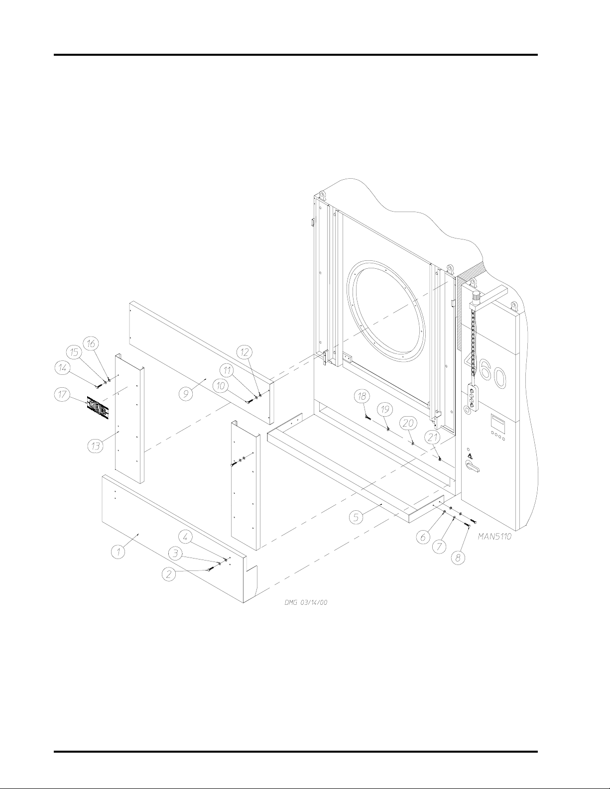
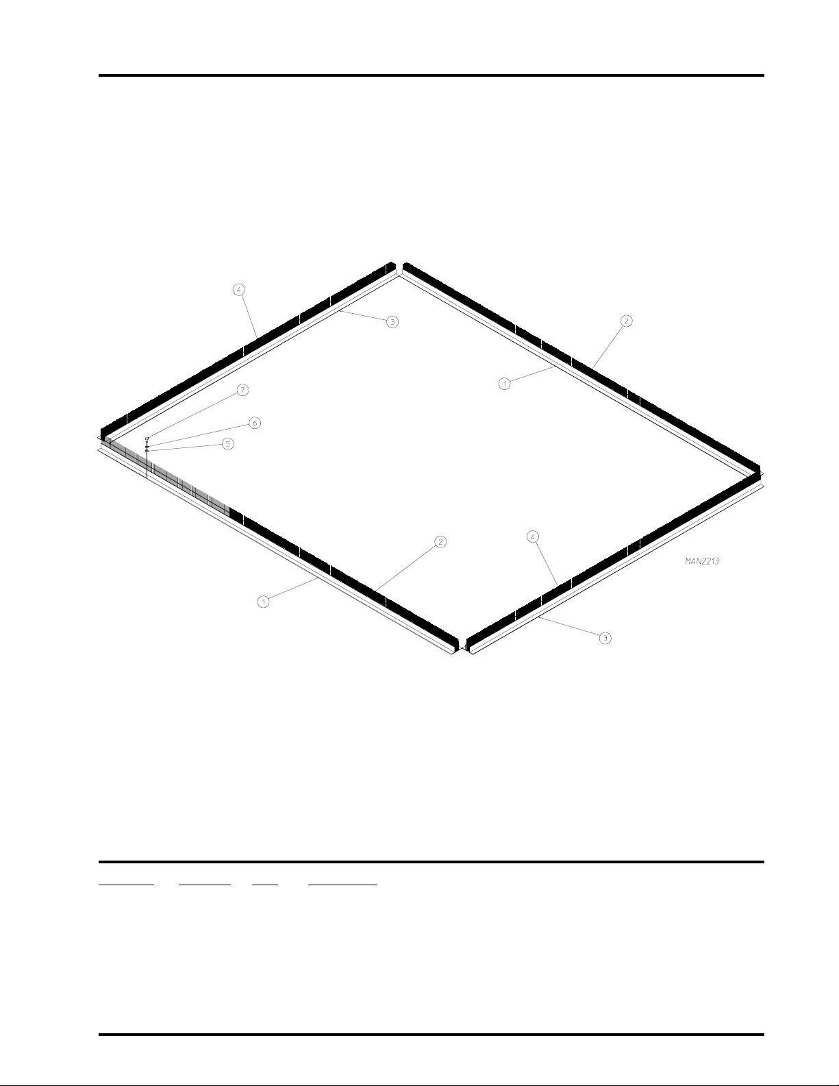
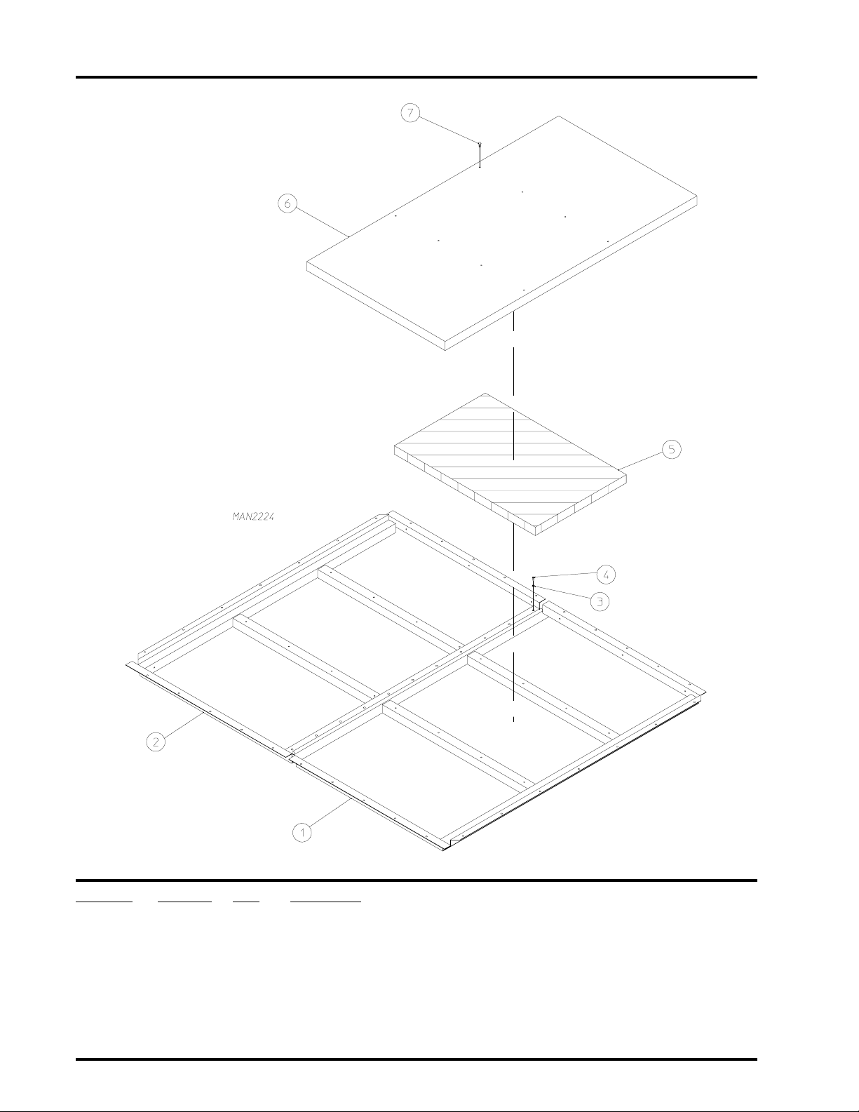
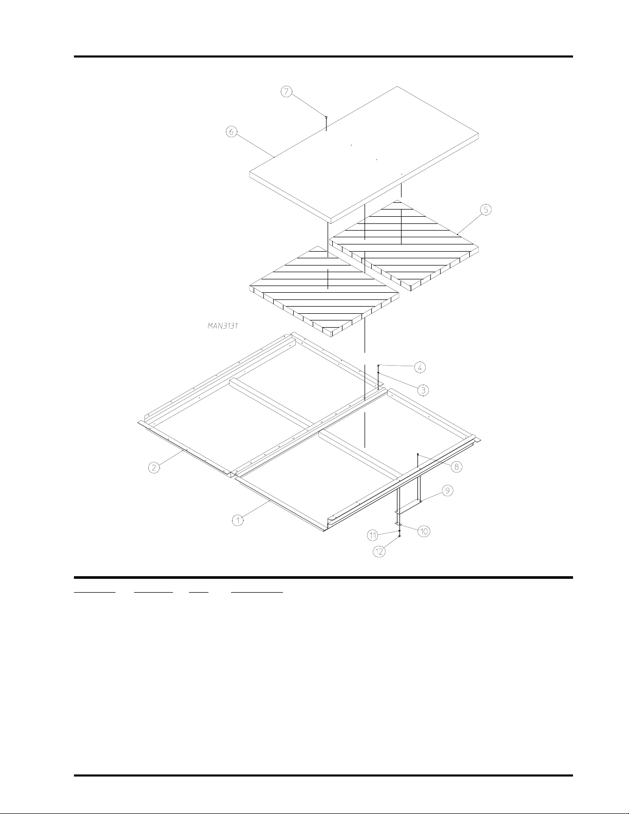
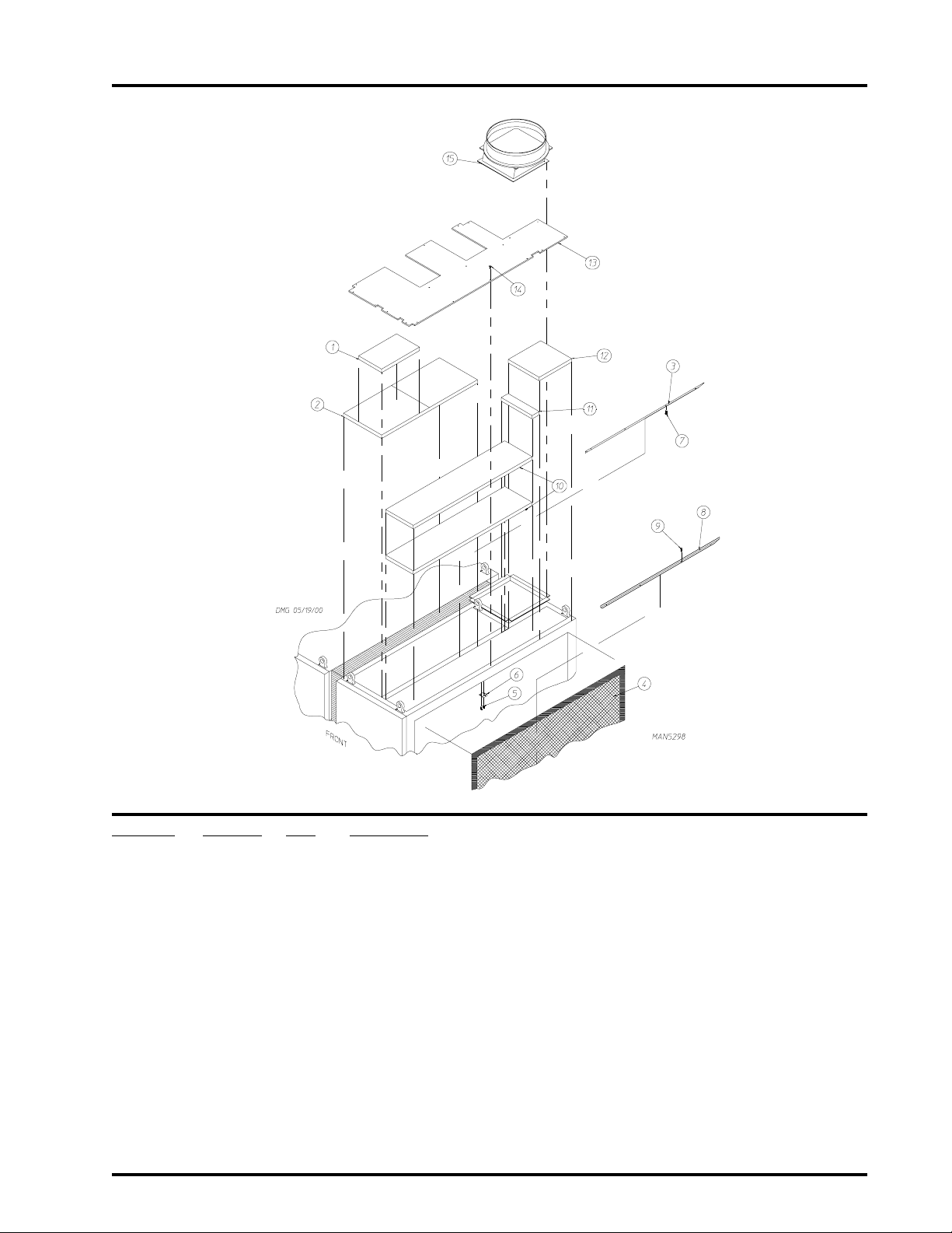
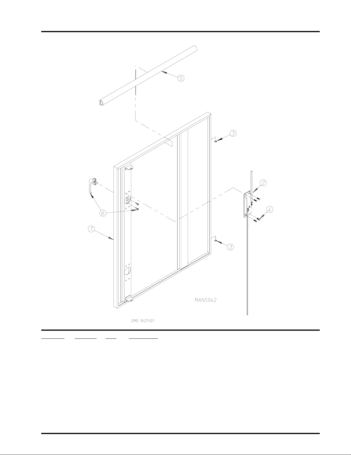
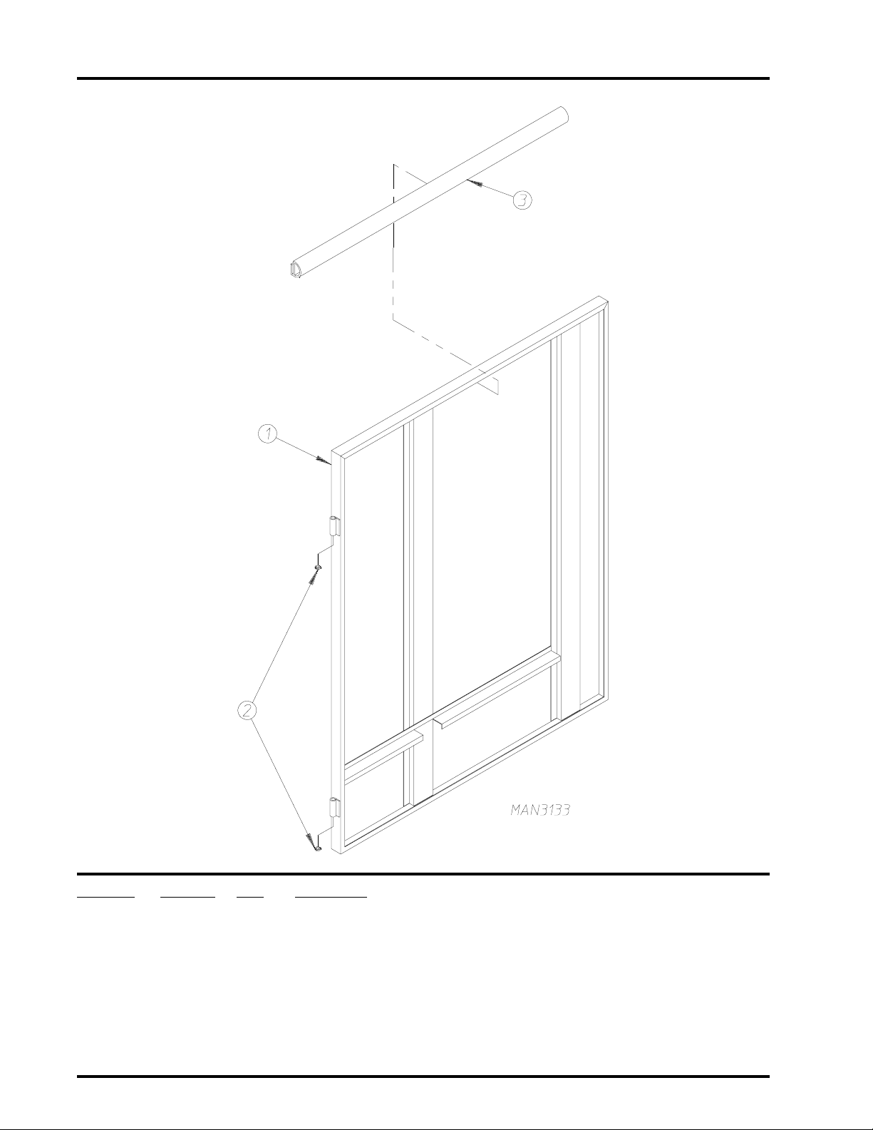
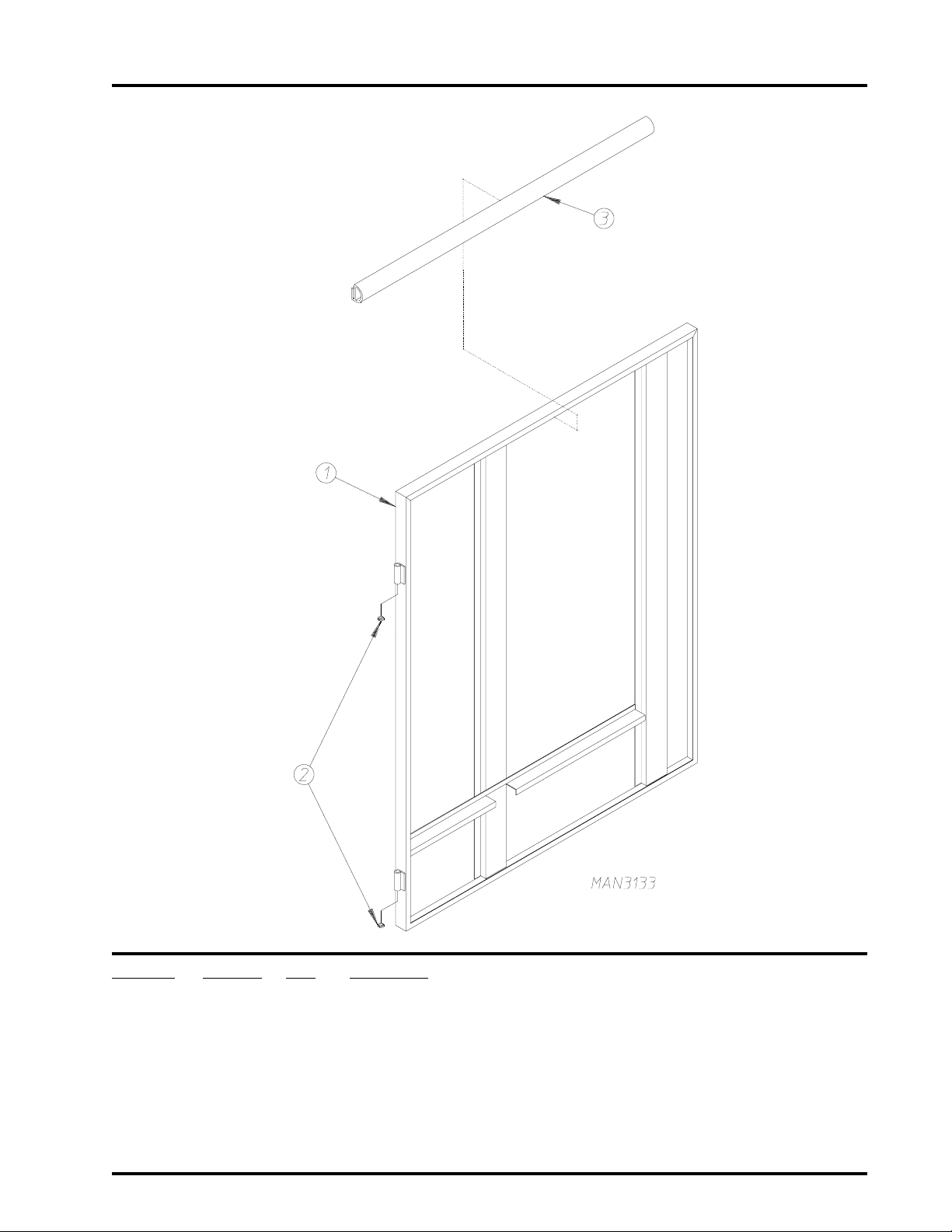
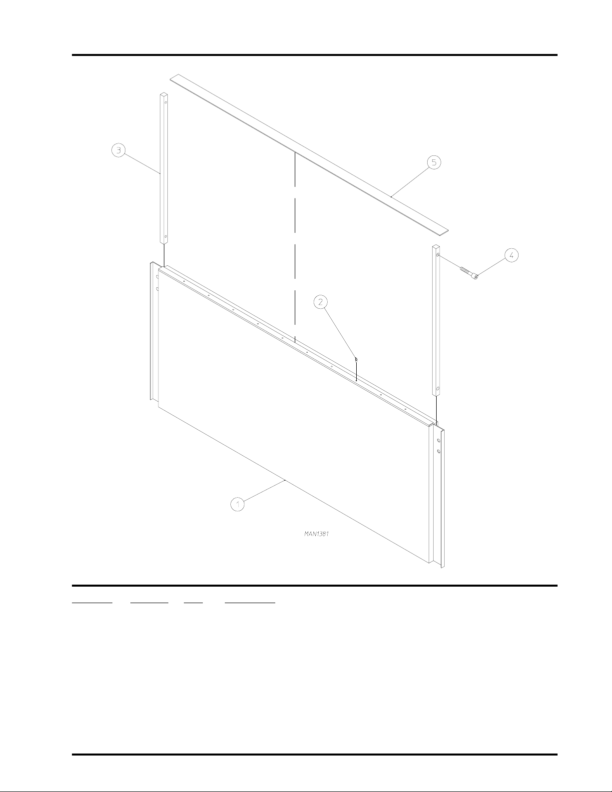
Front Safety Panel Assemblies
Illus. No. Part No. Qty. Description
1* 820897 1 Rigid Bottom Safety Panel
2 150501 4 5/16-18 x 3/4” Tap Bolt
3 153002 4 5/16” Lock Washer
4 153001 4 5/16” Flat Washer
5 820636 1 Step Bar
6 153011 4 9/ 1 6” I .D . x 1 - 3/ 8 ” O . D. F la t Wash er
7 153026 4 1/2” Lock Washer
8 150605 4 1/2-13 x 1-1/2” Tap Bolt
9* 820594 1 Top Panel
10 150514 4 5/16-18 x 2-1/4” Tap Bolt
11 153002 4 5/16” Lock Washer
12 153001 4 5/16” Flat Washer
13* 332018 2 Loading Door Side Panel
14 150501 16 5/16-18 x 3/4” Tap Bolt
15 153002 16 5/16” Lock Washer
16 153001 16 5/16” Flat Washer
17 112368 1 Milnor Logo
870011 1 Double Tape Kit ONLY
18 150600 7 3/8-16 x 1-1/2” Tap Bolt
19 153005 7 3/8” Lock Washer
20 153004 7 3/8” Flat Washer
21 154340 7 7/16” Beveled Washer
5
* Specify color when ordering.
T elephone: (508) 678-9000 Fax: (508) 678-9447
Page 8
6
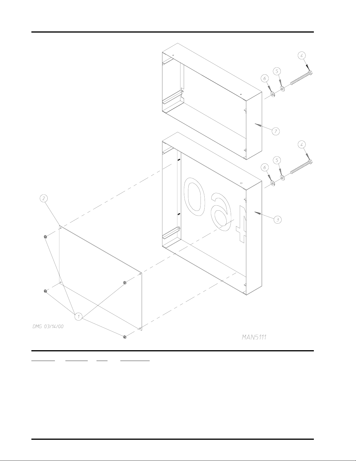
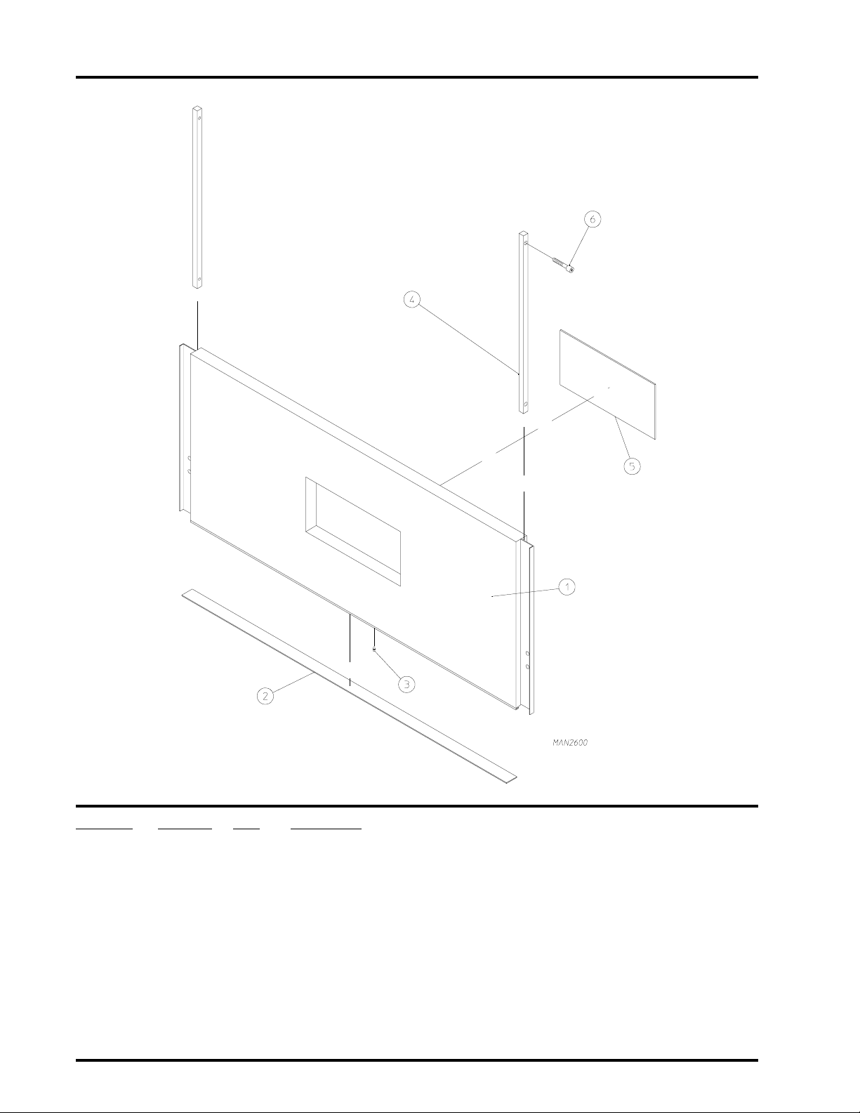
Character Panel Assembly
Illus. No. Part No. Qty. Description
1 152014 4 1/4-20 Free Spin Wash Nut
2 331959 1 Character Panel Backing Plate
3* 846868 1 Character Panel
4 150515 8 5/16-18 x 7-1/2” Hex Head Bolt
5 153002 8 5/16” Lock Washer
6 153001 8 5/16” Flat Washer
7* 846793 1 Heat Console Top Front Safety Panel
* Specify color when ordering.
American Dryer Corporation 88 Currant Road / Fall River, MA 02720-4781
Page 9
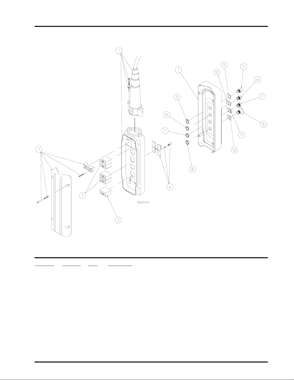
Pendant Assembly
7
Illus. No. Part No. Qty. Description
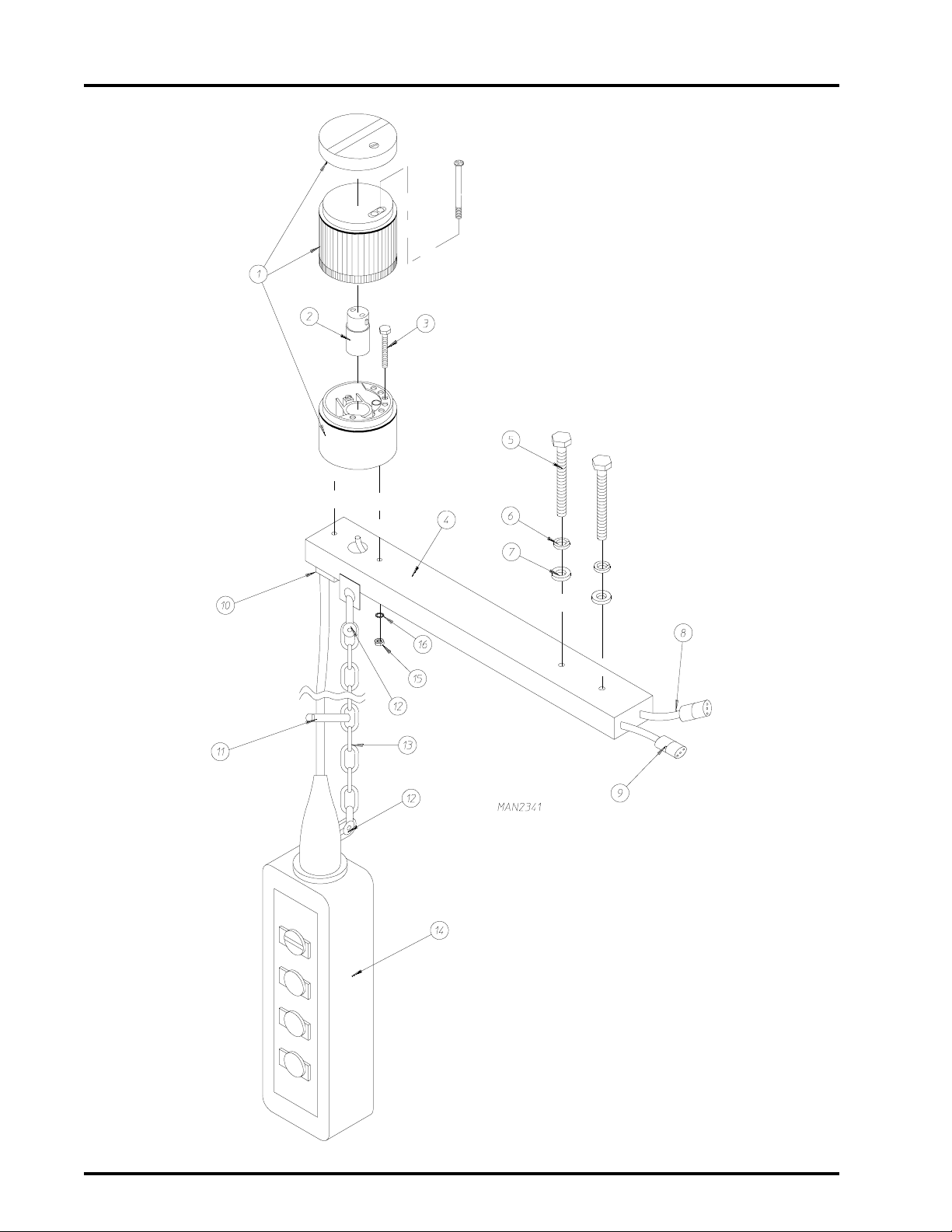
1 881302 1 Pendant Assembly Complete
(includes illus. nos. 1 through 12)
121149 1 4-Hole Pendant Enclosure
2 132386 4 Normally Open (N.O.) Contact Block
3 132387 1 Normally Closed (N.C.) Contact Block
4 132385 1 Mechanical Interlock
5 122350 1 3-Position Selector Switch
6 123205 1 “White” Booted Push-Button
7 123206 1 “Black” Booted Push-Button
8 122352 1 Small “EMERGENCY STOP” (E-STOP) Twist Lock Switch
9 122418 1 “LOAD LEVEL” Special Nameplate
10 122416 1 “REVERSE” Standard Nameplate
11 122415 1 “FORWARD” Standard Nameplate
12 122417 1 “EMERGENCY STOP” (E-STOP) Special Nameplate
T elephone: (508) 678-9000 Fax: (508) 678-9447
Page 10
8
Pendant Mounting Assembly
American Dryer Corporation 88 Currant Road / Fall River, MA 02720-4781
Page 11

Pendant Mounting Assembly
Illus. No. Part No. Qty. Description
1 123218 1 “Orange” Lens Unit
2 123219 1 110 VAC Replacement Lamp
3 150103 2 #8-32 x 3/4” Phillips Round Head Machine Screw
4 820545 1 Mounting Arm and Hand Control Assembly
5 150526 2 1/4-20 x 3” Hex Head Machine Bolt
6 153007 2 1/4” Lock Washer
7 153018 2 1/4” Flat Washer
8 847313 1 Annunciator Cable
9 847319 1 Pendant Cable
10 121400 1 7/8” Universal Bushing
11 121508 6 Black W ire-Tie
12 108126 2 Anchor Shackle with Pin
13 108125 1 6’ Chain
14 881302 1 Pendant Assembly Complete
(includes illus. nos. 1 through 14)
15 152001 2 #8-32 Hex Nut
16 153012 2 #8 Internal Star Washer
9
T elephone: (508) 678-9000 Fax: (508) 678-9447
Page 12
10
Control Door Assembly
American Dryer Corporation 88 Currant Road / Fall River, MA 02720-4781
Page 13

Control Door Assembly
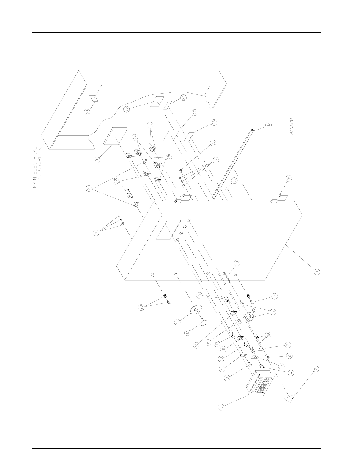
Illus. No. Part No. Qty. Description
1* 847336 1 Control Door Assembly Complete
(includes illus. nos. 1 through 29 and 32)
846785 1 Control Door Assembly
(includes illus. nos. 14, 20, 31, and 32)
2 114007 1 “DANGER - High Voltage” Label
3 137922 1 Input/Output (I/O) Interface Terminal - Empty
4 123215 1 “Blue” POWER ON Lens
5 122423 1 “POWER ON” Nameplate
6 123216 1 “Red” SPRINKLER ON Lens
7 122414 1 “SPRINKLER POWER ON” Label
8 123201 1 “Green” Lighted Operator
9 122410 1 “ON” Legend Plate
10 123204 1 “Red” Push-Button Operator
11 122421 1 “OFF” Engraved Nameplate
12 170211 1 Main Door Interlock Handle
13 170213 1 Main Shaft Extension
14 160050 1 Door Lock ONLY Less Key (keyed to number XX4451)
15 123200 1 “Amber” Push-Button Lighted Operator
16 122420 1 “SPRINKLER STOP” Label
17 122351 1 “EMERGENCY STOP” (E-STOP) Twist Lock Switch
18 122419 1 “EMERGENCY STOP” (E-STOP) Label - Yellow
19 123211 2 Incandescent Bulb - 120 VAC
20 160050 1 Door Lock ONLY Less Key (keyed to number XX4451)
21 121505 2 Control Panel Ty-Wrap Mount
22 132395 2 Normally Closed (N.C.) Contact Block with Base
23 847335 2 Enclosure Door Lights and Control Cable
24 123209 2 Direct Supply Base - 120 VAC
25 112046 1 “IMPORTANT For Computer Ground” Label
26 112017 1 “ADC Name, Address, Phone No.” Label
27 122426 1 “MULTI-POWER SOURCE Caution” Label
28 112025 1 “CAUTION - Disconnect Supply” Label
29 121509 3 Ty-Wrap Metal Clip on Mount
30 112060 1 Model Number/Serial Number Label
31 153068 2 Brass Hinge Washer
32 102312 16 Gray Silicone Extruded Gasket (sold by the foot)
33 121493 7 Nylon Push-In Mount
11
* Specify color when ordering.
T elephone: (508) 678-9000 Fax: (508) 678-9447
Page 14
12
Front Load Door Panel Assembly
American Dryer Corporation 88 Currant Road / Fall River, MA 02720-4781
Page 15

Front Load Door Panel Assembly
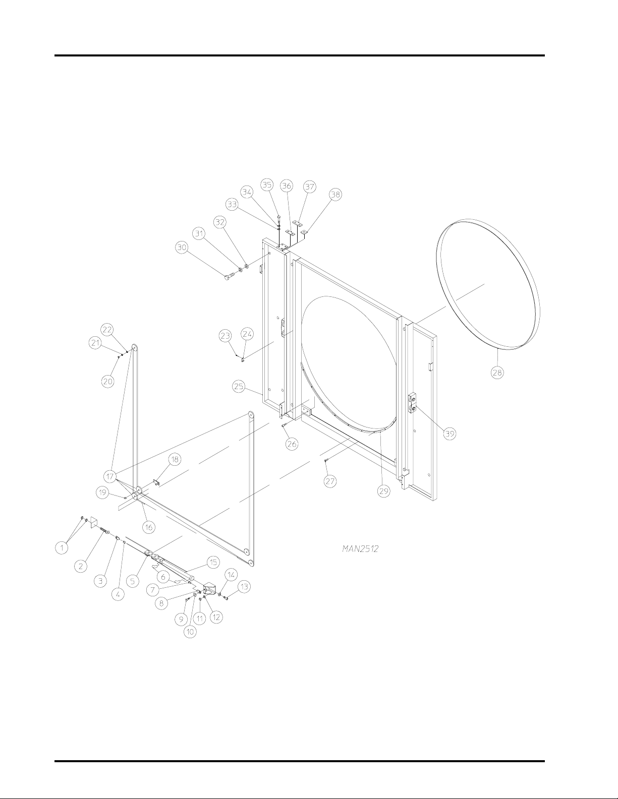
Illus. No. Part No. Qty. Description
1 152004 2 5/16-18 Hex Nut
2 170370 1 Turnbuckle
3 170373 1 Wire Rope Thimble
4 170371 1 Wire Rope Clamp
5 -------- 1 Cylinder Clevis
(refer to Cylinder Clevis Assembly on page 14)
6 143153 2 1/4” x 1/4” M.P.T. Elbow
7 170371 1 Wire Rope Clamp
8 170373 1 Wire Rope Thimble
9 150617 1 3/8-16 x 1” Hex Head Machine Bolt
10 153003 1 3/8” I.D. x 1-1/2” O.D. Fender Washer
11 152005 1 3/8-16 Hex Nut
12 153005 1 3/8” Lock Washer
13 150439 4 5/16-24 x 3/4” Socket Cap Screw
14 153002 4 5/16” Lock Washer
15 100554 1 2-1/2” Bore x 12-9/16” Door Piston
16 170372 1 Wire Rope (45’ length)
17 101 1 90 6 Cable Pulley
18 820510 2 Pulley Shaft Plate
19 331522 2 Bushing For Cable Pulley
20 152005 4 3/8-16 Hex Nut
21 153005 4 3/8” Lock Washer
22 331524 4 Plain Bearing For Cable Pulley
23 154200 2 5/32” Pop Rivet
24 331909 1 Load Door Tab
25* 820880 1 Front Panel ONLY
26 150441 2 1/4-20 x 1-3/8” Flat Head Socket Cap Screw
27 150412 9 #10-16 x 3/4” Phillips Round Head Crimptite Screw
28 116009 1 200” x 1-3/8” x 3/8” Basket (tumbler) Felt ONLY
881448 1 Basket (tumbler) Felt Replacement Kit
29 102385 1 Nylon Load Door Gasket
30 150617 8 3/8-16 x 1” Hex Head Machine Bolt
31 153005 8 3/8” Lock Washer
32 153004 8 3/8” Flat Washer
33 153011 4 9/ 1 6” I .D . x 1 - 3/ 8 ” O . D. F la t Wash er
34 153026 4 1/2” Lock Washer
35 150605 4 1/ 2-13 x 1-1/2” Tap Bolt
36 331789 4 Front Panel Hinge Top Shim
37 331786 2 Front Panel Hinge Top Spacer
38 820523 4 Bottom Hinge Spacer
39 820664 4 Basket (tumbler) Retaining Wheel Mount Assembly
13
* Specify color when ordering.
T elephone: (508) 678-9000 Fax: (508) 678-9447
Page 16
14
Cylinder Clevis Assembly
Illus. No. Part No. Qty. Description
1 154313 3 12 m m x 4 4 mm Hex Head Cap Screw
2 153011 2 9/16” I.D. x 1-3/8” O.D. Flat Washer
3 153026 3 1/2” Lock Washer
4 152040 3 12 m m Hex Nut
5 154304 1 1/4-20 x 3/8” Knurled Socket Setscrew
6 820630 1 Cylinder Clevis Assembly Complete
(includes illus. nos. 1 through 8)
820517 1 Cylinder Clevis ONLY
7 331524 4 Plain Bearing For Cable Pulley
8 1011 90 2 4” Cable Pulley
9 -------- 1 Wire Rope
(refer to Front Load Door Panel Assembly on page 12 and page 13)
American Dryer Corporation 88 Currant Road / Fall River, MA 02720-4781
Page 17
Console Brush Assembly
15
Illus. No. Part No. Qty. Description
1 170177 2 76-9/16” Brush Holder
2 170178 2 76-9/16” x 2-1/8” Wire Brush
3 170184 2 51-7/16” Brush Holder
4 170179 2 51-7/16” x 2-1/8” Wire Brush
5 153018 52 1/4” Flat Washer
6 153007 52 1/4” Lock Washer
7 150510 52 1/4-20 x 3/4” Hex Head Machine Bolt
T elephone: (508) 678-9000 Fax: (508) 678-9447
Page 18
16
T op Access Door Assembly
For Gas Models ONLY
Illus. No. Part No. Qty. Description
1 846769 1 Top Right Access Door Assembly
2 846771 1 Top Left Access Door Assembly
3 153007 11 1/4” Lock Washer
4 150512 11 1/4-20 x 1/2” Hex Head Machine Bolt
5 116765 6 Top Access Door Insulation
6 346516 2 Top Access Door Cover
7 150301 16 #8-18 x 7/16” Phillips Pan Head TEK Screw
American Dryer Corporation 88 Currant Road / Fall River, MA 02720-4781
Page 19
T op Access Door Assembly
For S team Models ONL Y
17
Illus. No. Part No. Qty. Description
1 846821 1 Top Right Panel Assembly
2 846771 1 Top Left Panel Assembly
3 153007 11 1/4” Lock Washer
4 150512 11 1/4-20 x 1/2” Hex Head Machine Bolt
5 116765 6 Top Access Door Insulation
6 346516 2 Top Access Door Cover
7 150301 8 #8-18 x 7/16” Phillips Pan Head TEK Screw
8 150103 4 #8-32 x 3/4” Phillips Round Head Machine Screw
9 117705 1 Sliding Pad
10 331998 1 Sliding Pad Strip
11 153012 4 #8 Internal Star Washer
12 152001 4 #8-32 Hex Nut
T elephone: (508) 678-9000 Fax: (508) 678-9447
Page 20
18
Top Console Panel Assembly
For Gas Models ONLY
Illus. No. Part No. Qty. Description
1 116764 2 Top Right Insulation
2 116763 2 Top Left Insulation
3 346464 1 Top Right Cover
4 346463 1 Top Left Cover
5 150522 18 1/4-20 x 1/2” Hex Head Washer TEK Screw
6 846796 1 Transition Piece
7 346612 1 Door Catch (for top console left hand door assembly)
8 150522 2 1/4-20 x 1/2” Hex Head Washer TEK Screw
American Dryer Corporation 88 Currant Road / Fall River, MA 02720-4781
Page 21
Top Console Panel Assembly
For S team Models ONL Y
19
Illus. No. Part No. Qty. Description
1 116771 1 19” x 48” Steam Coil T op Insulation
2 116770 2 11-1/2” x 19” Next T o Steam Coil Insulation
3 346587 1 Upper Angle Lint Screen Support
4 846813 1 Steam Coil Screen
5 150522 2 1/4-20 x 1/2” Hex Head Washer TEK Screw
6 346612 1 Door Catch
7 150522 4 1/4-20 x 1/2” Hex Head Washer TEK Screw
8 346586 1 Lower Angle Lint Screen Support
9 150522 4 1/4-20 x 1/2” Hex Head Washer TEK Screw
10 116767 2 13-3/4” x 59-1/2” Center Console Insulation
1 1 116769 1 3-1/2” x 15-1/2” Small Steam Box Insulation
12 116768 2 15-1/2” x 16-1/4” Steam Box Insulation
13 346665 1 Steam Console Top
14 150522 17 1/4-20 x 1/2” Hex Head Washer TEK Screw
15 846796 1 Transition Piece
T elephone: (508) 678-9000 Fax: (508) 678-9447
Page 22
20
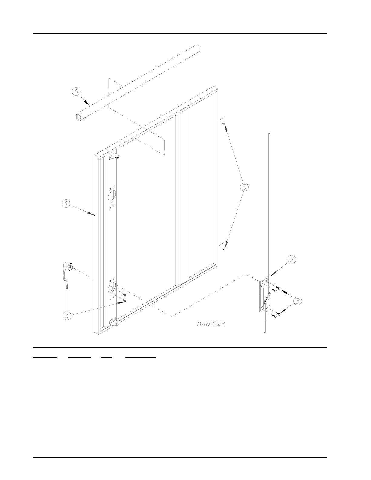
Top Console Left Hand Door Assembly
For Gas Models ONLY
Illus. No. Part No. Qty. Description
1* 846783 1 Top Console Left Door Assembly Complete
(includes illus. nos. 1 through 6)
881363 1 Top Console Left Door Assembly with Gasket ONLY
(includes illus. nos. 1 and 6)
2 160205 1 2-Point Dead Bolt Latch
3 150512 4 1/4-20 x 1/2” Hex Head Machine Bolt
4 170217 1 Door Handle
5 153068 2 Brass Hinge Washer
6 102312 10 Gray Silicone Extruded Gasket (sold by the foot)
* Specify color when ordering.
American Dryer Corporation 88 Currant Road / Fall River, MA 02720-4781
Page 23
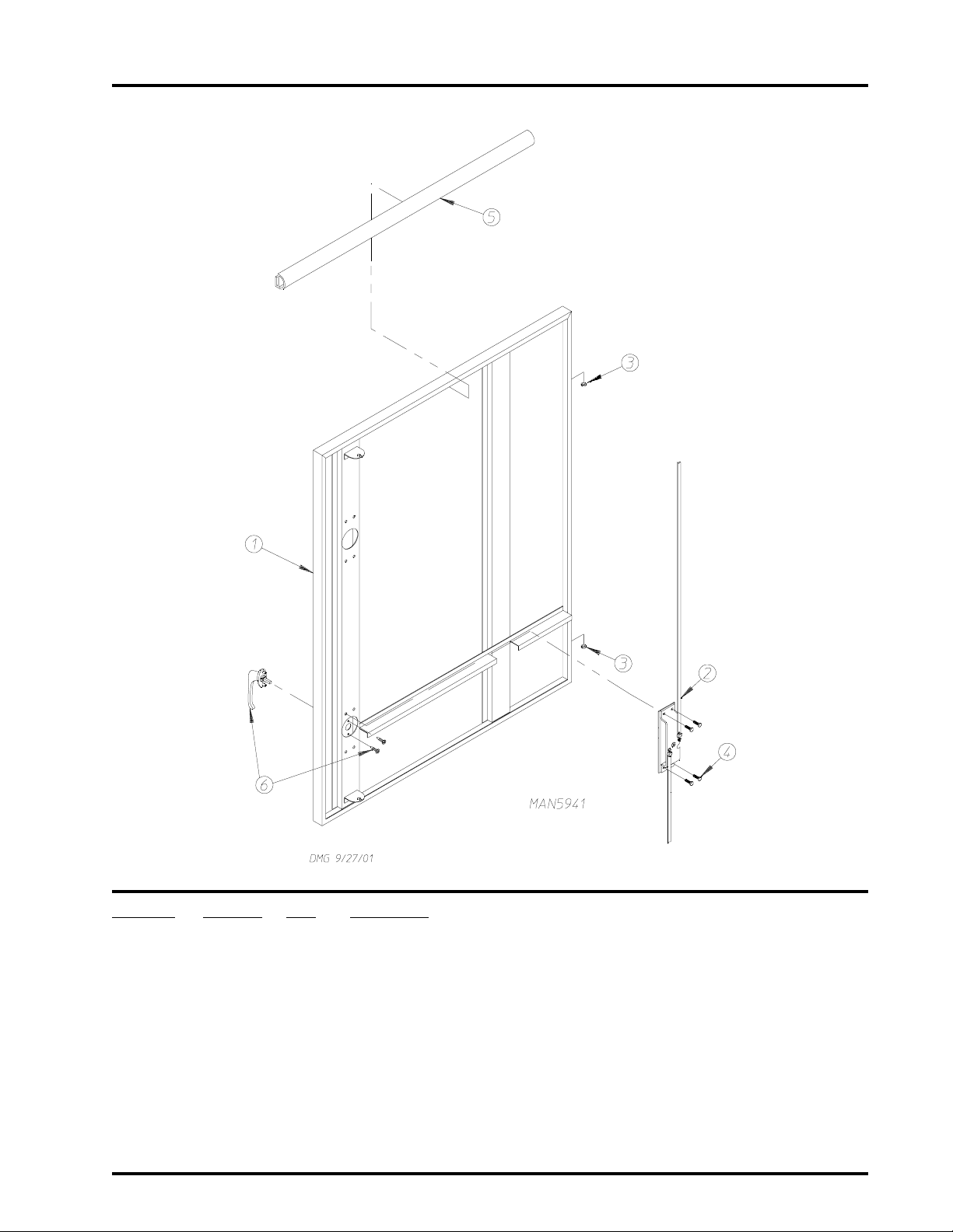
Top Console Left Hand Door Assembly
For S team Models ONL Y
21
Illus. No. Part No. Qty. Description
1* 846828 1 Top Console Left Door Assembly Complete
(includes illus. nos. 1 through 6)
881489 1 Top Console Left Door Assembly with Gasket ONLY
(includes illus. nos. 1 and 6)
2 160205 1 2-Point Dead Bolt Latch
3 153068 2 Brass Hinge Washer
4 150512 4 1/4-20 x 1/2” Hex Head Machine Bolt
5 102312 10 Gray Silicone Extruded Gasket (sold by the foot)
6 170217 1 Door Handle
* Specify color when ordering.
T elephone: (508) 678-9000 Fax: (508) 678-9447
Page 24
22
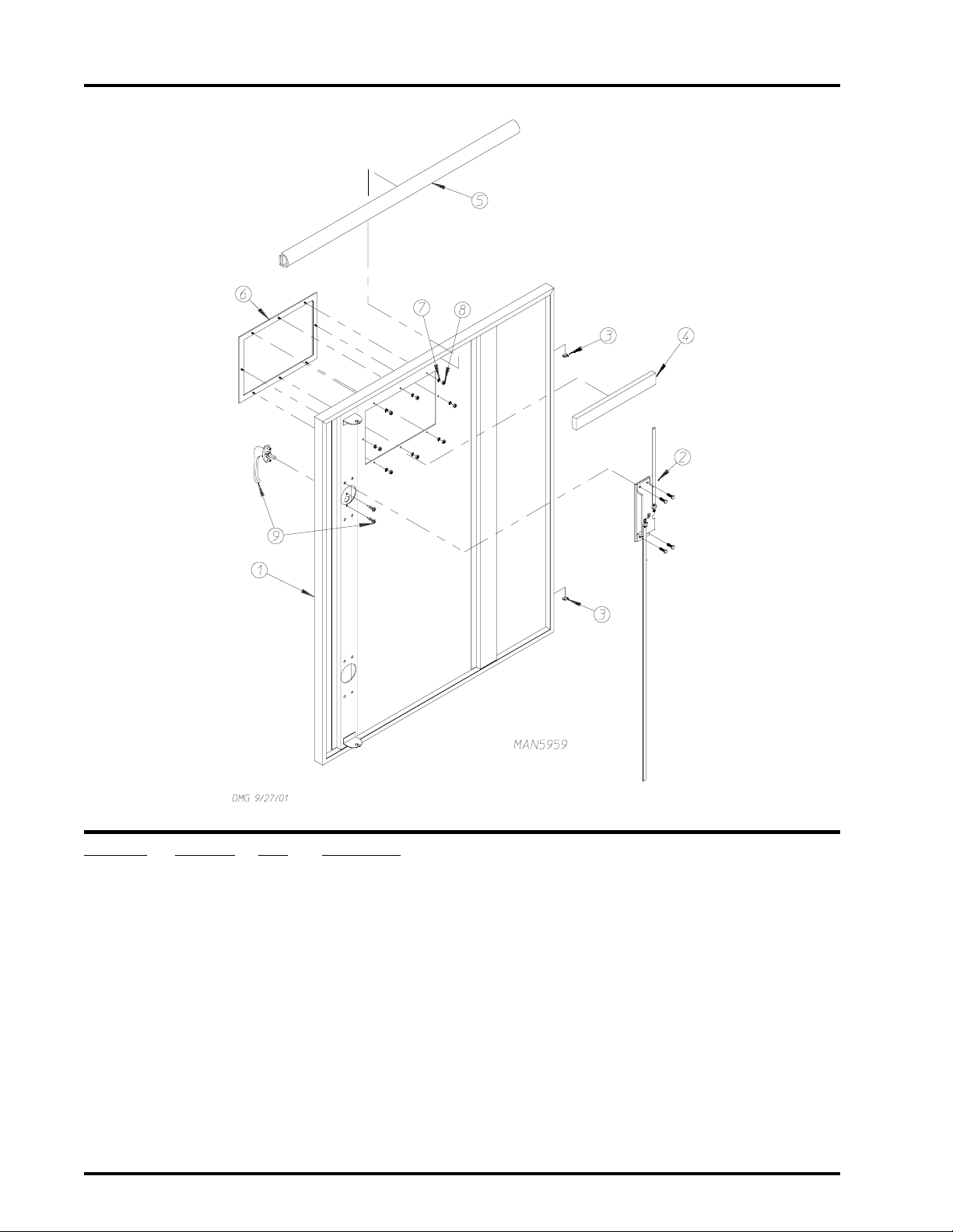
Lower Console Left Hand Door Assembly
For Gas Models ONLY
Illus. No. Part No. Qty. Description
1* 846779 1 Lower Console Left Door Assembly Complete
(includes illus. nos. 1 through 9)
881365 1 Lower Console Left Door Assembly with Gasket ONLY
(includes illus. nos. 1 and 5)
2 160205 1 2-Point Dead Bolt Latch
3 153068 2 Brass Hinge Washer
4 102350 1 68-1/2” Gasket
5 102312 10 Gray Silicone Extruded Gasket (sold by the foot)
6 180307 2 Horizontal Trim (sold by the foot)
7 180308 2 Vertical T rim (sold by the foot)
8 150201 12 #10-32 x 1/4” Slotted Pan Head TEK Screw
9 170217 1 Door Handle
* Specify color when ordering.
American Dryer Corporation 88 Currant Road / Fall River, MA 02720-4781
Page 25
Lower Console Left Hand Door Assembly
For S team Models ONL Y
23
Illus. No. Part No. Qty. Description
1* 846824 1 Lower Console Left Door Assembly Complete
(includes illus. nos. 1 through 7)
881490 1 Lower Console Left Door Assembly with Gasket ONLY
(includes illus. nos. 1 and 5)
2 160205 1 2-Point Dead Bolt Latch
3 153068 2 Brass Hinge Washer
4 150512 4 1/4-20 x 1/2” Hex Head Machine Bolt
5 102312 11 Gray Silicone Extruded Gasket (sold by the foot)
6 170217 1 Door Handle
* Specify color when ordering.
T elephone: (508) 678-9000 Fax: (508) 678-9447
Page 26
24
Heat Console Right Hand Door Assembly
For S team Models ONL Y
Illus. No. Part No. Qty. Description
1* 846830 1 Heat Console Right Door Assembly Complete
(includes illus. nos. 1 through 3)
881488 1 Heat Console Right Door Assembly with Gasket ONLY
(includes illus. nos. 1 and 3)
2 153068 2 Brass Hinge Washer
3 102312 10 Gray Silicone Extruded Gasket (sold by the foot)
* Specify color when ordering.
American Dryer Corporation 88 Currant Road / Fall River, MA 02720-4781
Page 27
Heat Console Right Hand Door Assembly
For Gas Models ONLY
25
Illus. No. Part No. Qty. Description
1* 846781 1 Heat Console Right Door Assembly
(includes illus. nos. 1 through 3)
881364 1 Heat Console Right Door Assembly with Gasket ONLY
(includes illus. nos. 1 and 3)
2 153068 2 Brass Hinge Washer
3 102312 10 Gray Silicone Extruded Gasket (sold by the foot)
* Specify color when ordering.
T elephone: (508) 678-9000 Fax: (508) 678-9447
Page 28
26
Top Load Door Assembly
Illus. No. Part No. Qty. Description
1* 820882 1 Top Load Door Assembly Complete
(includes illus. nos. 1 through 6)
820881 1 Top Load Door ONLY
2 116008 1 Load Door Felt (55” length)
- 170730 1 Glass/Gasket (felt) Silicone Adhesive (10.3 oz. cartridge)...Not Illustrated
3 154200 10 5/32” Pop Rivet
4 331594 2 Brass Door Runner
5 102215 1 Door Window
6 150440 4 5/16-18 x 1” Socket Cap Screw
* Specify color when ordering.
American Dryer Corporation 88 Currant Road / Fall River, MA 02720-4781
Page 29
Bottom Load Door Assembly
27
Illus. No. Part No. Qty. Description
1* 820884 1 Bottom Load Door Assembly Complete
(includes illus. nos. 1 through 5)
820883 1 Bottom Load Door ONLY
2 154200 10 5/32” Pop Rivet
3 331594 2 Brass Door Runner
4 150440 4 5/16-18 x 1” Socket Cap Screw
5 116008 1 Load Door Felt (55” length)
- 170730 1 Gasket (felt) Silicone Adhesive (10.3 oz. cartridge)...Not Illustrated
* Specify color when ordering.
T elephone: (508) 678-9000 Fax: (508) 678-9447
Page 30
28
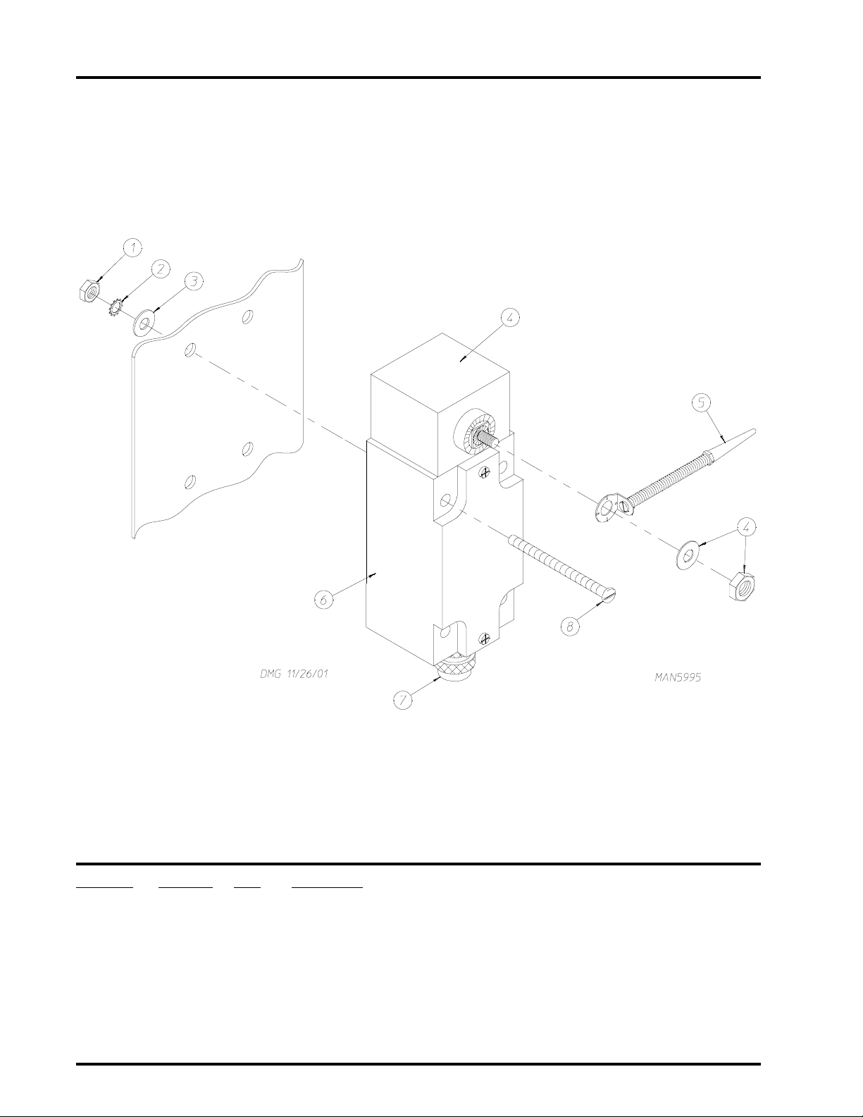
Load Door Closed Switch Assembly
Illus. No. Part No. Qty. Description
1 152001 4 #8-32 Hex Nut
2 153012 4 #8 Internal Star Washer
3 153000 4 #8 Steel Burr
4 122365 1 Rotational Head
5 122368 1 Coil Spring Lever Arm
6 122367 1 Limit Switch Body
7 120655 1 Blue Cord Grip Connector
8 150109 4 #8-32 x 2” Phillips Round Head Machine Screw
American Dryer Corporation 88 Currant Road / Fall River, MA 02720-4781
Page 31

Inlet Air Adapter Assembly
29
Illus. No. Part No. Qty. Description
1 846838 1 Inlet Air Adapter Assembly
2 346612 1 Door Catch
3 150522 3 1/4-20 x 1/2” Hex Head Washer TEK Screw
- 346631 1 Base Side Cover...Not Illustrated
T elephone: (508) 678-9000 Fax: (508) 678-9447
Page 32

30
Inlet Air Adapter Left Door Assembly
Illus. No. Part No. Qty. Description
1 846837 1 Left D oor Assembly
2 170217 1 Door Handle
3 102315 23 Silicone Rubber Extruded Gasket (sold by the foot)
- 170730 1 Gasket (felt) Silicone Adhesive (10.3 oz. cartridge)...Not Illustrated
4 160205 1 2-Point Dead Bolt Latch
5 153068 2 Brass Hinge Washer
6 150512 4 1/4-20 x 1/2” Hex Head Machine Bolt
American Dryer Corporation 88 Currant Road / Fall River, MA 02720-4781
Page 33

Inlet Air Adapter Right Door Assembly
31
Illus. No. Part No. Qty. Description
1 846841 1 Right Door Assembly
2 153068 2 Brass Hinge Washer
3 102315 3 Silicone Rubber Extruded Gasket (sold by the foot)
- 170730 1 Gasket (felt) Silicone Adhesive (10.3 oz. cartridge)...Not Illustrated
T elephone: (508) 678-9000 Fax: (508) 678-9447
Page 34

32
Left Side Panel Assembly
American Dryer Corporation 88 Currant Road / Fall River, MA 02720-4781
Page 35

Left Side Panel Assembly
Illus. No. Part No. Qty. Description
1* 346522 1 Lower Left Side Safety Panel
2 150514 4 5/16-18 x 2-1/4” Tap Bolt
3 153001 4 5/16” Flat Washer
4 153002 4 5/16” Lock Washer
5* 846847 1 Middle Left Side Safety Panel
6 150514 2 5/16-18 x 2-1/4” Tap Bolt
7 153001 2 5/16” Flat Washer
8 153002 2 5/16” Lock Washer
9* 846848 1 Upper Left Side Safety Panel
10 150514 4 5/16-18 x 2-1/4” Tap Bolt
11 153001 4 5/16” Flat Washer
12 153002 4 5/16” Lock Washer
13* 346521 1 Basket (tumbler) Base Tilt Safety Panel
14 150501 6 5/16-18 x 3/4” Tap Bolt
15 153001 6 5/16” Flat Washer
16 153002 6 5/16” Lock Washer
33
* Specify color when ordering.
T elephone: (508) 678-9000 Fax: (508) 678-9447
Page 36

34
Lint Chamber Air Switch Assembly
Illus. No. Part No. Qty. Description
1 136993 1 Air Differential Switch with Dust Proof Cap
2 150501 1 5/16-18 x 3/4” Tap Bolt
3 153002 1 5/16” Lock Washer
4 882157 1 1/4” Aluminum Tubing (sold by the foot)
5 143152 1 1/4” x 1/8” M.P.T. Straight Connector
6 331470 1 Lint Air Switch Bracket
7 150510 2 1/4-20 x 3/4” Hex Head Machine Bolt
8 153007 2 1/4” Lock Washer
American Dryer Corporation 88 Currant Road / Fall River, MA 02720-4781
Page 37

Right Hand Lint Drawer/Basket Door Assembly
35
NOTE: Duplicate ALL components for Left Hand Lint Drawer/Basket Door Assembly...Not Illustrated.
Illus. No. Part No. Qty. Description
1* 846795 1 Right Hand Lint Drawer/Basket Door Assembly Complete
(includes illus. nos. 1 through 5)
2 153068 2 Brass Hinge Washer
3 170217 1 Large Dryer Door Handle
4 160009 1 Adjustable Cam
5 102312 8 Gray Silicone Extruded Gasket (sold by the foot)
* Specify color when ordering.
T elephone: (508) 678-9000 Fax: (508) 678-9447
Page 38

36
Left Lint Drawer/Basket Assembly
Illus. No. Part No. Qty. Description
1* 846758 1 Left Stainless Steel Lint Basket Assembly
(for models mfd. as of August 7, 2000)
* 881265 1 Left Lint Drawer/Basket Assembly Complete
(includes illus. nos. 1 through 4)
2 331421 1 Lint Drawer/Basket Magnet Holder
3 154200 3 5/32” Pop Rivet
4 102109 1 7/8” x 1/2” x 1/2” Magnet
5 108217 1 Lint Basket/Drawer Screen Assembly
(for models mfd. prior to August 7, 2000)
6 150108 5 #8-32 x 1/2” Phillips Pan Head Machine Screw
7 346492 1 Base Lint Drawer/Basket Felt Strip
8 115989 1 Base Lint Basket Felt
9 153012 5 #8 Internal Star Washer
10 152001 5 #8-32 Hex Nut
1 1 346650 1 Lint Drawer/Basket Felt Stiffener
* Specify color when ordering.
American Dryer Corporation 88 Currant Road / Fall River, MA 02720-4781
Page 39

Right Lint Drawer/Basket Assembly
37
Illus. No. Part No. Qty. Description
1* 846758 1 Right Stainless Steel Lint Basket Assembly
(for models mfd. as of August 7, 2000)
* 881264 1 Right Lint Drawer/Basket Assembly Complete
(includes illus. nos. 1 through 4)
2 331421 1 Lint Drawer/Basket Magnet Holder
3 154200 3 5/32” Pop Rivet
4 102109 1 7/8” x 1/2” x 1/2” Magnet
5 108217 1 Lint Basket/Drawer Screen Assembly
(for models mfd. prior to August 7, 2000)
6 150108 5 #8-32 x 1/2” Phillips Pan Head Machine Screw
7 346492 1 Base Lint Drawer/Basket Felt Strip
8 115989 1 Base Lint Basket Felt
9 153012 5 #8 Internal Star Washer
10 152001 5 #8-32 Hex Nut
11 346650 1 Lint Drawer/Basket Felt Stiffener
* Specify color when ordering.
T elephone: (508) 678-9000 Fax: (508) 678-9447
Page 40

38
Solid Back Panel Assembly
American Dryer Corporation 88 Currant Road / Fall River, MA 02720-4781
Page 41

Solid Back Panel Assembly
Illus. No. Part No. Qty. Description
1 152005 16 3/8-16 Hex Nut
2 153005 16 3/8” Lock Washer
3 153004 16 3/8” Flat Washer
4 150508 16 3/8-16 x 3/4” Hex Head Machine Bolt
5 116009 1 200” x 1-3/8” x 3/8” Basket (tumbler) Felt
6* 331829 4 Solid Back Panel Cover
7 150621 16 5/16-18 x 1-1/2” Tap Bolt
8 153001 20 5/16” Flat Washer
9 153002 20 5/16” Lock Washer
10 150501 4 5/16-18 x 3/4” Tap Bolt
11 * 820855 1 Solid Back Panel Lower Guard
12 820664 4 Basket (tumbler) Retaining Wheel Mount Assembly
13 150615 6 1/4-20 x 3/4” Tap Bolt
14 153018 6 1/4” Flat Washer
15 153007 6 1/4” Lock Washer
16 152002 6 1/4-20 Hex Nut
17 820523 4 Bottom Hinge Spacer
18 331786 2 Top Spacer Front Panel Hinge
19 153011 4 9/ 1 6” I .D . x 1 - 3/ 8 ” O . D. F la t Wash er
20 153026 4 1/2” Lock Washer
21 150605 4 1/2-13 x 1-1/2” Tap Bolt
22 153002 4 5/16” Lock Washer
23 153001 4 5/16” Flat Washer
24 150501 4 5/16-18 x 3/4” Tap Bolt
25 820856 2 Lower Guard Mounting Channel
26 820603 1 Solid Back Panel
27 846846 2 Exhaust Insulation Panel
28 150225 12 5/16-18 x 3-1/2” Hex Head Machine Screw
29 153002 12 5/16” Lock Washer
30 153001 12 5/16” Flat Washer
31 846716 1 Basket (tumbler) ONLY
846802 1 Basket (tumbler) with Perforated Ribs (option)
(for fabric conditioning option Only)
847603 1 Basket (tumbler) with Removable Panels/Perforated (option)
32 346682 5 Removable Basket (tumbler) Panel/Perforated
33 150124 80 1/4-20 x 1/2” Stainless Steel Phillips Pan Head Screw
39
* Specify color when ordering.
T elephone: (508) 678-9000 Fax: (508) 678-9447
Page 42

40
Front/Rear Tilting Switch
Illus. No. Part No. Qty. Description
1 152001 4 #8-32 Hex Nut
2 153012 4 #8 Internal Star Washer
3 153000 4 #8 Steel Burr
4 331911 1 Tilt Switch Bracket
5 120655 1 Blue Cord Grip Connector
6 122367 1 Limit Switch Body
7 122365 1 Limit Switch ONLY
8 150109 4 #8-32 x 2” Phillips Round Head Machine Screw
9 122369 1 Roller Lever Arm
American Dryer Corporation 88 Currant Road / Fall River, MA 02720-4781
Page 43

T ilting Piston Assembly
41
Illus. No. Part No. Qty. Description
1 100563 1 6” Bore x 19” Stroke Cylinder with Clevis Pin
100433 1 6” Bore x 15” Stroke Cylinder with Clevis Pin (optional)
100488 1 Clevis Pin ONLY
2 143221 1 3/8” Brass Union Tee
3 143120 10 3/8” O.D. Poly-Flo T ubing (sold by the foot)
4 143298 2 3/8” x 90° Compression Elbow
5 143299 2 3/8” Tube Insert
6 100442 1 Rod Eye
7 154333 2 1/4-20 x 1” Cup Point Setscrew
8 102383 2 Cylinder Pin Bumper
9 150435 4 3/8-16 x 3” Socket Cap Screw
10 346491 1 1-3/8” Clevis Pin
11 100484 1 Rod Clevis
12 153034 1 1-1/4” Flat Washer
13 153036 1 1-1/4” Lock Washer
14 150516 1 1-1/4-12 x 2” Hex Head Bolt
T elephone: (508) 678-9000 Fax: (508) 678-9447
Page 44

42
Piston Post Assembly
For 1-W ay Tilt Models ONL Y
Illus. No. Part No. Qty. Description
1 846763 1 Piston Bar
2 100448 1 1” Pivot Pin
3 100442 1 Rod Eye
4 154333 2 1/4-20 x 1” Setscrew
5 150435 4 3/8-16 x 3” Socket Cap Screw
6 102383 2 Cylinder Pin Bumper
7 346491 1 1-3/8” Clevis Pin
8 100484 1 Rod Clevis
9 153034 1 1-1/4” Flat Washer
10 153036 1 1-1/4” Lock Washer
1 1 150516 1 1-1/4-12 x 2” Hex Head Bolt
American Dryer Corporation 88 Currant Road / Fall River, MA 02720-4781
Page 45

Filter/Regulator/Gauge (F/R/G) Assembly
43
Illus. No. Part No. Qty. Description
1 100478 1 1/2” N.P.T. Filter/Regulator/Gauge (F/R/G) Assembly
2 143120 * 3/8” O.D. Poly-Flo Tubing (sold by the foot)
3 143155 1 3/8” Street Elbow
4 143162 1 1/2” to 3/8” Reducing Bushing
5 332640 1 Filter/Regulator Mounting Bracket
6 143162 1 1/2” to 3/8” Reducing Bushing
7 143155 1 3/8” Street Elbow
8 143120 * 3/8” O.D. Poly-Flo Tubing (sold by the foot)
9 143155 1 3/8” Street Elbow
10 143257 1 3/8” F.P.T. Brass Bulkhead Adaptor
* As required.
T elephone: (508) 678-9000 Fax: (508) 678-9447
Page 46

44
Basket (T umbler) Drive Shaft Assembly
American Dryer Corporation 88 Currant Road / Fall River, MA 02720-4781
Page 47

Basket (T umbler) Drive Shaft Assembly
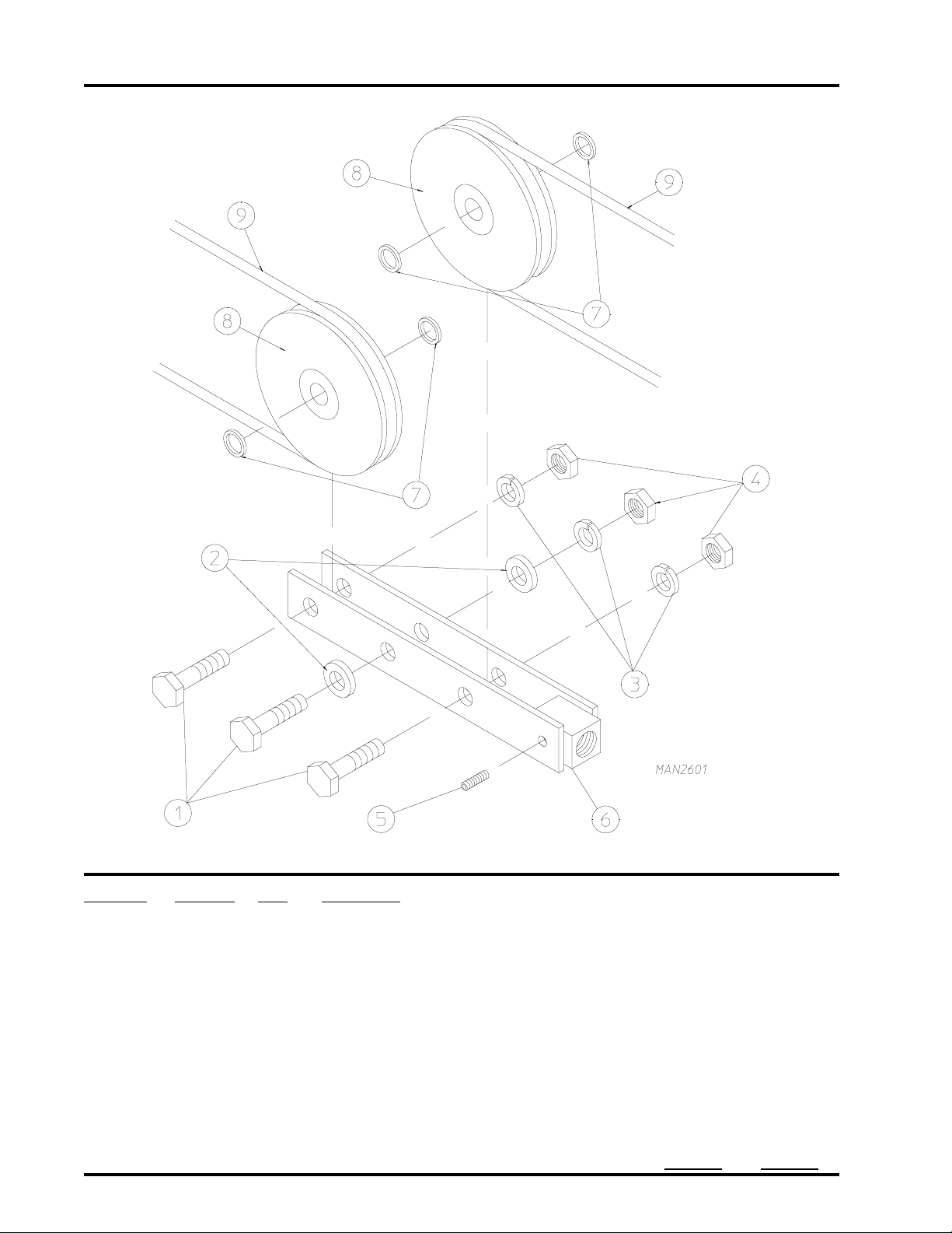
Illus. No. Part No. Qty. Description
1 820600 2 Drive Wheel Assembly with Hub
2 100712 2 1/2” x 1/2” x 3” Key
3 331760 2 Bearing Mount
4 880882 2 2” Pillow Block Bearing with Setscrews and Grease Fitting
5 153016 4 5/8” Flat Washer
6 150627 4 5/8-11 x 5” Hex Head Bolt
7 153016 2 5/8” Flat Washer
8 153015 4 5/8” Lock Washer
9 152010 4 5/8-11 Hex Nut
10 101022 1 2” Bore Tapered Bushing
11 101019 1 Taper Bushed Speed Reducer
12 154395 1 Gear Reducer Turnbuckle
13 150508 2 3/8-16 x 3/4” Hex Head Machine Bolt
14 153005 2 3/8” Lock Washer
15 153004 2 3/8” Flat Washer
16 10 1176 1 2B x 5.6 Pulley
17* 100118 2 5L-310 V-Belt
(for models mfd. as of August 14, 2000)
For 60 Hz Models ONLY
100143 2 A29 V-Belt (basket [tumbler] to drive motor)
For 60 Hz Models ONLY
(for models mfd. prior to August 14, 2000)
100119 2 5L-320 V-Belt
For 50 Hz Models ONLY
(for models mfd. as of August 14, 2000)
100138 2 A30 V-Belt (basket [tumbler] to drive motor)
For 50 Hz Models ONLY
(for models mfd. prior to August 14, 2000)
18 100709 1 3/8” x 3/8” x 2” Key
19 101196 1 SDS x 1-5/8” Bushing with Setscrew
20 346510 1 2” x 79-1/16” Drive Shaft
21 332838 2 Basket (tumbler) Bearing Spacer
22 150629 2 1/2-13 x 3-1/2” Hex Head Bolt
23 153026 2 1/2” Lock Washer
24 152011 2 1/2-13 Hex Nut
25 101191 2 2” Bore Tapered Bushing
26 101171 2 Lock Collar - 2” Bore
27 101025 1 Fulcrum
45
* Replace in matched sets (both belts).
T elephone: (508) 678-9000 Fax: (508) 678-9447
Page 48

46
Basket (T umbler) Retaining Wheel Mount Assembly
Illus. No. Part No. Qty. Description
1 152005 2 3/8-16 Hex Nut
2 153005 2 3/8” Lock Washer
3 820566 2 Retaining Wheel Assembly
4 153062 4 5/16” x 7/8” x 1/4” Spherical Washer
5 153004 2 3/8” Flat Washer
6 150438 2 3/8-16 x 3-1/4” Hex Head Machine Bolt
American Dryer Corporation 88 Currant Road / Fall River, MA 02720-4781
Page 49

Drive Motor Assembly
47
Illus. No. Part No. Qty. Description
1 100704 1 1/4” x 1/4” x 1-3/4” Key
2 1 0 114 4 1 SH x 1-1/8” Bushing
3 1 01187 1 2B x 3.6 Pulley (for 60 Hz models Only)
10 119 5 1 2B x 4.4 Pulley (for 50 Hz models Only)
4* 100118 2 5L-310 V-Belt
For 60 Hz Models ONLY
(for models mfd. as of August 14, 2000)
100143 2 A29 V-Belt (motor to basket [tumbler] drive shaft)
For 60 Hz Models ONLY
(for models mfd. prior to August 14, 2000)
100119 2 5L-320 V-Belt
For 50 Hz Models ONLY
(for models mfd. as of August 14, 2000)
100138 2 A30 V-Belt (motor to basket [tumbler] drive shaft)
For 50 Hz Models ONLY
(for models mfd. prior to August 14, 2000)
5** 181023 1 7.5 HP Drive Motor
(for models mfd. as of April 5, 2000)
181020 1 5 HP Drive Motor (208-230/240v 3ø 60 Hz)
(230/380-416v 3ø 50 Hz)
(for models mfd. prior to April 5, 2000)
6 150508 4 3/8-16 x 3/4” Hex Head Machine Bolt
7 153005 4 3/8” Lock Washer
8 153004 4 3/8” Flat Washer
* Replace in matched sets (both belts).
** Specify voltage when ordering.
T elephone: (508) 678-9000 Fax: (508) 678-9447
Page 50

48
Basket (T umbler) Section T emperatur e Sensor Assembly
American Dryer Corporation 88 Currant Road / Fall River, MA 02720-4781
Page 51

Basket (T umbler) Section T emperatur e Sensor Assembly
Illus. No. Part No. Qty. Description
1 331877 2 Temperature Sensor Mounting Plate
2 143296 2 1/4” Compression Fitting
3 150522 4 1/4-20 x 1/2” Hex Head Washer TEK Screw
4 881455 2 9” Resistance Temperature Detector (RTD) Sensor
5 121495 2 4” Identification Wire-T ie
6 120659 2 Orange Cord Grip Connector
7 847322 1 Temperature Probe Disconnect Box
8 120656 1 Brown Cord Grip Connector
9 120914 3 1/2” N.P.T. Metal Clad O-Ring
10 150523 4 1/4-20 x 3/4” Hex Head Machine Bolt
11 120915 3 1/2” N.P.T. Lock Nut
12 152000 2 #6-32 Hex Nut
13 120703 1 6-Position Screw Connector
14 150008 2 #6-32 x 1-1/4” Phillips Pan Head Machine Screw
15 122427 2 “!” Caution Label
16 134012 1 Side Entry Hood
17 134015 1 Multiple Seal
18 134014 1 Bell Mouth Cable Fitting with Strain Relief
19 134013 1 Single Entry Surface Mount Housing
20 134016 1 Universal Cable Protection
21 134010 1 6-Position Screw Terminal Female Insert
22 134011 1 6-Position Screw Terminal Male Insert
23 847376 1 Basket (tumbler) Section Temperature Disconnect Cable Assembly
49
T elephone: (508) 678-9000 Fax: (508) 678-9447
Page 52

50
Basket (T umbler) Section T emperatur e Sensor Assembly
For Fabric Conditioning Option ONL Y
American Dryer Corporation 88 Currant Road / Fall River, MA 02720-4781
Page 53

Basket (T umbler) Section T emperatur e Sensor Assembly
For Fabric Conditioning Option ONL Y
Illus. No. Part No. Qty. Description
1 331877 4 Temperature Sensor Mounting Plate
2 143296 4 1/4” Compression Fitting
3 150522 8 1/4-20 x 1/2” Hex Head Washer TEK Screw
4 881455 4 9” Resistance Temperature Detector (RTD) Sensor
5 121495 4 4” Identification Wire-T ie
6 120659 4 Orange Cord Grip Connector
7 847398 1 Temperature Probe Disconnect Box
8 120660 1 Cord Grip Connector
9 120914 5 1/2” N.P.T. Metal Clad O-Ring
10 150523 4 1/2-20 x 3/4” Hex Head Machine Bolt
11 120915 4 1/2” N.P.T. Lock Nut
12 152000 2 #6-32 Hex Nut
13 120702 1 12-Position Screw Connector
14 150008 2 #6-32 x 1-1/4” Phillips Pan Head Machine Screw
15 122427 2 “!” Caution Label
16 134007 1 Liquid-Tite Adapter
17 134001 1 16-Position Lateral Hood
18 120660 1 Cord Grip Connector
19 134003 1 Surface Mount Housing
20 120657 1 Yellow Cord Grip (for 3/4” N.P.T.)
21 134006 1 16-Position Terminal Female Insert
22 134005 1 16-Position Screw Terminal Male Insert
23 847401 1 Basket (tumbler) Section Temperature Disconnect Cable #62 Assembly
24 134007 1 Liquid-Tite Adapter
51
T elephone: (508) 678-9000 Fax: (508) 678-9447
Page 54

52
Basket (T umbler) Brush Holder Assembly
Illus. No. Part No. Qty. Description
1 170189 1 62-1/2” Wire Brush
2 170188 1 62-1/2” Aluminum Basket (tumbler) Brush Holder
3 346537 1 Basket (tumbler) Brush Mounting Bracket
4 150510 11 1/4-20 x 3/4” Hex Head Machine Bolt
5 153007 11 1/4” Lock Washer
6 153018 11 1/4” Flat Washer
7 152002 15 1/4-20 Hex Nut
8 153018 16 1/4” Flat Washer
9 153007 4 1/4” Lock Washer
American Dryer Corporation 88 Currant Road / Fall River, MA 02720-4781
Page 55

Basket (T umbler) Rotational Sensor (Motion Detector) Switch Assembly
53
Illus. No. Part No. Qty. Description
1 121499 3 5-1/2” Wire-Tie
2 152002 2 1/4-20 Hex Nut
3 153007 2 1/4” Lock Washer
4 153018 2 1/4” Flat Washer
5 331420 1 Rotational Sensor Bracket
6 121509 3 Ty-Wrap Metal Clip-On Mount
7 122736 2 #8 AWG Yellow Ferrule
8 122380 1 Basket (tumbler) Rotational Sensor (motion detector) Switch
T elephone: (508) 678-9000 Fax: (508) 678-9447
Page 56

54
Basket (T umbler) Junction Box Assembly
American Dryer Corporation 88 Currant Road / Fall River, MA 02720-4781
Page 57

Basket (T umbler) Junction Box Assembly
Illus. No. Part No. Qty. Description
1 847354 1 Junction Box Cable Assembly
(includes illus. nos. 1 through 12)
134005 1 16-Position Male Pin Insert
2 134004 2 Keying Pin
3 134001 1 16-Position Lateral Hood
4 134007 2 3/4” Liquid-Tite Fitting Adapter
5 120606 2 3/4” Straight Liquid-Tite Fitting
6 120605 2 3/4” x 90° Liquid-Tite Connector
7 120918 1 3/4” N.P.T. Lock Nut
8 120918 1 3/4” N.P.T. Lock Nut
9 121496 2 7-1/2” Identification Wire-T y
10 120604 20 3/4” Liquid-T ite Conduit (sold by the foot)
11 134000 1 16-Position Hood
12 134006 1 16-Position Female Pin Insert
13 121 117 1 Nonmetallic Foot Kit
14 150300 4 #10-16 x 1/2” Hex Washer TEK Screw
15 134002 1 16-Position Panel Mounting Base
16 120999 2 Blank Marking Tab
17 120765 2 End Stop
18 120766 1 End Section Plate Wrap
19 122424 1 Small Warning Label
20 120752 1 Disconnect Block
21 120750 1 Ground Terminal Block
22 120758 5 Feed Thru T erminal Block
23 154210 4 5/32” Pop Rivet
24 120768 1 7-1/4” Slotted Mounting Rail (sold by the foot)
25 331533 1 Panel For Junction Box
26 120915 2 1/2” N.P.T. Lock Nut
27 820727 1 Basket (tumbler) Electrical Junction Box Assembly
28 120914 2 1/2” N.P.T. Metal Clad O-Ring
29 120652 1 Red Cord Grip Connector
30 120655 1 Blue Cord Grip Connector
31 825001 1 Front Door Cable #36 Assembly
55
T elephone: (508) 678-9000 Fax: (508) 678-9447
Page 58

56
Main Blower Assembly
American Dryer Corporation 88 Currant Road / Fall River, MA 02720-4781
Page 59

Main Blower Assembly
Illus. No. Part No. Qty. Description
1 152011 4 1/2-13 Hex Nut
2 153014 4 1/2” Flat Washer
3 153026 4 1/2” Lock Washer
4 181021 1 25 HP 3ø 50/60 Hz Motor
5 181104 1 284T Frame Slide Motor Base
6 153014 4 1/2” Flat Washer
7 153026 4 1/2” Lock Washer
8 150605 4 1/2-13 x 1-1/2” Tap Bolt
9 100709 1 3/8” x 3/8” x 2” Key
10 101214 1 SK x 1-7/8” Bushing
11 10 117 6 1 2B x 5.6 Pulley
(for 60 Hz models Only)
101 189 1 2B x 8.0 Pulley
(for 50 Hz models Only)
12 10 1154 1 SK x 1-3/4” Bushing
13 10 1 145 1 2B x 11.0 Pulley
14* 100122 2 BX 84 V-Belt
15 346402 1 Blower Shaft ONLY
16 100710 2 3/8” x 3/8” x 3” Key
17 100239 2 1-3/4” Pillow Block Bearing
18 150606 4 1/2-13 x 2” Tap Bolt
19 153026 4 1/2” Lock Washer
20 153011 4 9/ 1 6” I .D . x 1 - 3/ 8 ” O . D. F la t Wash er
21 100816 2 1-3/4” E-Clip
22 100661 1 22-1/4” Blower Wheel
23 153071 1 Fan Washer
24 152053 2 3/4-16 Left Hand Jam Nut
25 846801 1 Belt Guard ONLY
26 150301 1 #8-18 x 7/16” Phillips Pan Head TEK Screw
27 150512 2 1/4-20 x 1/2” Hex Head Machine Bolt
28 153007 2 1/4” Lock Washer
29 153018 2 1/4” Flat Washer
30 152002 2 1/4-20 Hex Nut
57
* Replace in matched sets (both belts).
T elephone: (508) 678-9000 Fax: (508) 678-9447
Page 60

58
Combustion Air Assembly
For Gas Models ONLY
American Dryer Corporation 88 Currant Road / Fall River, MA 02720-4781
Page 61

Combustion Air Assembly
For Gas Models ONLY
Illus. No. Part No. Qty. Description
1 181005 1 1-1/2 HP Motor
2 112093 1 “Arrow” Decal
3 846735 1 Combustion Air Mounting Assembly
4 153004 6 3/8” Flat Washer
5 153005 6 3/8” Lock Washer
6 150508 6 3/8-16 x 3/4” Hex Head Machine Bolt
7 846737 1 Combustion Air Duct Assembly
8 150501 4 5/16-18 x 3/4” Tap Bolt
9 153002 4 5/16” Lock Washer
10 153005 4 3/8” Lock Washer
11 150508 4 3/8-16 x 3/4” Hex Head Machine Bolt
12 100659 1 Blower Wheel
13 153050 1 1/2” Flat Washer
14 152006 2 1/2-20 Jam Nut
15 846736 1 Inlet Ring Assembly
16 150301 1 #8-18 x 7/16” Phillips Pan Head TEK Screw
17 143502 1 8” x 90º Galvanized Elbow
18 150301 1 #8-18 x 7/16” Phillips Pan Head TEK Screw
19 846743 1 Combustion Air Filter Box Assembly
20 346457 1 Combustion Air Damper
21 152002 4 1/4-20 Hex Nut
22 153007 4 1/4” Lock Washer
23 152002 4 1/4-20 Hex Nut
24 846744 1 Combustion Air Lint Screen Assembly
25 150301 1 #8-18 x 7/16” Phillips Pan Head TEK Screw
59
T elephone: (508) 678-9000 Fax: (508) 678-9447
Page 62

60
Combustion Air Switch Assembly
For Gas Models ONLY
Illus. No. Part No. Qty. Description
1 820864 1 Combustion Air Differential Switch Assembly Complete
(includes illus. nos. 1 through 13)
136993 1 Combustion Air Differential Switch ONLY
2 150501 1 5/16-18 x 3/4” Tap Bolt
3 153002 1 5/16” Lock Washer
4 152002 2 1/4-20 Hex Nut
5 153007 2 1/4” Lock Washer
6 150510 2 1/4-20 x 3/4” Hex Head Machine Bolt
7 143152 2 1/4” x 1/8” M.P.T. Straight Brass Connector
8 331471 1 Combustion Air Switch Bracket
9 143151 1 1/4” to 3/8” M.P.T. Brass Elbow
10 143257 1 3/8” F.P.T. Brass Bulkhead Adaptor
1 1 150301 1 #8-18 x 7/16” Phillips Pan Head TEK Screw
12 154005 1 Tinnerman Clip
13 882157 4 1/4” Aluminum Tubing (sold by the foot)
American Dryer Corporation 88 Currant Road / Fall River, MA 02720-4781
Page 63

Burner Assembly
For Gas Models ONLY
61
Illus. No. Part No. Qty. Description
1 141127 1 280 RAH Air-Heat Burner
2 150508 4 3/8-16 x 3/4” Hex Head Machine Bolt
3 153004 4 3/8” Flat Washer
4 331779 2 Burner Box Mounting Bracket
5 1 41 1 79 1 Spark Plug
6 1 41 1 78 1 Flame Rod
T elephone: (508) 678-9000 Fax: (508) 678-9447
Page 64

62
Gas Piping Assembly
For Gas Models ONLY
American Dryer Corporation 88 Currant Road / Fall River, MA 02720-4781
Page 65

Gas Piping Assembly
For Gas Models ONLY
Illus. No. Part No. Qty. Description
1 141311 1 2” N.P.T. Manual Shutoff Valve with 1/8” Tap
2 154352 1 2” Pipe U-Bolt
3 143238 1 1/8” Close Brass Nipple
4 143264 1 1/4” x 1/8” Brass Reducing Bushing
5 143273 1 1/4” Brass Coupling
6 168205 1 2-1/2” Diameter Gauge 30” W.C.
7 142552 1 2” x 3” Nipple
8 142606 1 2 ” x 1-1/2” x 2” Tee
9 142827 2 1-1/2” x 2-1/2” Nipple
10 142603 1 1-1/2” Union
11 142552 1 2” x 3” Nipple
12 141310 1 1” PSIG - 2” N.P.T. Gas Regulator
13 142930 1 1-1/2” x 1/2” Reducing Coupling
14 142506 1 1/2” Street Elbow
15 142707 1 1/2” x 1-1/2” Nipple
16 141059 1 1/2” N.P.T. Manual Gas Shutoff Valve
17 142707 1 1/2” x 1-1/2” Nipple
18 142552 1 2” x 3” Nipple
19 141308 1 2” Shutoff (fast opening) Gas Valve
20 143141 1 45° Flare x 90° Elbow
21 143144 1 45° Flare Forged Nut
22 143148 8 3/8” Stainless Steel Tubing (sold by the foot)
23 142707 1 1/2” x 1-1/2” Nipple
24 141060 1 1/2” N.P.T. Pilot Gas Regulator
25 142812 1 1/2” x 3” Nipple
26 141067 1 1/2” N.P.T. Pilot Gas Solenoid Valve
27 820823 1 Gas Piping Mounting Bracket
28 153004 2 3/8” Flat Washer
29 153005 2 3/8” Lock Washer
30 143144 1 45° Flare Forged Nut
31 143286 1 45° Flare Male Connector
32 143268 1 1/8” Brass Street Elbow
33 141063 1 Hi/Low Gas Pressure Switch
34 150522 4 1/4-20 x 1/2” Hex Head Washer TEK Screw
35 331376 1 Hi/Low Pressure Switch Bracket
36 143262 1 3/8” to 1/4” Brass Reducing Bushing
37 153016 1 5/8” Flat Washer
38 143141 1 45° Flare x 90° Elbow
39 143144 1 45° Flare Forged Nut
40 142820 1 1/2” Tee
63
T elephone: (508) 678-9000 Fax: (508) 678-9447
Page 66

64
Illus. No. Part No. Qty. Description
41 143261 1 1/2” to 3/8” Brass Reducing Bushing
42 143140 1 3/8” Flare x 3 /8” M.P.T. Elbow
43 143144 1 45° Flare Forged Nut
44 142747 1 1/2” Pipe Plug
45 142552 3 2” x 3” Nipple
46 142542 1 2” Union
47 142605 1 2 ” x 2 ” x 3/4” Tee
48 142834 1 3/4” Pipe Plug
49 141307 1 2” Shutoff (slow opening) Gas Valve
50 154352 1 2” Pipe U-Bolt
51 143144 1 45° Flare Forged Nut
52 143140 1 3/8” Flare x 3 /8” M.P.T. Elbow
53 143263 1 3/4” x 3/8” Brass Reducing Bushing
54 142605 1 2 ” x 2 ” x 3/4” Tee
55 142552 2 2” x 3” Nipple
56 143257 1 3/8” F.P.T. Brass Bulkhead Connector
57 143144 2 45° Flare Forged Nut
58 143142 2 45° Flare Straight Connector
59 153004 2 3/8” Flat Washer
60 153005 2 3/8” Lock Washer
61 141086 1 Auxiliary Switch For Gas Valve
62 820823 1 Gas Piping Mounting Bracket
63 143144 2 45° Flare Forged Nut
64 143141 1 45° Flare x 90° Elbow
65 141311 1 2” N . P.T. Manual Shutoff Valve with 1/8” Tap
66 142552 1 2” x 3” Nipple
67 142542 1 2” Union
68 142552 1 2” x 3” Nipple
69 142541 1 2” 90° Elbow
70 142592 1 2” x 4” Nipple
71 141127 1 280 RAH Air-Heat Burner
72 141064 1 Ignition Transformer
73 141062 1 High-Temperature Ignition Cable
74 150522 4 1/4-20 x 1/2” Hex Head Washer TEK Screw
Gas Piping Assembly (continued)
For Gas Models ONLY
American Dryer Corporation 88 Currant Road / Fall River, MA 02720-4781
Page 67

Burner Box Housing Assembly
For Gas Models ONLY
65
Illus. No. Part No. Qty. Description
1 846731 1 Burner Box Housing Door
2 150501 4 5/16-18 x 3/4” Tap Bolt
3 153002 4 5/16” Lock Washer
4 153001 4 5/16” Flat Washer
5 116227 1 Burner Box Door Insulation
6 846731 1 Front Burner Box Housing
7 346437 1 Rear Insulation Cover
8 116228 1 Burner Box Housing Insulation
9 150600 5 3/8-16 x 1-1/2” Tap Bolt
10 153005 5 3/8” Lock Washer
11 153005 5 3/8” Lock Washer
12 153004 5 3/8” Flat Washer
13 150508 5 3/8-16 x 3/4” Hex Head Machine Bolt
14 331851 5 Burner Box Housing Anchor Bracket
15 846728 1 Burner Box Housing
16 846732 1 Burner Box Housing Top Panel
17 153018 8 1/4” Flat Washer
18 153007 8 1/4” Lock Washer
19 150510 8 1/4-20 x 3/4” Hex Head Machine Screw
T elephone: (508) 678-9000 Fax: (508) 678-9447
Page 68

66
Over The Burner Resistance T emperatur e Detector (RTD) Assembly
For Gas Models ONLY
American Dryer Corporation 88 Currant Road / Fall River, MA 02720-4781
Page 69

Over The Burner Resistance T emperatur e Detector (RTD) Assembly
For Gas Models ONLY
Illus. No. Part No. Qty. Description
1 331877 1 Temperature Sensor Mounting Plate
2 143296 1 1/4” Compression Fitting
3 150522 2 1/4-20 x 1/2” Hex Head Washer TEK Screw
4 881455 1 Resistance Temperature Detector (RTD) Temperature Sensor
5 121495 2 4” Identification Wire-T ie
6 154005 2 Tinnerman Clip
7 120659 1 1/2” N.P.T. Orange Cord Grip Connector
8 120915 1 1/2” N.P.T. Lock Nut
9 120918 1 3/4” Lock Nut
10 153012 1 #8 Internal Star Washer
11 122424 1 Power Warning Label
12 150008 2 #6-32 x 1-1/4” Phillips Pan Head Machine Screw
13 120703 1 6-Position Screw Connector
14 152000 2 #6-32 Hex Nut
15 152001 1 #8-32 Hex Nut
16 122736 2 #18 AWG Y ellow Ferrule
17 134013 1 Single Entry Surface Mount Housing
18 122650 1 5-Position Receptacle Connector with Socket
19 122651 1 5-Position Connector Plug
20 820725 1 Annunciator Cable #15 Assembly
21 820724 1 Pendant Cable #1 Assembly
22 122661 1 11-Position Front Shell Plug
23 122665 1 11-Position Socket Connection with Socket
24 122660 2 Conduit Hub Back Shell
25 847371 1 Pendant/Annunciator Over The Burner Disconnect Box
26 120917 1 3/4” Metal Clad O-Ring
27 120660 1 Yellow Cord Grip Connector
28 156001 1 Caterpillar Grommet
29 847389 1 Heater Section (male) Disconnect Cable
30 122663 1 19-Position Pin Shell Front
31 122666 1 19-Position Socket Shell Front
32 847388 1 Heater Section (female) Disconnect Cable
33 120919 1 1 ” N .P.T. Lock Nut
34 156100 1 1-1/2” Hole Seal
35 142916 1 1” to 3/4” Reducing Bushing
36 156105 1 2” Hole Seal
37 120657 1 45° Y ellow Cord Grip Connector
38 122652 1 5-Position Connector Back Shell
39 122657 1 11-Position Connector Back Shell
40 122664 1 Shell Back (for cable)
41 122664 1 Shell Back (for cable)
67
T elephone: (508) 678-9000 Fax: (508) 678-9447
Page 70

68
Burner Shelf Assembly
For Gas Models ONLY
American Dryer Corporation 88 Currant Road / Fall River, MA 02720-4781
Page 71

Burner Shelf Assembly
For Gas Models ONLY
Illus. No. Part No. Qty. Description
1 847376 1 Temperature Disconnect Cable #62 Assembly
2 847396 1 5 HP Right Drum Motor Conduit Cable #3 Assembly
3 120112 1 1/2” Liquid-Tite 90° Connector ONLY
4 825064 1 Drum Motor Junction Box
5 150522 2 1/4-20 x 1/2” Hex Head W asher TEK Screw
6 150522 2 1/4-20 x 1/2” Hex Head W asher TEK Screw
7 122425 1 “Power Warning” Label
8 134016 1 Universal Cable Protection Cord Grip
9 120110 1 1/2” Liquid-Tite S traight Connector ONL Y
10 847395 1 5 HP Right Drum Motor Cable #2 Assembly
1 1 134011 1 6-Position Screw T erminal Male Insert
12 122425 1 “Power Warning” Label
13 134012 1 Side Entry Hood
14 134010 1 6-Position Screw Terminal Female Insert
15 134014 1 Bell Mouth Cable Fitting with Strain Relief
16 847311 1 Temperature Disconnect Cable #58 Assembly
17 134013 1 Single Entry Surface Mount Housing
18 150522 4 1/4-20 x 1/2” Hex Head W asher TEK Screw
19 143197 2 1-1/2” Pipe Clip
20 142998 1 1-1/2” x 6” PVC Pipe
21 847312 1 5-Conductor Cable #38 Assembly
22 120651 1 1/2” x 90° Blue Cord Grip
23 150103 2 #8-32 x 3/4” Phillips Round Head Machine Screw
24 120914 3 1/2” N.P .T . Metal Clad O-Ring
25 120659 2 Orange Cord Grip Connector
26 150522 4 1/4-20 x 1/2” Hex Head W asher TEK Screw
27 332794 1 Burner Shelf Switch Bracket
28 120915 3 1/2” N.P.T. Lock Nut
29 152000 2 #6-32 Hex Nut
30 847323 1 Exhaust Temperature Junction Box
31 150008 2 #6-32 x 1-1/4” Phillips Pan Head Machine Screw
32 122427 1 “!” Caution Label
33 881455 2 9” Resistance Temperature Detector (RTD) Sensor
34 143296 2 1/4” Compression Fitting
35 150522 4 1/4-20 x 1/2” Hex Head W asher TEK Screw
36 331877 2 Temperature Sensor Mounting Plate
37 120703 1 6-Position Screw Connector
38 153012 2 #8 Internal Star Washer
39 152001 2 #8-32 Hex Nut
40 100472 2 1/4” x 1/8” M.P.T. Straight Connector
41 346546 1 1/8” Needle V alve Mounting Bracket
42 150309 2 #10-16 x 1/2” Hex Head Crimptite Screw
43 100496 2 1/8” Needle V alve
44 100472 2 1/4” x 1/8” M.P.T. Straight Connector
45 153000 2 #8 Steel Burr
46 122357 1 Magnet For Proximity Switch
47 122356 1 Proximity Switch
69
T elephone: (508) 678-9000 Fax: (508) 678-9447
Page 72

70
Burner Door Interlock Switch Assembly
For Gas Models ONLY
Illus. No. Part No. Qty. Description
1 122381 2 Door Interlock Switch
2 152002 4 1/4-20 Hex Nut
3 150510 4 1/4-20 x 3/4” Hex Head Machine Bolt
4 150108 4 #8-32 x 1/2” Phillips Pan Head Machine Screw
5 153012 4 #8 Internal Star Washer
6 152001 4 #8-32 Hex Nut
7 120655 2 Blue Cord Grip Connector
American Dryer Corporation 88 Currant Road / Fall River, MA 02720-4781
Page 73

Cool Down Damper Assembly
For S team Models ONL Y
71
Illus. No. Part No. Qty. Description
1 150103 4 #8-32 x 3/4” Phillips Round Head Machine Screw
2 117705 1 Sliding Pad
3 331998 2 Sliding Pad Strip
4 153012 4 #8 Internal Star Washer
5 152001 4 #8-32 Hex Nut
6 820648 1 Lifting Linkage Assembly
7 100219 2 1-1/4” Diameter Pillow Block Bearing
8 150600 8 3/8-16 x 1-1/2” Tap Bolt
9 153005 8 3/8” Lock Washer
10 154327 2 1/4-20 x 3/8” Socket Setscrew
11 331935 1 Cylinder Linkage
12 100713 1 1/4” x 1/4” x 7/8” Key
13 100449 1 Clevis
14 100228 1 Bronze Cylindrical Bearing
15 100487 1 Clevis Pin
16 100550 1 2-1/2” Bore x 6” Stroke Piston
17 143153 2 1/4” x 1/4” M.P.T. Elbow
18 143115 40 1/4” Poly-Flo Tube (sold by the foot)
19 100487 1 Clevis Pin
20 820651 1 Damper Cylinder Mounting Plate Assembly
T elephone: (508) 678-9000 Fax: (508) 678-9447
Page 74

72
Steam Coil Piping Assembly
For S team Models ONL Y
American Dryer Corporation 88 Currant Road / Fall River, MA 02720-4781
Page 75

Steam Coil Piping Assembly
For S team Models ONL Y
Illus. No. Part No. Qty. Description
1 846515 1 Upper Steam Piping 2” Assembly
(includes illus. nos. 1 through 6)
142947 3 2” x 2-3/8” Nipple
2 142524 3 2 ” Tee
3 142517 4 2” Close Nipple
4 142940 4 2” x 1-1/2” Reducing Bushing
5 142542 4 2” Union
6 142541 1 2” 90° Elbow
7 846506 4 Upper Steam Piping Elbow Assembly
(includes illus. nos. 7 through 10)
142827 1 1-1/2” x 2-1/2” Long Nipple
8 142512 1 1-1/2” 90° Elbow
9 142948 1 1-1/2” Close Nipple
10 142940 1 2” x 1-1/5” Reducing Bushing
11 846514 4 2” Flex Pipe Assembly
(includes illus. nos. 11 and 12)
143128 1 2” x 13” Long Flex Hose
12 142542 2 2” Union
13 846516 4 Upper Steam Pipe Tee Assembly
(includes illus. nos. 13 through 16)
142827 2 1-1/2” x 2-1/2” Long Nipple
14 142940 1 2 x 1-1/2” Reducing Bushing
15 142509 1 1-1/2” Tee
16 142827 1 1-1/2” x 2-1/2” Long Nipple
17 165041 8 Steam Coil
18 348459 6 Steam Coil Spacer
19 846512 1 Lower Steam Piping Right Side Assembly
(includes illus. nos. 19 through 29)
142711 5 1” Close Nipple
20 142602 1 1” Union
21 142581 1 1” x 5” Nipple
142941 1 1-1/4” x 1” Reducing Bushing
22 142548 3 1” 90° Elbow
23 142724 1 1” x 2” Nipple
24 142508 2 1 ” Tee
25 142946 1 1” x 3-3/4” Pipe Nipple
26 142942 1 1” Street Elbow
27 142911 1 1” x 1/2” Reducing Bushing
28 142700 1 1/2” Close Nipple
29 165227 1 Vacuum Breaker
73
T elephone: (508) 678-9000 Fax: (508) 678-9447
Page 76

74
Illus. No. Part No. Qty. Description
30 846507 1 1-1/4” Flex Hose Assembly
(includes illus. nos. 30 and 31)
142558 2 1-1/4” Union
31 143119 1 1-1/4” x 11-3/8” Flex Hose
32 846509 1 Lower Steam Piping 1” Elbow Assembly
(includes illus. nos. 32 through 41)
165227 1 Vacuum Breaker
33 142700 1 1/2” Close Nipple
34 142911 1 1” x 1/2” Reducing Bushing
35 142942 1 1” Street Elbow
36 142941 1 1-1/4” x 1” Reducing Bushing
37 142584 1 1” x 4-1/2” Black Nipple
38 142548 1 1” 90° Elbow
39 142508 1 1 ” Tee
40 142602 1 1” Union
41 142711 3 1” Close Nipple
42 846510 1 Lower Steam Piping Tee Assembly
(includes illus. nos. 42 through 52)
165227 1 Vacuum Breaker
43 142700 1 1/2” Close Nipple
44 142911 1 1” x 1/2” Reducing Bushing
45 142942 1 1” Street Elbow
46 142941 1 1-1/4” x 1” Reducing Bushing
47 142946 1 1” x 3-3/4” Pipe Nipple
48 142508 1 1 ” Tee
49 142711 2 1” Close Nipple
50 142508 1 1 ” Tee
51 142602 1 1” Union
52 142711 2 1” Close Nipple
53 846511 1 Low Side Steam Trap Assembly
(includes illus. nos. 53 through 60)
142602 2 1” Union
54 142808 1 1” x 3” Nipple
55 165226 1 Inverted Bucket Trap
56 142711 2 1” Close Nipple
57 142548 2 1” 90° Elbow
58 142946 1 1” x 3-3/4” Pipe Nipple
59 142941 1 1-1/4” x 1” Reducing Bushing
60 142724 1 1” x 2” Nipple
61 846513 1 Lower Steam Piping Left Side Assembly
(includes illus. nos. 61 through 69)
62 142508 3 1 ” Tee
Steam Coil Piping Assembly (continued)
For S team Models ONL Y
American Dryer Corporation 88 Currant Road / Fall River, MA 02720-4781
Page 77

Steam Coil Piping Assembly (continued)
For S team Models ONL Y
Illus. No. Part No. Qty. Description
63 142711 3 1” Close Nipple
64 142945 1 1” x 5-1/2” Pipe Nipple
65 142602 1 1” Union
66 142548 1 1” 90° Elbow
67 142943 2 1” x 6-1/2” Nipple
68 142941 3 1-1/4” x 1” Reducing Bushing
69 142808 1 1” x 3” Nipple
70 846508 1 High Side Steam Trap Assembly
(includes illus. nos. 70 through 74)
142602 2 1” Union
71 142711 2 1” Close Nipple
72 142548 1 1” 90° Elbow
73 165226 1 Inverted Bucket Trap
74 142808 1 1” x 3” Nipple
75
T elephone: (508) 678-9000 Fax: (508) 678-9447
Page 78

76
Intake Air Damper Assembly
For S team Models ONL Y
American Dryer Corporation 88 Currant Road / Fall River, MA 02720-4781
Page 79

Intake Air Damper Assembly
For S team Models ONL Y
Illus. No. Part No. Qty. Description
1 331618 1 Pivot Shaft Mounting Block
2 150437 4 3/8-16 x 1-1/4” Flat Socket Head Bolt
3 100227 2 Flanged Bronze Bushing
4 10 1 17 4 2 Shaft Collar
5 154200 20 5/32” Pop Rivet
6 331364 3 Gasket Retainer Clip
7 102315 9 Extruded Gasket (sold by the foot)
8 331931 2 Retainer Strip (39” length)
9 100500 1 Left and Right Piston Support
10 153007 4 1/4” Lock Washer
11 152002 4 1/4-20 Hex Nut
12 150510 4 1/4-20 x 3/4” Hex Head Bolt
13 846809 1 Intake Air Damper Assembly
14 100524 1 1-1/2” Bore x 3” Stroke Piston
15 100447 1 7/16-20 Clevis Rod
16 100445 1 1/2” Clevis Pin
17 100227 2 Flanged Bronze Bushing
18 101 1 74 2 Shaft Collar
19 150437 4 3/8-16 x 1-1/4” Flat Socket Head Bolt
20 331618 2 Pivot Shaft Mounting Block
21 331927 1 Lever Arm
22 100700 1 1/4” x 1/4” x 1-7/16” Key
23 154304 2 1/4-20 x 3/8” Knurled Socket Setscrew
24 100472 2 1/4” Poly x 1/4” M.P.T. Connector
25 143268 2 1/8” Brass Street Elbow
26 143156 2 1/4” Poly Tee
27 143115 24 1/4” Poly Tube (sold by the foot)
77
T elephone: (508) 678-9000 Fax: (508) 678-9447
Page 80

78
Heat Reclaimer Damper Assembly
American Dryer Corporation 88 Currant Road / Fall River, MA 02720-4781
Page 81

Heat Reclaimer Damper Assembly
Illus. No. Part No. Qty. Description
1 346420 1 Heat Reclaimer Damper Top Plate
2 150606 4 1/2-13 x 2” Tap Bolt
3 153026 4 1/2” Lock Washer
4 846722 1 Heat Reclaimer Damper Panel ONLY
5 10 1 17 4 1 Shaft Collar
6 100227 1 Flanged Bronze Bushing
7 150437 2 3/8-16 x 1-1/4” Flat Socket Head Bolt
8 331618 1 Mounting Block
9 346423 1 Pivot Shaft
10 152033 8 5/16-24 Hex Nut
11 153002 4 5/16” Lock Washer
12 100227 1 Flanged Bronze Bushing
13 101174 1 1” Bore Shaft Collar
14 331605 1 Lever Arm
15 180006 1 1” Trantorque
16 154304 1 1/4-20 x 3/8” Knurled Socket Setscrew
17 153028 2 3/4” Teflon Washer
18 100541 1 Heat Reclaimer Base Pin
19 153028 2 3/4” Teflon Washer
20 100487 1 Clevis Pin
21 100228 1 Bronze Cylindrical Bearing
22 100449 1 3/4-16 Clevis Rod
23 154304 1 1/4 -20 x 3/8” Knurled Socket Setscrew
24 153002 4 5/16” Lock Washer
25 152033 8 5/16-24 Hex Nut
26 143153 1 1/4” x 1/4” M.P.T. Elbow
27 100550 1 2-1/2” Bore x 6” Stroke Piston
28 143153 1 1/4” x 1/4” M.P.T. Elbow
29 150501 4 5/16-18 x 3/4” Tap Bolt
30 153002 4 5/16” Lock Washer
31 100446 1 Eye Bracket
79
T elephone: (508) 678-9000 Fax: (508) 678-9447
Page 82

80
Top of Dryer Pendant/Annunciator Assembly
American Dryer Corporation 88 Currant Road / Fall River, MA 02720-4781
Page 83

Top of Dryer Pendant/Annunciator Assembly
Illus. No. Part No. Qty. Description
1 120918 1 3/4” Lock Nut
2 153012 1 #8 Internal Star Washer
3 122424 1 “Power Warning” Label
4 150008 2 #6-32 x 1-1/4” Phillips Pan Head Machine Screw
5 120703 1 6-Position Screw Connector
6 152000 2 #6-32 Hex Nut
7 152001 1 #8-32 Hex Nut
8 122736 2 #18 AWG Y ellow Ferrule
9 134013 1 Single Entry Surface Mount Housing
10 122650 1 5-Position Receptacle Connector with Socket
11 122651 1 5-Position Connector Plug
12 820725 1 Annunciator Cable #15 Assembly
13 820724 1 Pendant Cable #1 Assembly
14 122661 1 11-Position Front Shell Plug
15 122665 1 11-Position Socket Connection with Socket
16 122660 2 Conduit Hub Back Shell
17 847371 1 Pendant/Annunciator Over The Burner Disconnect Box
18 120917 1 3/4” Metal Clad O-Ring
19 120660 1 Yellow Cord Grip Connector
20 156001 1 Caterpillar Grommet
21 847389 1 Heater Section (male) Disconnect Cable
22 122663 1 19-Position Pin Shell Front
23 122666 1 19-Position Socket Shell Front
24 847388 1 Heater Section (female) Disconnect Cable
25 120919 1 1 ” N .P.T. Lock Nut
26 156100 1 1-1/2” Hole Seal
27 142916 1 1” to 3/4” Reducing Bushing
28 156105 1 2” Hole Seal
29 120657 1 45° Y ellow Cord Grip Connector
30 122652 1 5-Position Connector Back Shell
31 122657 1 11-Position Connector Back Shell
32 122664 1 Shell Back (for cable)
33 122664 1 Shell Back (for cable)
81
T elephone: (508) 678-9000 Fax: (508) 678-9447
Page 84

82
Electrical Panel Rail and W ir e Way Assembly
American Dryer Corporation 88 Currant Road / Fall River, MA 02720-4781
Page 85

Electrical Panel Rail and W ir e W ay Assembly
Illus. No. Part No. Qty. Description
1 121428 1 43-3/4” Panduit Wire Way Cover (sold by the foot)
2 121427 1 43-3/4” Wiring Duct (sold by the foot)
3 121422 1 23-1/2” Panduit Wire Way Cover (sold by the foot)
4 121421 1 23-1/2” Panduit Wiring Duct (sold by the foot)
5 121424 1 23-1/2” Panduit Wire Way Cover (sold by the foot)
6 121423 1 23-1/2” Panduit Wiring Duct (sold by the foot)
7 121424 1 29-1/2” Panduit Wire Way Cover (sold by the foot)
8 121423 1 29-1/2” Panduit Wiring Duct (sold by the foot)
9 121422 1 5-7/8” Panduit Wire Way Cover (sold by the foot)
10 121421 1 5-7/8” Panduit Wiring Duct (sold by the foot)
11 121428 1 43-3/4” Panduit Wire Way Cover (sold by the foot)
12 121427 1 43-3/4” Wiring Duct (sold by the foot)
13 121422 1 16” Panduit Wire Way Cover (sold by the foot)
14 121421 1 16” Panduit Wiring Duct (sold by the foot)
15 121422 1 9-1/8” Panduit Wire Way Cover (sold by the foot)
16 121421 1 9-1/8” Panduit Wiring Duct (sold by the foot)
17 120768 1 6” Din Mounting Rail (sold by the foot)
18 120768 1 6” Din Mounting Rail (sold by the foot)
19 120768 1 16-1/4” Din Mounting Rail (sold by the foot)
20 120768 1 18-3/4” Din Mounting Rail (sold by the foot)
21 120769 1 10” Steel Rail (sold by the foot)
22 120768 1 13-1/2” Din Mounting Rail (sold by the foot)
23 120768 1 23-1/2” Din Mounting Rail (sold by the foot)
24 820857 1 Electrical Panel ONLY
25 150510 4 1/4-20 x 3/4” Hex Head Machine Bolt
26 153007 4 1/4” Lock Washer
27 152002 4 1/4-20 Hex Nut
28 121012 4 L-125 Terminal Lug
29 150300 79 #10-16 x 1/2” Hex Washer TEK Screw
30 112075 2 “GROUND HERE” Label
83
T elephone: (508) 678-9000 Fax: (508) 678-9447
Page 86

84
Main Electrical Panel Rail #1 Assembly
Illus. No. Part No. Qty. Description
1 137920 1 Analog Input Module
2 137924 1 Bus Terminator
3 881030 1 Programmable Logic Controller (PLC) Memory Cartridge
4* 882161 1 Language Cartridge with Programmable Controller
5 137925 1 RAM Back-Up Lithium Battery
6 137923 1 RS232C Cable
7 137921 1 Output Module
8 120750 1 Ground Terminal Block
9 120765 2 End Stop Bracket
10 120768 1 16-1/4” Din Mounting Rail (sold by the foot)
* Programmed by factory...must have serial number.
American Dryer Corporation 88 Currant Road / Fall River, MA 02720-4781
Page 87

Main Electrical Panel Rail #2 Assembly
85
Illus. No. Part No. Qty. Description
1 170212 1 40 HP 25-Amp / 3ø / 110 VAC Under Voltage Switch - 208/230V 50/60 Hz
170209 1 40 HP 63-Amp / 3ø / 110 VAC Under Voltage Switch - 460V 50/60 Hz
170216 1 40 HP 100-Amp / 3ø / 110 VAC Under Voltage Switch - 380/416V 50/60 Hz
2 131955 1 40-63-Amp Manual Starter
3 131956 1 56-80-Amp Manual Starter
4 120765 1 Standard End Stop
5 132384 5 Auxiliary Contact Block - GV1 ONLY
132389 5 Auxiliary Contact Block - GV2 ONLY
6 131954 2 16-20-Amp Manual Starter
7 135507 1 6-Amp 2-Pole Breaker
8 135506 1 3-Amp 2-Pole Breaker
9 120765 1 Standard End Stop
10 120768 1 18-3/4” Din Mounting Rail (sold by the foot)
11 131401 1 2-Channel Single-Pole-Double-Throw (SPDT) Relay Socket
12 131403 2 Single-Pole-Double-Throw (SPDT) 110 VAC 10-Amp Relay
13 131404 2 Relay Hold Down Wire
14 132446 1 Metal Oxide V aristor
15 150109 2 #8-32 x 2” Phillips Round Head Machine Screw
16 170213 1 Main Shaft Extension
17 170211 1 Main Door Interlock Handle
T elephone: (508) 678-9000 Fax: (508) 678-9447
Page 88

86
Main Electrical Panel Rail #3 and Rail #4 Assemblies
American Dryer Corporation 88 Currant Road / Fall River, MA 02720-4781
Page 89

Main Electrical Panel Rail #3 and Rail #4 Assemblies
Illus. No. Part No. Qty. Description
1 132433 1 Coil Contactor - 110 VAC
2 137029 4 Variable Noise Suppressor
3 132462 2 Reversing Contactor with 110 VAC Control
4 120769 1 10” Steel Rail (sold by the foot)
5 132440 1 Contactor
6 120765 1 End Stop Bracket
7 120999 3 Blank Marking Tab
8 136038 1 8-Amp (fast acting) Fuse
9 120756 1 1/4” Fuse Terminal Block with Light Emitting Diode (L.E.D.)
10 120768 1 13-1/2” Din Mounting Rail (sold by the foot)
1 1 132444 1 3 HP - 240 V olt Coil Control Relay
12 131400 1 Single-Pole-Double-Throw (SPDT) - 110 VAC 4-Channel Relay Module
13 131950 1 1-1.6-Amp Manual Starter
14 120752 9 Disconnect Block with Test Point
15 120750 1 Ground Terminal Block
16 120766 3 End Section Plate Wrap
17 120998 9 Bus Bar Screw
18 120991 1 4-Pole Bus Bar
19 120765 1 End Stop Bracket
20 120761 1 4-Position Feed Thru T erminal Block
21 120992 1 5-Pole Bus Bar
87
T elephone: (508) 678-9000 Fax: (508) 678-9447
Page 90

88
Main Electrical Panel Rail #5 Assembly
American Dryer Corporation 88 Currant Road / Fall River, MA 02720-4781
Page 91

Main Electrical Panel Rail #5 Assembly
Illus. No. Part No. Qty. Description
1 120999 24 Blank Marking Tab
2 120770 2 End Bracket
3 120768 1 23-1/2” Din Mounting Rail (sold by the foot)
4 120760 3 Terminal Block
5 120758 49 Feed Thru T erminal Block
6 120750 7 Ground Terminal Block
7 120761 2 4-Position Feed Thru T erminal Block
8 120996 1 10-Position Jumper Bar
9 120998 10 Bus Bar Screw
10 120752 29 Disconnect Block with Test Point
11 120766 3 End Section Plate Wrap
12 120765 1 End Stop Bracket
13 120995 5 Bus Bar Screw
14 120988 1 5-Position Jumper Bar
15 120754 5 Fuse Terminal Block
16 136016 1 5-Amp (fast acting) Fuse
17 136019 1 1-Amp (fast acting) Fuse
18 136018 1 1/2-Amp (fast acting) Fuse
19 136017 1 3.15-Amp ( fast acting) Fuse
20 136019 1 1/2-Amp (fast acting) Fuse
89
T elephone: (508) 678-9000 Fax: (508) 678-9447
Page 92

90
Main Electrical Panel Rail #6 and Rail #7 Assemblies
American Dryer Corporation 88 Currant Road / Fall River, MA 02720-4781
Page 93

Main Electrical Panel Rail #6 and Rail #7 Assemblies
Illus. No. Part No. Qty. Description
1 120754 6 Fuse Terminal Block with Light Emitting Diode (L.E.D.)
2 136017 1 3.15-Amp Fuse
3 136016 1 5-Amp (fast acting) Fuse
4 136019 1 1-Amp (fast acting) Fuse
5 136017 1 3.15-Amp ( fast acting) Fuse
6 136047 1 0.8-Amp (fast acting) Fuse
7 136018 1 1/2-Amp (fast acting) Fuse
8 120995 5 Bus Bar Screw
9 120988 1 5-Position Bus Bar
10 120766 1 End Section Plate Wrap
11 120765 2 End Stop Bracket
12 120768 1 6” Din Mounting Rail (sold by the foot)
13 120756 15 1/4” Fuse Terminal Block with Light Emitting Diode (L.E.D.)
14 120999 23 Blank Marking Tab
15 136033 15 3-Amp (fast acting) Fuse
16 120766 1 End Section Plate Wrap
17 120765 2 End Stop Bracket
18 120768 1 6” Din Mounting Rail (sold by the foot)
91
T elephone: (508) 678-9000 Fax: (508) 678-9447
Page 94

92
Main Electrical Panel Upper Component Assembly
For Gas Models ONLY
American Dryer Corporation 88 Currant Road / Fall River, MA 02720-4781
Page 95

Main Electrical Panel Upper Component Assembly
For Gas Models ONLY
Illus. No. Part No. Qty. Description
1 846831 1 Electrical Panel Assembly
2 882266 1 Omega Resistance Temperature Detector (RTD) to Moore (TRY)
Resistance Temperature Detector (RTD) Conversion Kit
882607 1 Resistance Temperature Detector (RTD) Transmitter Programmed
3 881954 1 110 VAC / 24 VDC Power Supply Assembly
132031 1 110 VAC / 24 VDC Power Supply ONLY
4 882637 1 Sprinkler Temperature Controller Assembly - °F/°C
5 882638 1 Intake Temperature Controller Assembly - °F/°C
6 882639 1 Over Burner Temperature Controller Assembly - °F/°C
7 882640 1 Exhaust Temperature Controller Assembly - °F/°C
8 121126 1 Stainless Steel Duplex Receptacle Cover
9 121125 1 Duplex Receptacle
10 152000 4 #6-32 Hex Nut
11 12 110 4 1 4” x 2-1/8” x 1-7/8” Single Outlet Box
12 121400 1 7/8” Universal Bushing
13 153562 4 #6-32 x 3/4” Clinch Stud
14 820685 1 Hi-Limit Controller Bracket
15 132013 1 1-KVA Control Transformer - 240-480v 60 Hz
132014 1 1-KV A Control Transformer - 208v 60 Hz/190/440v 50 Hz
16 150522 4 1/4-20 x 1/2” Hex Head Washer TEK Screw
17 150103 2 #8-32 x 3/4” Phillips Round Head Machine Screw
18 132091 1 208-240 V olt Transformer
132092 1 380 V olt T ransformer
132078 1 480 V olt T ransformer
19 123000 2 Red Pilot Light
20 141066 1 Relay Base
21 121400 1 7/8” Universal Bushing
22 150103 2 #8-32 x 3/4” Phillips Round Head Machine Screw
23 141065 1 Burner Controller
24 121400 2 7/8” Universal Bushing
25 150103 1 #8-32 x 3/4” Phillips Round Head Machine Screw
26 123224 1 1-Second Flasher - 120 VA C
27 154100 1 #8-32 Riv-Nut
28 150103 4 #8-32 x 3/4” Phillips Round Head Machine Screw
29 153050 4 1/2” Flat Washer
30 153026 4 1/2” Lock Washer
31 152011 4 1/2-13 Hex Nut
32 120765 2 End Stop Bracket
33 120755 1 Mounting Clip
34 131318 2 1/2 to 10-Seconds “Delay On” Timer
35 153022 2 #10 Flat Washer
36 153012 2 #8 Internal Star Washer
37 154337 2 m4 x 30 mm Phillips Head Metric Screw
38 150101 1 8/32 x 1-1/4” Machine Screw
93
T elephone: (508) 678-9000 Fax: (508) 678-9447
Page 96

94
Main Electrical Panel Upper Component Assembly
For S team Models ONL Y
American Dryer Corporation 88 Currant Road / Fall River, MA 02720-4781
Page 97

Main Electrical Panel Upper Component Assembly
For S team Models ONL Y
Illus. No. Part No. Qty. Description
1 152011 4 1/2-13 Hex Nut
2 153026 4 1/2” Lock Washer
3 153050 4 1/2” Flat Washer
4 132013 1 1-KVA Control Transformer - 240-480v 60 Hz
132014 1 1-KV A Control Transformer - 208v 60 Hz/190/440v 50 Hz
5 150522 4 1/4-20 x 1/2” Hex Head Washer TEK Screw
6 150103 2 #8-32 x 3/4” Phillips Round Head Machine Screw
7 132091 1 208-240 V olt Transformer
132092 1 380 V olt T ransformer
132078 1 480 V olt T ransformer
8 150103 1 8/32 x 3/4” Phillips Round Head Machine Screw
9 123224 1 120 VAC 1-Second Flasher
10 154100 1 #8-32 Riv-Nut
11 882266 1 Omega Resistance Temperature Detector (RTD) to Moore
Resistance Temperature Detector (RTD) Conversion Kit
12 846831 1 Electrical Panel Assembly
882607 1 Resistance Temperature Detector (RTD) Transmitter Programmed
13 120765 3 End Stop Bracket
14 131402 1 4-Channel Double-Pole-Double-Throw (DPDT) Socket with Relay
15 131401 1 2-Channel Singe-Pole-Double-Throw (SPDT) Socket without Relay
16 120758 1 Feed Thru T erminal Block
17 120766 1 End Section Plate Wrap
18 131405 4 Double-Pole-Double-Throw (DPDT) 110 VAC 10-Amp Relay
19 131404 6 Relay Hold Down Clip
20 131403 2 Single-Pole-Double-Throw (SPDT) 110 VAC 10-Amp Relay
21 881954 1 110 VAC/24 VDC Power Supply Assembly
132031 1 110 VAC/24 VDC Power Supply ONLY
22 882637 1 Sprinkler Temperature Controller Assembly - °F/°C (optional)
23 882638 1 Intake Temperature Controller Assembly - °F/°C
24 882640 1 Exhaust Temperature Controller Assembly - °F/°C
25 121126 1 Stainless Steel Duplex Receptacle Cover
26 121125 1 Duplex Receptacle
27 152000 4 #6-32 Hex Nut
28 12 1104 1 4” x 2-1/8” x 1-7/8” Single Outlet Box
29 121400 1 7/8” Universal Bushing
30 153562 4 #6-32 x 3/4” Clinch Stud
31 150103 4 #8-32 x 3/4” Phillips Round Head Machine Screw
32 121400 1 7/8” Universal Bushing
33 820685 1 Hi-Limit Controller Bracket
34 131318 2 1/2 to 10-Seconds “Delay On” Timer
35 153022 2 #10 Flat Washer
36 153012 2 #8 Internal Star Washer
37 150101 1 8/32 x 1-1/4” Machine Screw
95
T elephone: (508) 678-9000 Fax: (508) 678-9447
Page 98

96
Solenoid Junction Box and Rail Assembly
Illus. No. Part No. Qty. Description
1 120653 5 1/2” White Cord Grip Connector
2 120914 5 1/2” N.P.T. Metal Clad O-Ring
3 120915 5 1/2” N.P.T. Lock Nut
4 120652 6 Red Straight Cord Grip Connector
5 120914 6 1/2” N.P.T. Metal Clad O-Ring
6 120915 6 1/2” N.P.T. Lock Nut
7 120200 2 3/8” x 90° Liquid Tight Fitting
8 120651 5 90° Blue Cord Grip Connector
9 120914 5 1/2” N.P.T. Metal Clad O-Ring
10 120915 5 1/2” N.P.T. Lock Nut
1 1 120650 3 90° White Cord Grip Connector
12 120914 3 1/2” N.P.T. Metal Clad O-Ring
American Dryer Corporation 88 Currant Road / Fall River, MA 02720-4781
Page 99

Solenoid Junction Box and Rail Assembly (continued)
Illus. No. Part No. Qty. Description
13 120915 3 1/2” N.P.T. Lock Nut
14 881939 1 1 Auto Door/Rear T ilt Solenoid Junction Box Assembly
(for gas models Only)
881940 1 1 Auto Door/Rear T ilt Solenoid Junction Box Assembly
(for steam models Only)
881937 1 1 Auto Door/Forward T ilt Solenoid Junction Box Assembly
(for gas models Only)
881938 1 1 Auto Door/Forward T ilt Solenoid Junction Box Assembly
(for steam models Only)
881943 1 2 Auto Doors/Rear T ilt Solenoid Junction Box Assembly
(for gas models Only)
881944 1 2 Auto Doors/Rear T ilt Solenoid Junction Box Assembly
(for steam models Only)
881945 1 1 Auto Door/2-W ay Tilt Solenoid Junction Box Assembly
(for gas models Only)
881946 1 1 Auto Door/2-W ay Tilt Solenoid Junction Box Assembly
(for steam models Only)
881941 1 1 Auto Door/Forward T ilt Solenoid Junction Box Assembly
(for gas models Only)
881942 1 1 Auto Door/Forward T ilt Solenoid Junction Box Assembly
(for steam models Only)
881947 1 2 Auto Doors/2-Way Tilt Solenoid Junction Box Assembly
(for gas models Only)
881948 1 2 Auto Doors/2-Way Tilt Solenoid Junction Box Assembly
(for steam models Only)
15 120617 1 1” x 90° Plastic Elbow
16 331499 1 Panel For Enclosure
17 120768 1 14-3/4” Din Mounting Rail (sold by the foot)
18 150300 5 #10-16 x 1/2” Hex Washer TEK Screw
19 120765 1 End Stop
20 120766 4 End Section Plate Wrap
21 120758 34 Feed Thru T erminal Block
22 120990 1 2-Position Jumper Bar
23 120998 10 Jumper Mounting Screw
24 120752 2 Disconnect Block
25 120989 1 9-Position Bus Bar
26 120752 8 Disconnect Block
27 120999 10 Blank Marking Tab
28 120750 10 Ground T erminal Block
97
T elephone: (508) 678-9000 Fax: (508) 678-9447
Page 100

98
Base Junction Box Assembly
American Dryer Corporation 88 Currant Road / Fall River, MA 02720-4781
 Loading...