

Page 1
ML-310 Phase 7
Parts Manual
(with Tilt Options)
American Dryer Corporation
88 Currant Road
Fall River MA 02720-4781
T elephone: (508) 678-9000 / Fax: (508) 678-9447
E-mail: techsupport@amdry .com
ADC Part No. 450420
Page 2

Retain This Manual In A Safe Place For Future Reference
American Dryer Corporation products embody advanced concepts in engineering, design, and safety. If this product is
properly maintained, it will provide many years of safe, efficient, and trouble-free operation.
ONLY qualified technicians should service this equipment.
OBSERVE ALL SAFETY PRECAUTIONS displayed on the equipment or specified in the installation manual included with
the dryer.
The following “FOR YOUR SAFETY” caution must be posted near the dryer in a prominent location.
FOR YOUR SAFETY
Do not store or use gasoline or
other flammable vapors or liquids
in the vicinity of this or any other
appliance.
W e have tried to make this manual as complete as possible and hope you will find it useful. ADC reserves the right to make
changes from time to time, without notice or obligation, in prices, specifications, colors, and material, and to change or
discontinue models.
POUR VOTRE SÉCURITÉ
Ne pas entreposer ni utiliser d’essence
ni d’autres vapeurs ou liquides
inflammables dans le voisinage de cet
appareil ou de yout autre appareil.
Important
For your convenience, log the following information:
DATE OF PURCHASE ____________________________ MODEL NO. __________________________________________
RESELLER’S NAME _______________________________________________________________________________________
Serial Number(s) ________________________________________________________________________________________
________________________________________________________________________________________
ML-310 Tilt
________________________________________________________________________________________
Replacement parts can be obtained from your reseller or the ADC factory. When ordering replacement parts from the factory ,
you can FAX your order to ADC at (508) 678-9447 or telephone your order directly to the ADC Parts Department at
(508) 678-9000. Please specify the dryer model number and serial number in addition to the description and part number, so
that your order is processed accurately and promptly.
The illustrations on the following pages may not depict your particular dryer exactly. The illustrations are a composite of the
various dryer models. Be sure to check the descriptions of the parts thoroughly before ordering.
“IMPORT ANT NOTE TO PURCHASER”
Information must be obtained from your local gas supplier on the instructions
to be followed if the user smells gas. These instructions must be posted in a
prominent location near the dryer.
Page 3

Table of Contents
Front Panel Assembly
Automatic Door.......................................................................................................................... 4, 5
Front Panel Assembly
Manual Door.............................................................................................................................. 6, 7
Rear Panel Assembly
1 Door/Forward Tilt ....................................................................................................................... 8
Rear Panel Assembly
1 Door/2-W ay Tilt .......................................................................................................................... 9
Rear Panel Assembly
2 Automatic Doors ................................................................................................................. 10, 11
Rear Panel Assembly
2 Manual Doors..................................................................................................................... 12, 13
Left Load Door Assembly
Manual Door................................................................................................................................14
Right Load Door Assembly
Manual Door................................................................................................................................15
Left Load Door Assembly
Automatic Door...................................................................................................................... 16, 17
Right Load Door Assembly
Automatic Door...................................................................................................................... 18, 19
End of Cycle Light Assembly ................................................................................................................ 20
Pneumatic Assembly
Automatic Door............................................................................................................................ 21
Magnetic Door Switch Assembly .......................................................................................................... 22
Left Control Door Assembly
For 1 Door or 2 Door Models ..................................................................................................... 23
Front Control Door Assembly......................................................................................................... 24, 25
Right Rear Control Door Assembly
2 Door Models ONLY ........................................................................................................... 26, 27
Side Panel Assemblies .......................................................................................................................... 28
Page 4

Left Hand Electrical Control Panel Assembly
For Models Mfd. with Thermal-Magnetic Protection ONLY.............................................. 29, 30
Right Hand Electrical Control Panel................................................................................................. 31, 32
Base Main Electrical Junction Box Assembly
For Models Mfd. with Thermal-Magnetic Protection ONLY.............................................. 33, 34
Idler Shaft and Basket (Tumbler) Assembly ........................................................................................... 35
Basket (Tumbler) Retaining Wheel Assembly ......................................................................................... 36
Lint Drawer/Basket Assembly............................................................................................................... 37
T emperature Sensor Bracket Assembly ................................................................................................. 38
Basket (Tumbler) Drive Shaft Assembly .......................................................................................... 39, 40
Tilt Switch Assembly ............................................................................................................................. 41
Tilt Piston Assembly
2-W ay Tilt..................................................................................................................................... 42
Post Assembly ...................................................................................................................................... 43
Drive Motor Assembly.......................................................................................................................... 44
Fan Motor Assembly
For Gas Models ONL Y ......................................................................................................... 45, 46
Fan Motor Assembly
For S team Models ONL Y...................................................................................................... 47, 48
Front Gas Burner Assembly ............................................................................................................ 49, 50
Rear Gas Burner Assembly ............................................................................................................. 51, 52
Sail Switch Assembly............................................................................................................................ 53
Direct Spark Ignition (DSI) Module Assembly....................................................................................... 54
Gas Piping Assembly ................................................................................................................ 55, 56, 57
Steam Coil Assembly ...................................................................................................................... 58, 59
Tilting Steam Piping Assembly ................................................................................................... 60, 61, 62
Pneumatic V alve Assembly 1 Auto Door/ 2-W ay Tilt w/ Optional Sprinkler ...................................... 63, 64
Pneumatic V alve Assembly 2 Auto Door/ 1-W ay Tilt w/ Optional Sprinkler ...................................... 65, 66
Air Jet Assembly................................................................................................................................... 67
Optional Sprinkler Control Panel..................................................................................................... 68, 69
Optional Sprinkler Assembly..................................................................................................... 70, 71, 72
Optional Sprinkler T emperature Probe Junction Box Assembly .............................................................. 73
Base Panel Assemblies.................................................................................................................... 74, 75
Page 5

Guard Panel Assemblies
2-W ay Tilt............................................................................................................................... 76, 77
Guard Panel Assemblies
1-W ay Tilt..................................................................................................................................... 78
Selector Switch, Nameplate, and Mounting Base Chart ......................................................................... 79
Right Rear/Front Control Panel ............................................................................................................. 80
Right Hand Electrical Control Panel Chart ............................................................................................. 81
Right Hand Base Electrical Panel and Left Hand Electrical Panel Chart .................................................. 82
Page 6
4
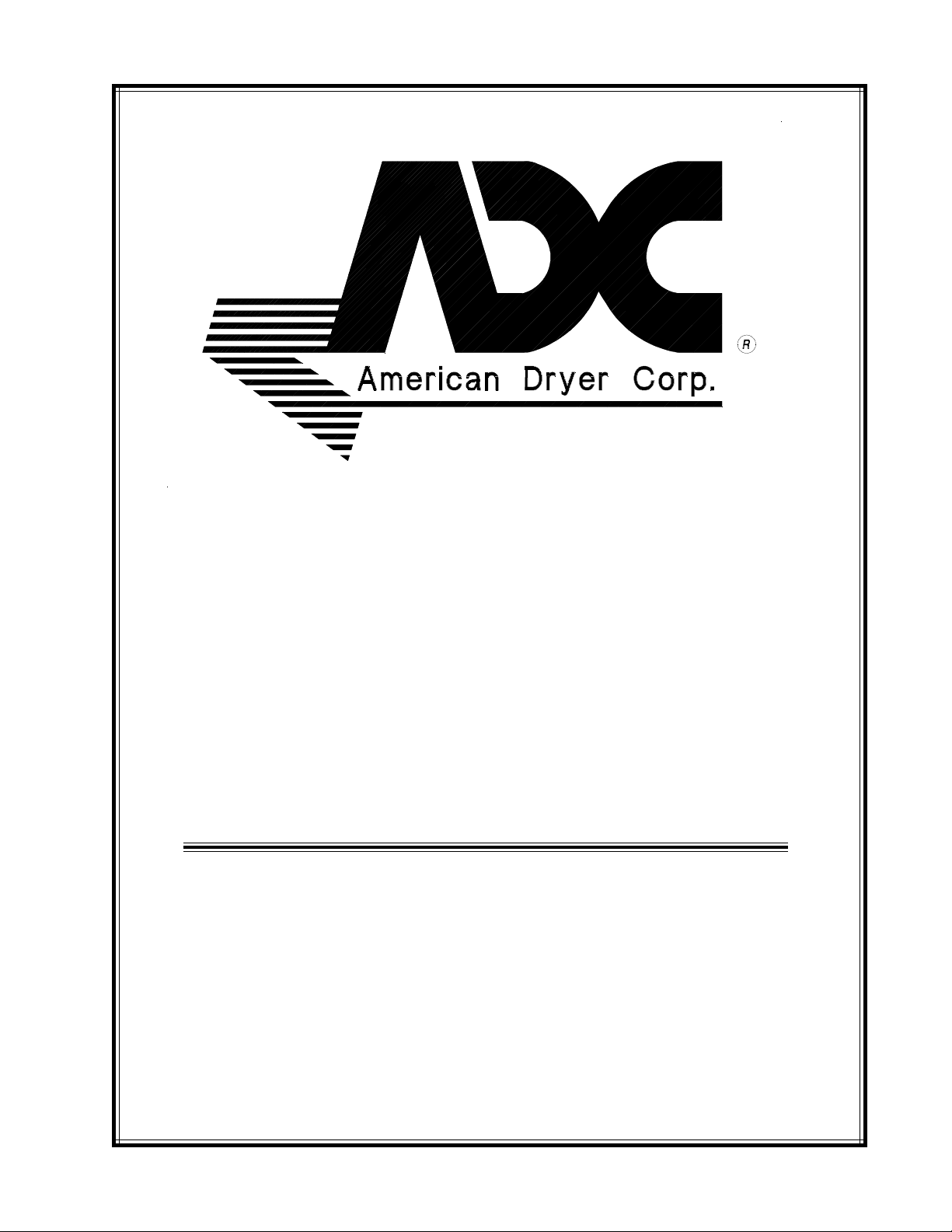
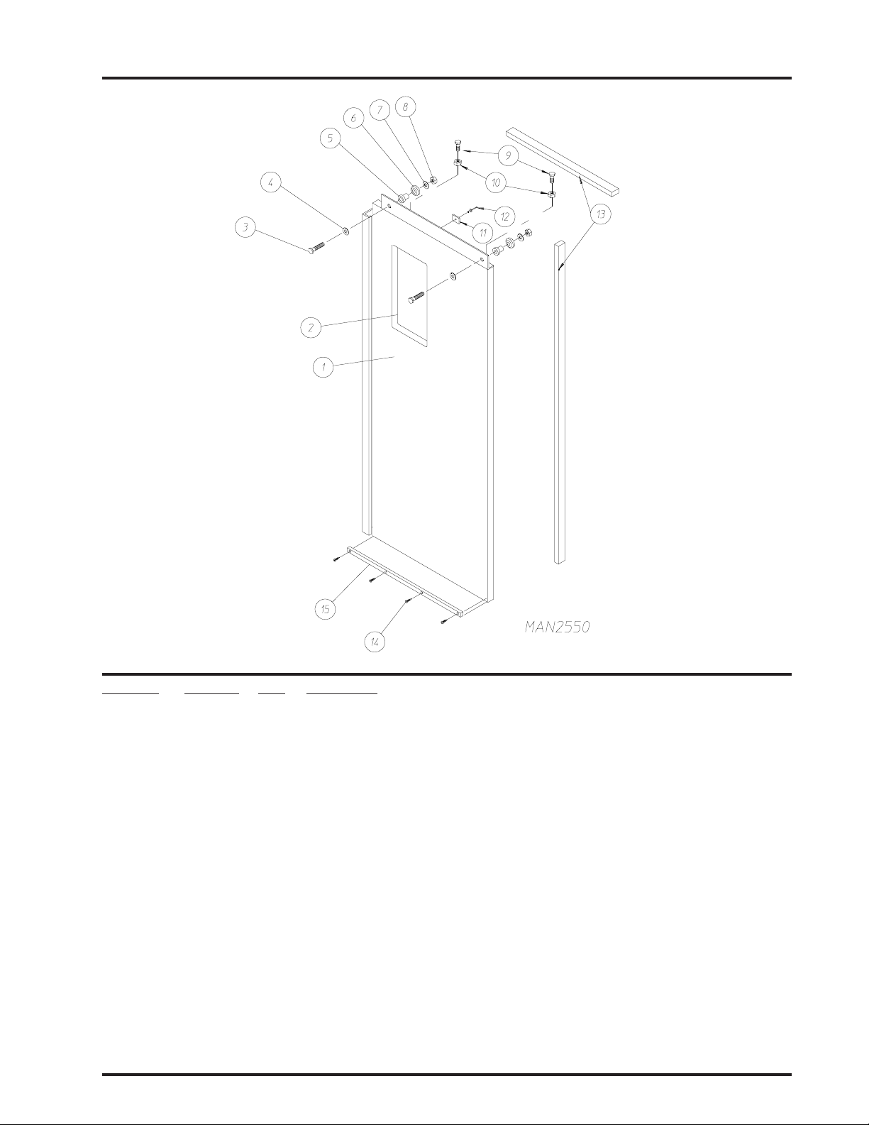
Front Panel Assembly
Automatic Door
Illus. No. Part No. Qty. Description
1* 332680 1 Left Gusset
(for gas models Only)
2 150522 15 1/4-20 x 1/2” Hex Washer Head Machine Screw
(for gas models Only)
3* 332681 2 Right Gusset
(for gas models Only)
4* 332679 1 Top Front Panel
(for gas models Only)
5* 826033 1 Upper Guard
American Dryer Corporation 88 Currant Road / Fall River, MA 02720-4781
Page 7

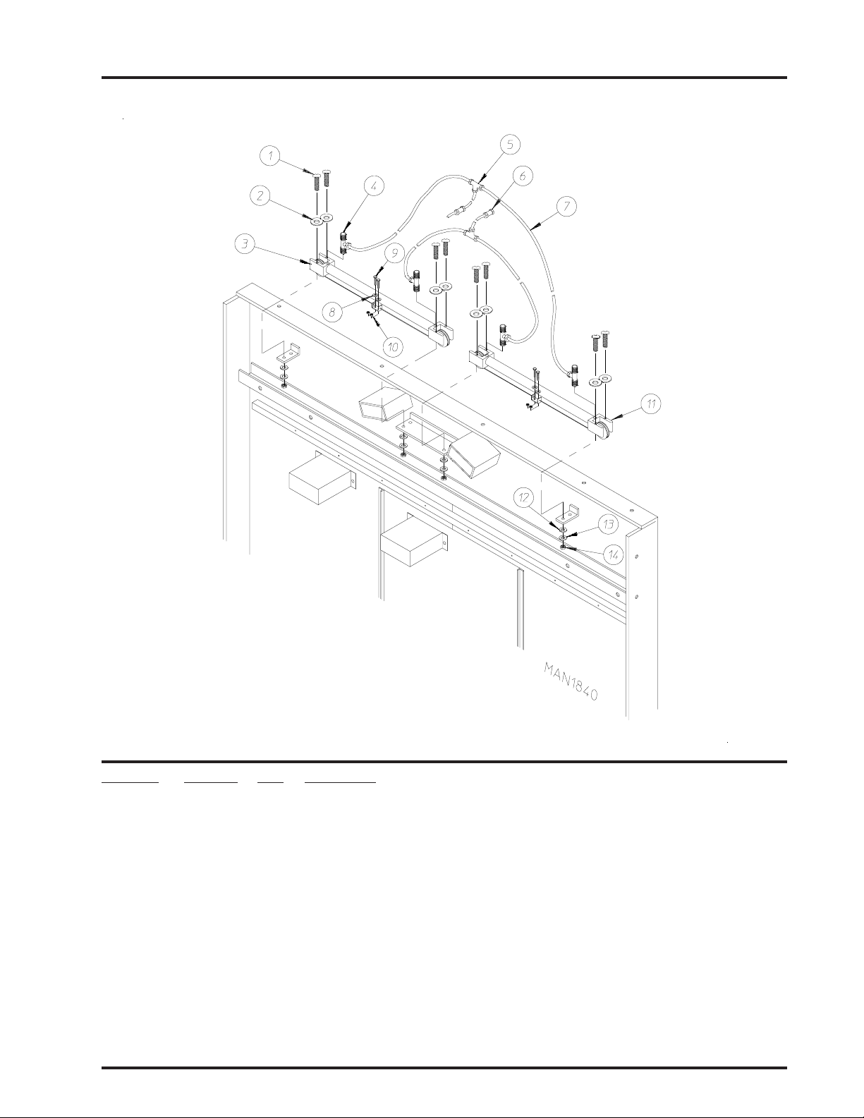
Front Panel Assembly (continued)
Automatic Door
Illus. No. Part No. Qty. Description
6* 821239 1 Middle Guard
7* 8 8 11 1 7 1 Left Control Cabinet
8* 821285 1 Bottom Guard
9 153001 8 5/16” Flat Washer
10 153002 8 5/16” Lock Washer
1 1 150501 8 5/16-18 x 3/4” Hex Head Machine Bolt
12 150510 12 1/4-20 x 3/4” Hex Head Machine Bolt
13 153007 12 1/4” Lock Washer
14 153018 12 1/4” Flat Washer
15 170364 1 Bottom Door Track
16* 88 1 1 16 1 Right Control Cabinet
17 154312 14 #10-32 x 3/4” Socket Head Cap Screw
18 170364 1 Bottom Door Track
19 -------- - Basket (tumbler) Retaining Wheel
(refer to Basket [Tumbler] Retaining Wheel Assembly on page 36)
20 150523 5 1/4-20 x 3/4” Hex Washer Machine Bolt
21 150617 8 3/8-16 x 1” Hex Head Bolt
22 153005 8 3/8” Lock Washer
23 153004 8 3/8” Flat Washer
24 * 88 110 9 1 Front Panel Assembly
25 150501 12 5/16-18 x 3/4” Hex Head Machine Bolt
26 153002 12 5/16” Lock Washer
27 153001 12 5/16” Flat Washer
28 116009 180 Felt (sold by the inch)
401010 1 Construction Mastic
29 152011 4 1/2-13 Hex Nut
30 153050 8 1/2 x 1-1/16” Flat Washer
31 153026 4 1/2” Lock Washer
32 150605 4 1/2-13 x 1-1/2” Hex Head Bolt
33 170365 1 Upper Door Track
34 153007 12 1/4” Lock Washer
35 152002 12 1/4-20 Hex Nut
36 154312 15 #10-32 x 3/4” Socket Head Cap Screw
37* 821244 2 Basket (tumbler) Retaining Wheel Cover
38 153018 12 1/4” Flat Washer
39 150523 5 1/4-20 x 3/4” Hex Washer Machine Bolt
5
* Specify color when ordering.
Telephone: (508) 678-9000 Fax: (508) 678-9447
Page 8
6
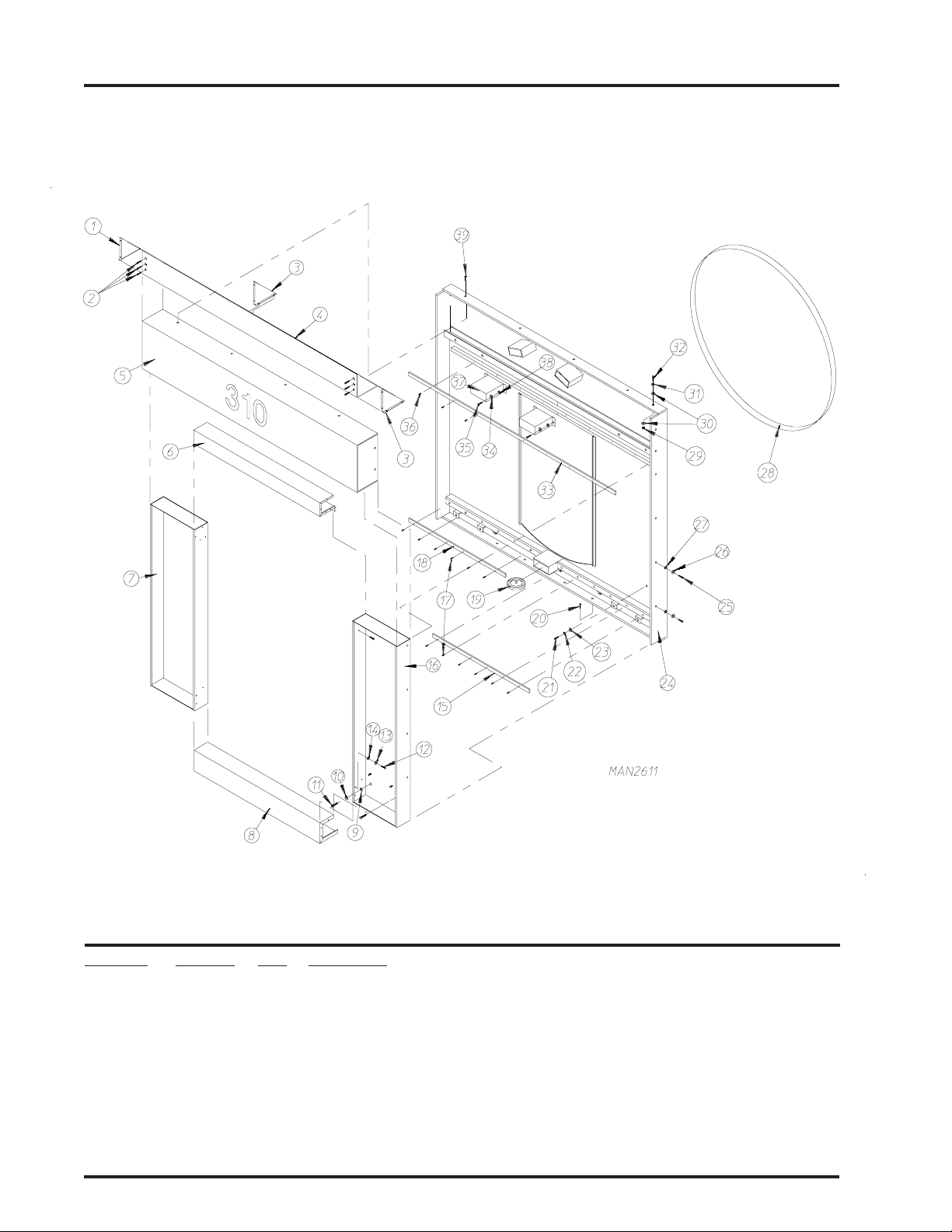
Front Panel Assembly
Manual Door
Illus. No. Part No. Qty. Description
1* 332680 1 Left Gusset
(for gas models Only)
2 150522 15 1/4-20 x 1/2” Hex Washer Head Machine Screw
(for gas models Only)
3* 826033 1 Upper Guard
4* 332681 2 Right Gusset
(for gas models Only)
5* 332679 1 Top Front Panel
(for gas models Only)
American Dryer Corporation 88 Currant Road / Fall River, MA 02720-4781
Page 9

Front Panel Assembly (continued)
Manual Door
Illus. No. Part No. Qty. Description
6* 821239 1 Middle Guard
7* 88 1 117 1 Left Control Cabinet
8* 821285 1 Bottom Guard
9 153001 8 5/16” Flat Washer
10 150501 8 5/16-18 x 3/4” Hex Head Machine Bolt
1 1 153002 8 5/16” Lock Washer
12 150510 12 1/4-20 x 3/4” Hex Head Machine Bolt
13 153007 12 1/4” Lock Washer
14 153018 12 1/4” Flat Washer
15* 88 1 1 16 1 Right Control Cabinet
16 -------- - Basket (tumbler) Retaining Wheel
(refer to Basket [Tumbler] Retaining Wheel Assembly on page 36)
17 150523 5 1/4-20 x 3/4” Hex Washer Machine Bolt
18 150617 8 3/8-16 x 1” Hex Head Bolt
19 153005 8 3/8” Lock Washer
20 153004 8 3/8” Flat Washer
21* 881108 1 Front Panel
22 150501 12 5/16-18 x 3/4” Hex Head Machine Bolt
23 153002 12 5/16” Lock Washer
24 153001 12 5/16” Flat Washer
25 116009 180 Felt (sold by the inch)
401010 1 Construction Mastic
26 152011 4 1/2-13 Hex Nut
27 153050 8 1/2 x 1-1/16” Flat Washer
28 153026 4 1/2” Lock Washer
29 150605 4 1/2-13 x 1-1/2” Hex Head Bolt
30 170365 1 Upper Door Track
31 153007 12 1/4” Lock Washer
32 152002 12 1/4-20 Hex Nut
33 154312 15 #10-32 x 3/4” Socket Head Cap Screw
34* 821244 2 Basket (tumbler) Retaining Wheel Cover
35 153018 12 1/4” Flat Washer
36 150523 5 1/4-20 x 3/4” Hex Washer Machine Bolt
7
* Specify color when ordering.
Telephone: (508) 678-9000 Fax: (508) 678-9447
Page 10
8
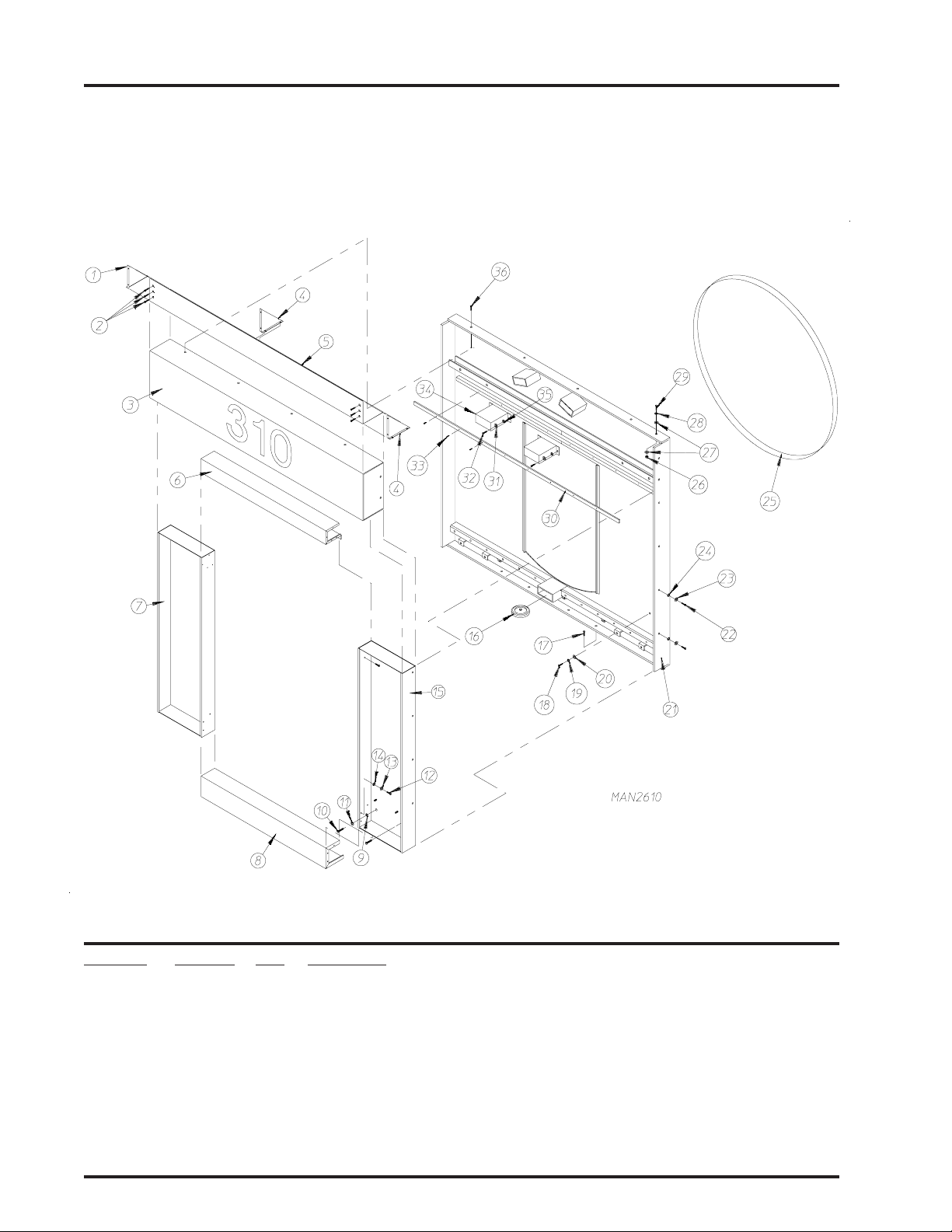
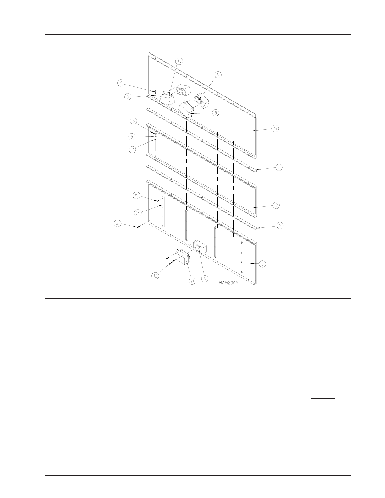
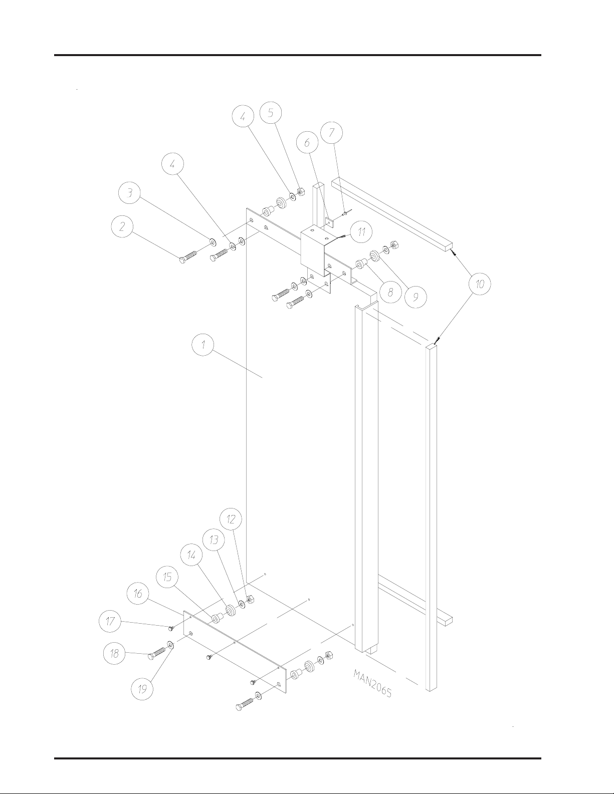
Rear Panel Assembly
1 Door/Forward Tilt
Illus. No. Part No. Qty. Description
1* 821310 1 Bottom Panel Assembly
2 -------- - Basket (tumbler) Retaining Wheel
(refer to Basket [tumbler] Retaining Wheel Assembly on page 36)
3* 332787 1 Basket (tumbler) Retaining Wheel Guard
4 150301 6 #8-18 x 7/16” Phillips Pan Head TEK Screw
5 150523 32 1/4-20 x 3/4” Hex Washer Machine Bolt
6 332571 2 Rear Panel Reinforcement
7* 821312 1 Middle Back Panel Assembly
8 152004 14 5/16-18 Hex Nut
9 153002 14 5/16” Lock Washer
10 153001 28 5/16” Flat Washer
11 150625 14 5/16-18 x 1-1/4” Hex Head Bolt
12* 150301 8 #8-18 x 7/16” Phillips Pan Head TEK Screw
13* 821244 2 Basket (tumbler) Retaining Wheel Cover
14* 881118 1 Top Back Panel Assembly
* Specify color when ordering.
American Dryer Corporation 88 Currant Road / Fall River, MA 02720-4781
Page 11
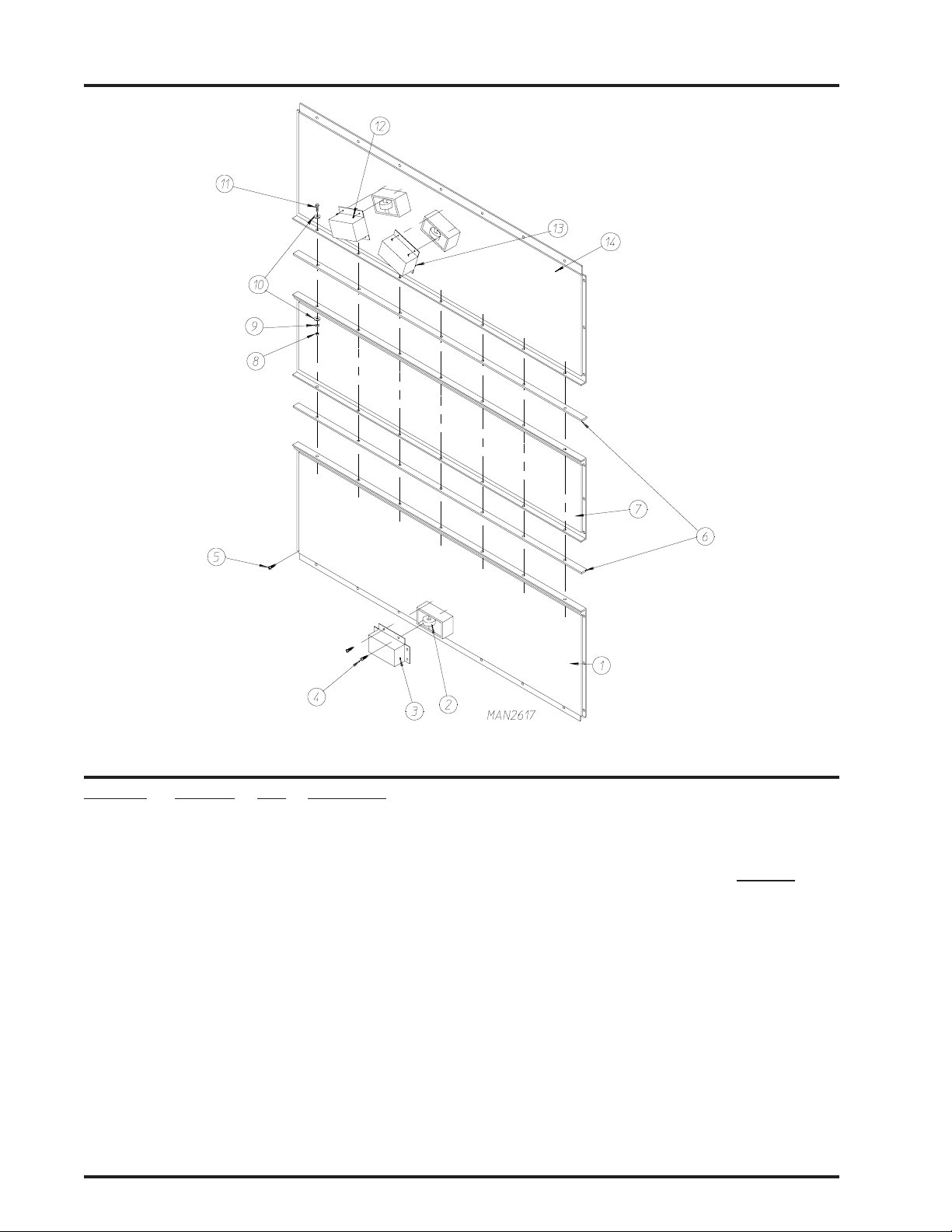
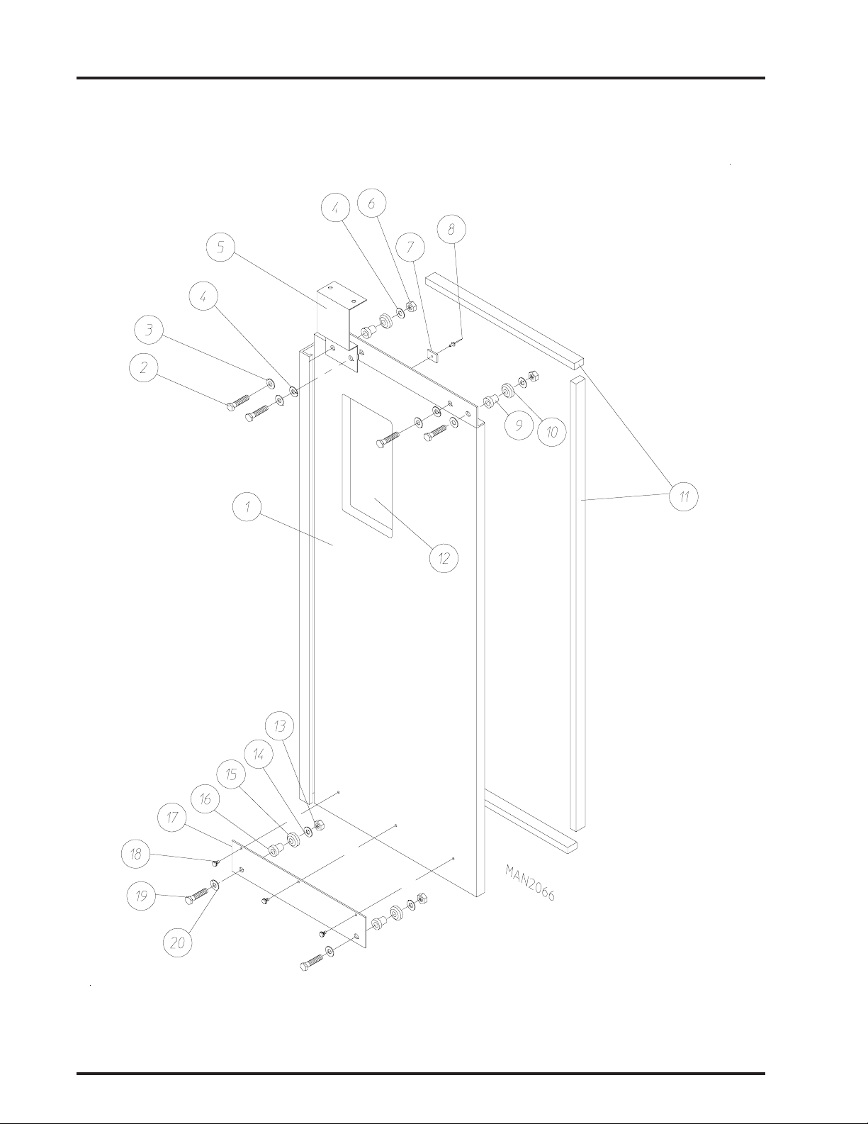
Rear Panel Assembly
1 Door/2-W ay Tilt
9
Illus. No. Part No. Qty. Description
1* 821310 1 Bottom Back Panel Assembly
2 332571 2 Rear Panel Reinforcement
3* 821312 1 Middle Back Panel Assembly
4 150625 14 5/16-18 x 1-1/4” Hex Head Machine Bolt
5 153001 28 5/16” Flat Washer
6 153002 14 5/16” Lock Washer
7 152004 14 5/16-18 Hex Nut
8* 821244 2 Basket (tumbler) Retaining Wheel Cover
9 --------- 3 Basket (tumbler) Retaining Wheel
(refer to Basket [Tumbler] Retaining Wheel Assembly on page 36)
10 150301 8 #8-18 x 7/16” Phillips Pan Head TEK Screw
11 * 332787 1 Basket (tumbler) Retaining Wheel Guard
12 150301 6 #8-18 x 7/16” Phillips Pan Head TEK Screw
13* 881118 1 Top Back Panel Assembly
14 170346 4 Nylon Guide
15 150309 16 #10-16 x 1/2” Phillips Round Head Crimptite Screw
16 150523 32 1/4-20 x 3/4” Hex Washer Machine Bolt
* Specify color when ordering.
Telephone: (508) 678-9000 Fax: (508) 678-9447
Page 12
10
Rear Panel Assembly
2 Automatic Doors
Illus. No. Part No. Qty. Description
1* 332680 1 Left Gusset
(for gas models Only)
2 150522 15 1/4-20 x 1/2” Hex Washer Head Machine Screw
(for gas models Only)
3* 332681 2 Right Gusset
(for gas models Only)
4* 332679 1 Top Front Panel
(for gas models Only)
5* 826033 1 Upper Guard
American Dryer Corporation 88 Currant Road / Fall River, MA 02720-4781
Page 13

Rear Panel Assembly (continued)
2 Automatic Doors
Illus. No. Part No. Qty. Description
6* 821239 1 Middle Guard
7* 88 1 117 1 Left Control Cabinet
8* 821285 1 Bottom Guard
9 153001 8 5/16” Flat Washer
10 153002 8 5/16” Lock Washer
1 1 150501 8 5/16-18 x 3/4” Hex Head Machine Bolt
12 150510 12 1/4-20 x 3/4” Hex Head Machine Bolt
13 153007 12 1/4” Lock Washer
14 153018 12 1/4” Flat Washer
15 170364 1 Bottom Door Track
16* 88 1 1 16 1 Right Control Cabinet
17 154312 14 #10-32 x 3/4” Socket Head Cap Screw
18 170364 1 Bottom Door Track
19 -------- - Basket (tumbler) Retaining Wheel
(refer to Basket [Tumbler] Retaining Wheel Assembly on page 36)
20 150523 5 1/4-20 x 3/4” Hex Washer Machine Bolt
21 150617 8 3/8-16 x 1” Hex Head Bolt
22 153005 8 3/8” Lock Washer
23 153004 8 3/8” Flat Washer
24* 881109 1 Front Panel
25 150501 12 5/16-18 x 3/4” Hex Head Machine Bolt
26 153002 12 5/16” Lock Washer
27 153001 12 5/16” Flat Washer
28 116009 180 Felt (sold by the inch)
401010 1 Construction Mastic
29 152011 4 1/2-13 Hex Nut
30 153050 8 1/2 x 1-1/16” Flat Washer
31 153026 4 1/2” Lock Washer
32 150605 4 1/2-13 x 1-1/2” Hex Head Bolt
33 170365 1 Upper Door Track
34 153007 12 1/4” Lock Washer
35 152002 12 1/4-20 Hex Nut
36 154312 15 #10-32 x 3/4” Socket Head Cap Screw
37* 821244 2 Basket (tumbler) Retaining Wheel Cover
38 153018 12 1/4” Flat Washer
39 150523 5 1/4-20 x 3/4” Hex Washer Machine Bolt
11
* Specify color when ordering.
Telephone: (508) 678-9000 Fax: (508) 678-9447
Page 14
12
Rear Panel Assembly
2 Manual Doors
Illus. No. Part No. Qty. Description
1* 332680 1 Left Gusset
(for gas models Only)
2 150522 15 1/4-20 x 1/2” Hex Washer Head Machine Screw
(for gas models Only)
3* 826033 1 Upper Guard
4* 332681 2 Right Gusset
(for gas models Only)
5* 332679 1 Top Front Panel
(for gas models Only)
American Dryer Corporation 88 Currant Road / Fall River, MA 02720-4781
Page 15

Rear Panel Assembly (continued)
2 Manual Doors
Illus. No. Part No. Qty. Description
6* 821239 1 Middle Guard
7* 88 1 117 1 Left Control Cabinet
8* 821285 1 Bottom Guard
9 153001 8 5/16” Flat Washer
10 150501 8 5/16-18 x 3/4” Hex Head Machine Bolt
1 1 153002 8 5/16” Lock Washer
12 150510 12 1/4-20 x 3/4” Hex Head Machine Bolt
13 153007 12 1/4” Lock Washer
14 153018 12 1/4” Flat Washer
15* 88 1 1 16 1 Right Control Cabinet
16 -------- - Basket (tumbler) Retaining Wheel
(refer to Basket [Tumbler] Retaining Wheel Assembly on page 36)
17 150523 5 1/4-20 x 3/4” Hex Washer Machine Bolt
18 150617 8 3/8-16 x 1” Hex Head Bolt
19 153005 8 3/8” Lock Washer
20 153004 8 3/8” Flat Washer
21* 881108 1 Front Panel
22 150501 12 5/16-18 x 3/4” Hex Head Machine Bolt
23 153002 12 5/16” Lock Washer
24 153001 12 5/16” Flat Washer
25 116009 180 Felt (sold by the inch)
401010 1 Construction Mastic
26 152011 4 1/2-13 Hex Nut
27 153050 8 1/2 x 1-1/16” Flat Washer
28 153026 4 1/2” Lock Washer
29 150605 4 1/2-13 x 1-1/2” Hex Head Bolt
30 170365 1 Upper Door Track
31 153007 12 1/4” Lock Washer
32 152002 12 1/4-20 Hex Nut
33 154312 15 #10-32 x 3/4” Socket Head Cap Screw
34* 821244 2 Basket (tumbler) Retaining Wheel Cover
35 153018 12 1/4” Flat Washer
36 150523 5 1/4-20 x 3/4” Hex Washer Machine Bolt
13
* Specify color when ordering.
Telephone: (508) 678-9000 Fax: (508) 678-9447
Page 16
14
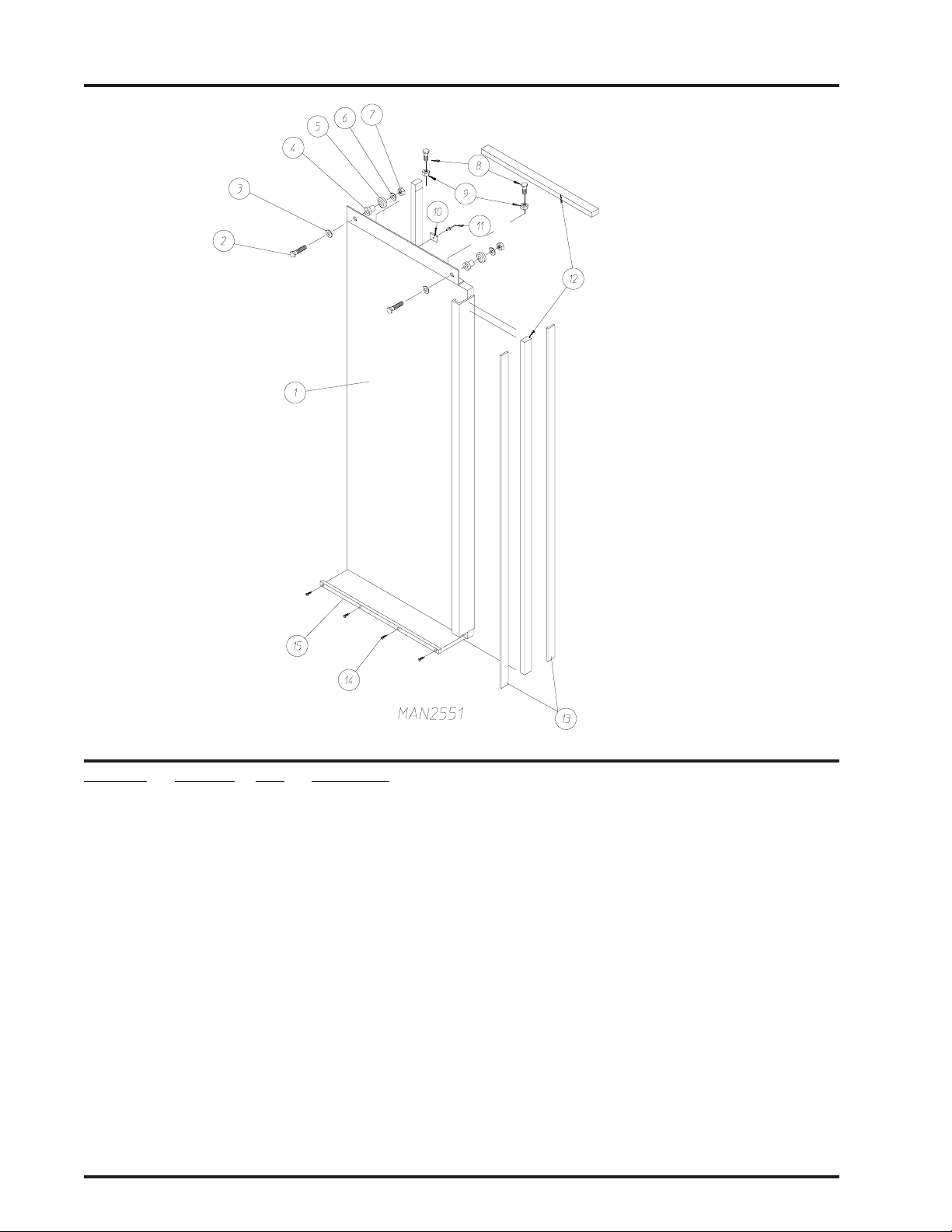
Left Load Door Assembly
Manual Door
Illus. No. Part No. Qty. Description
1* 821728 1 Left Manual Load Door Assembly Complete
(includes illus. nos. 1 through 15)
2 150112 2 1/4-20 x 1-1/4” Hex Head Machine Screw
3 153018 2 1/4” Flat Washer
4 170367 2 Stainless Steel Stationary Bushing
5 170366 2 Stainless Steel Sealed Wheel
6 153007 4 1/4” Lock Washer
7 152002 2 1/4-20 Hex Nut
8 150512 2 1/4-20 x 1/2” Hex Head Machine Bolt
9 152002 2 1/4-20 Hex Nut
10 102102 1 D o o r Magnet
11 154200 1 5/32” Pop Rivet
12 115995 125 Felt Gasket (sold by the inch)
13 102111 2 Door Mag net
14 150301 4 #8-18 x 7/16” Phillips Pan Head TEK Screw
15 170357 1 Lower Door Slide
* Specify color when ordering.
American Dryer Corporation 88 Currant Road / Fall River, MA 02720-4781
Page 17
Right Load Door Assembly
Manual Door
15
Illus. No. Part No. Qty. Description
1* 821727 1 Right Manual Load Door Assembly Complete
(includes illus. nos. 1 through 15)
2 102215 1 Door Window
170730 - Door W indow Adhesive (10.3 oz. cartridge)
3 150112 2 1/4-20 x 1-1/4” Hex Head Machine Screw
4 153018 2 1/4” Flat Washer
5 170367 2 Stainless Steel Stationary Bushing
6 170366 2 Stainless Steel Sealed Wheel
7 153007 2 1/4” Lock Washer
8 152002 2 1/4-20 Hex Nut
9 150512 2 1/4-20 x 1/2” Hex Head Machine Bolt
10 152002 2 1/4-20 Hex Nut
11 102102 1 Door Ma g n e t
12 154200 1 5/32” Pop Rivet
13 115995 80 Felt Gasket (sold by the inch)
14 150301 4 #8-18 x 7/16” Phillips Pan Head TEK Screw
15 170357 1 Lower Door Slide
* Specify color when ordering.
Telephone: (508) 678-9000 Fax: (508) 678-9447
Page 18
16
Left Load Door Assembly
Automatic Door
American Dryer Corporation 88 Currant Road / Fall River, MA 02720-4781
Page 19

Left Load Door Assembly
Automatic Door
Illus. No. Part No. Qty. Description
1* 88 1112 1 Left Automatic Load Door Assembly Complete
(includes illus. nos. 1 through 11)
881106 1 Left Automatic Load Door ONLY
2 150112 4 1/4-20 x 1-1/4” Hex Head Machine Screw
3 153018 4 1/4” Flat Washer
4 153007 4 1/4” Lock Washer
5 152002 2 1/4-20 Hex Nut
6 102102 1 Door Magnet
7 154200 1 5/32” Pop Rivet
8 170367 2 Stainless Steel Stationary Bushing
9 170366 2 Stainless Steel Sealed Wheel
10 115995 125 Felt Gasket (sold by the inch)
11 * 334134 1 Automatic Door Bracket
12 152002 2 1/4-20 Hex Nut
13 153007 2 1/4” Lock Washer
14 170366 2 Stainless Steel Sealed Wheel
15 170367 2 Stainless Steel Stationary Bushing
16 * 8 81 13 3 1 Lower Trolley Assembly Complete
(includes illus. nos. 12 through 16, 18, and 19)
334123 1 Lower Trolley ONLY
17 150301 3 #8-18 x 7/16” Phillips Pan Head TEK Screw
18 150112 2 1/4-20 x 1-1/4” Hex Head Machine Screw
19 153018 2 1/4” Flat Washer
17
* Specify color when ordering.
Telephone: (508) 678-9000 Fax: (508) 678-9447
Page 20
18
Right Load Door Assembly
Automatic Door
American Dryer Corporation 88 Currant Road / Fall River, MA 02720-4781
Page 21

Right Load Door Assembly
Automatic Door
Illus. No. Part No. Qty. Description
1* 8 8 11 1 3 1 Right Automatic Load Door Assembly Complete
(includes illus. nos. 1 through 12)
88 110 7 1 Right Automatic Load Door ONLY
2 150112 4 1/4-20 x 1-1/4” Hex Head Machine Screw
3 153018 4 1/4” Flat Washer
4 153007 4 1/4” Lock Washer
5* 334134 1 Automatic Door Bracket
6 152002 2 1/4-20 Hex Nut
7 102102 1 Door Magnet
8 154200 1 5/32” Pop Rivet
9 170367 2 Stainless Steel Stationary Bushing
10 170366 2 Stainless Steel Sealed Wheel
1 1 115995 80 Felt Gasket (sold by the inch)
12 102215 1 Door W indow
170730 - Door W indow Adhesive (10.3 oz. cartridge)
13 152002 2 1/4-20 Hex Nut
14 153007 2 1/4” Lock Washer
15 170366 2 Stainless Steel Sealed Wheel
16 170367 2 Stainless Steel Stationary Bushing
17 * 881 1 33 1 Lower Trolley Assembly Complete
(includes illus. nos. 13 through 17, 19, and 20)
334123 1 Lower Trolley ONLY
18 150301 3 #8-18 x 7/16” Phillips Pan Head TEK Screw
19 152112 2 1/4-20 x 1-1/4” Hex Head Machine Screw
20 153018 2 1/4” Flat Washer
19
* Specify color when ordering.
Telephone: (508) 678-9000 Fax: (508) 678-9447
Page 22
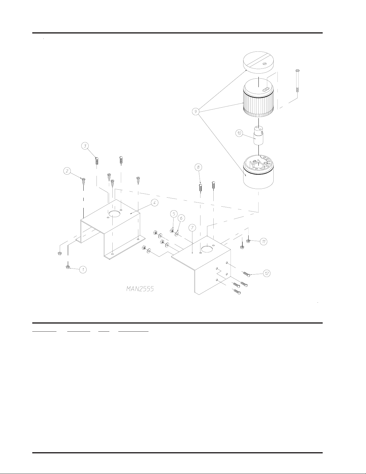
20
End of Cycle Light Assembly
Illus. No. Part No. Qty. Description
1 151001 2 #8-32 Pal Nut
2 150415 4 #10-16 x 1/2” Phillips Round Head Crimptite Screw
3 150108 2 #8-32 x 1/2” Phillips Pan Head Machine Screw
4* 821480 1 Cycle Light Bracket (for steam models Only)
5 152001 4 #8-32 Hex Nut
6 153012 4 # 8 Star Washer
7* 332850 1 Cycle Light Bracket (for gas models Only)
8 150108 2 #8-32 x 1/2” Phillips Pan Head Machine Screw
9 123222 1 “Orange” Cycle Light
10 123221 1 Bulb - 24 VAC
1 1 151001 2 #8-32 Pal Nut
12 150108 4 #8-32 x 1/2” Phillips Pan Head Machine Screw
* Specify color when ordering.
American Dryer Corporation 88 Currant Road / Fall River, MA 02720-4781
Page 23
Pneumatic Assembly
Automatic Door
21
Illus. No. Part No. Qty. Description
1 150308 8 #8-32 x 2-1/2” Phillips Pan Head Machine Screw
2 153000 8 #8 Flat Washer
3 100431 1 Cable Cylinder
4 128978 4 1/8” N.P.T. x 1/4” Tube Flow Control
5 143156 2 1/4” Poly Tee
6 143154 2 1/4” Brass Poly Connector
7 143110 38 1/4” Poly-Flo T ubing (sold by the foot)
8 153012 4 # 8 Star Washer
9 150103 4 #8-32 x 3/4” Phillips Round Head Machine Screw
10 152001 4 #8-32 Hex Nut
1 1 100431 1 Cable Cylinder
12 153000 8 #8 Flat Washer
13 153012 8 # 8 Star Washer
14 152001 8 #8-32 Hex Nut
Telephone: (508) 678-9000 Fax: (508) 678-9447
Page 24

22
Magnetic Door Switch Assembly
Illus. No. Part No. Qty. Description
1 826514 4 Magnetic Door Switch Assembly with Nuts
(includes illus. nos. 1 through 3)
2 122598 1 2-Pin Connector (male)
3 137028 2 Pin
4 137021 4 Microprocessor Socket
5 122599 2 2-Pin Socket Connector (female)
6 881240 1 Door Switch “Closed Position” Harness
(includes illus. nos. 4 through 8)
7 122598 1 2-Pin Connector (male)
8 137028 2 Pin
9 881241 1 Door Switch “Open Position” Harness
(includes illus. nos. 9 through 13)
10 122598 1 2-Pin Connector (male)
1 1 137028 2 Pin
12 122599 2 2-Pin Socket Connector (female)
13 137021 4 Microprocessor Socket
American Dryer Corporation 88 Currant Road / Fall River, MA 02720-4781
Page 25
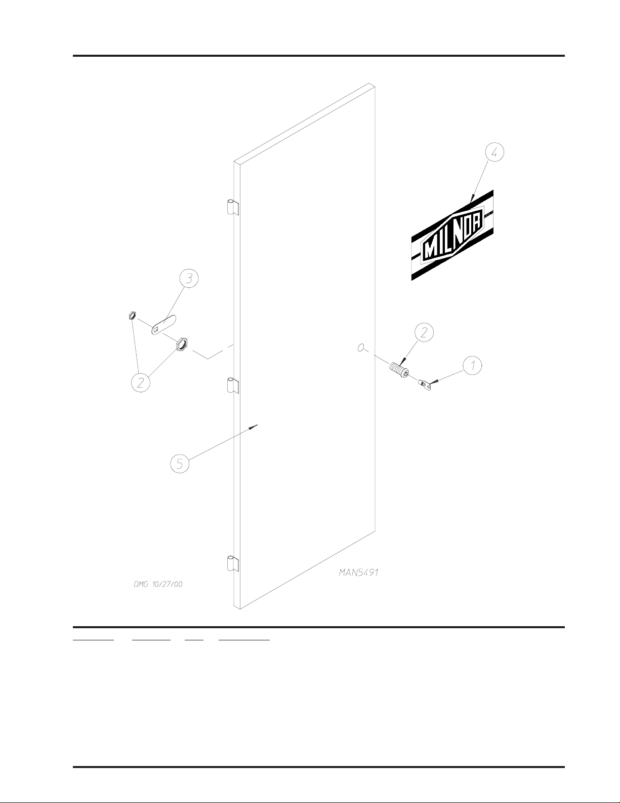
Left Control Door Assembly
For 1 Door or 2 Door Models
23
Illus. No. Part No. Qty. Description
1 160140 1 ACE® XX4451 Key ONLY
2 160050 1 ACE® Control Door Lock ONLY Less Key (keyed to #XX4451)
3 160014 1 Cam ONLY
4 112368 1 Milnor Logo ONLY (tape kit not included)
870011 1 Logo Double Tape Kit
5* 821334 1 Left Hand Control Door
* Specify color when ordering.
Telephone: (508) 678-9000 Fax: (508) 678-9447
Page 26
24
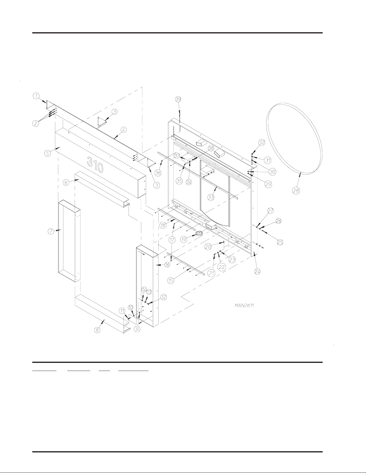
Front Contr ol Door Assembly
Illus. No. Part No. Qty. Description
1 821597 1 Front Right Control Door ONL Y
2 --------- 1 Front Right Control Door Panel ONLY
(refer to Right Rear/Front Control Panel on page 80)
3 122438 1 Engraved Nameplate: Load - Dry - Unload
4 122361 1 3-Position Maintained Operator
5 123203 1 Black Push Button Operator
6 122415 1 Engraved Nameplate: Forward
7 122416 1 Engraved Nameplate: Reverse
8 123202 1 White Push Button Operator
9 122413 1 Engraved Nameplate: Tilt Of f - Tilt On
10 122360 1 2-Position Maintained Operator
1 1 132396 2 Mounting Base with Normally Opened (N.O.) and Normally Closed (N.C.)
Contact Block
12 132394 2 Mounting Base with Normally Opened (N.O.) Contact Block
American Dryer Corporation 88 Currant Road / Fall River, MA 02720-4781
Page 27

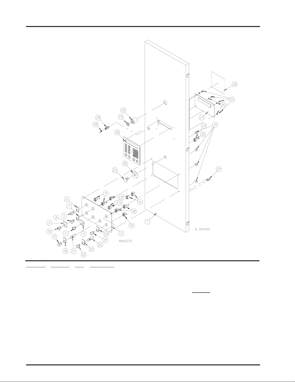
Front Control Door Assembly (continued)
Illus. No. Part No. Qty. Description
13 132386 1 Normally Opened (N.O.) Contact Block
14 132387 4 Normally Closed (N.C.) Contact Block
15 123201 1 Green Lighted Push Button Operator
16 122410 1 Engraved Nameplate: ON
17 123212 1 24 V olt Lamp
18 132388 2 Normally Opened (N.O.) Contact Block with Direct Supply
19 132395 1 Mounting Base with Normally Closed (N.C.) Contact Block
20 122421 1 Engraved Nameplate: OFF
21 123204 1 Red Push Button Operator
22 122420 1 Sprinkler Stop Nameplate
23 123200 1 Amber Lighted Push Button Operator
24 123212 1 24 V olt Lamp
25 122351 1 “EMERGENCY STOP” (E-Stop) Operator
26 122419 1 Engraved “EMERGENCY STOP” (E-Stop) Label
27 121509 6 Tie Wrap Clips
28 112571 1 Phase 7 Keyboard (touch pad)
29 134018 1 Alarm Horn Volume Control
30 128967 1 80-90 Decibel Panel Mount Alarm Horn
31 152014 4 1/4-20 Free Spin Wash Nuts
32 132395 1 Mounting Base with Normally Closed (N.C.) Contact Block
33 132387 1 Normally Closed (N.C.) Contact Block
34 153010 4 #6 Star Washer
35 150005 4 #6-32 x 1/4” Phillips Round Head Machine Screw
36 122426 1 Caution Label
37 882896 1 Phase 7 Display Board
(for models mfd. as of October 2000)
882894 1 Phase 7 Microprocessor Control Computer
(for models mfd. prior to October 2000)
38 160140 1 ACE® XX4451 Key ONLY
39 160050 1 ACE® Control Door Lock Less Key (keyed to #XX4451)
25
Telephone: (508) 678-9000 Fax: (508) 678-9447
Page 28

26
Right Rear Control Door Assembly
2 Door Models ONLY
American Dryer Corporation 88 Currant Road / Fall River, MA 02720-4781
Page 29

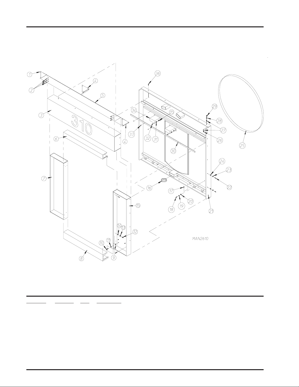
Right Rear Control Door Assembly
2 Door Models ONLY
Illus. No. Part No. Qty. Description
1 814364 1 Right Rear Control Door ONLY
2 --------- 1 Right Rear Door Control Panel
(refer to Right Rear/Front Control Panel on page 80)
3 122438 1 Load/Dry/Unload Nameplate
4 122361 1 3-Position Maintained Operator
5 123202 1 White Push Button Operator
6 122360 1 2-Position Maintained Operator
7 122413 1 Tilt Off Tilt On Nameplate
8 123203 1 Black Push Button Operator
9 122416 1 Nameplate “Reverse”
10 122415 1 Nameplate “Forward”
11 122419 1 “EMERGENCY STOP” (E-Stop) Label
12 122351 1 “EMERGENCY STOP” (E-Stop) Operator
13 132394 1 Mounting Base with Normally Opened (N.O.) Contact Block
14 132386 1 Normally Opened (N.O.) Contact Block
15 132387 2 Normally Closed (N.C.) Contact Block
16 132394 1 Mounting Base with Normally Opened (N.O.) Contact Block
17 132396 1 Mounting Base with Normally Opened (N.O.) and Normally Closed (N.C.)
Contact Block
18 132396 1 Mounting Base with Normally Opened (N.O.) and Normally Closed (N.C.)
Contact Block
19 132395 1 Mounting Base with Normally Closed (N.C.) Contact Block
20 132387 1 Normally Closed (N.C.) Contact Block
21 152014 4 1/4-20 with 3/4” Free Spin Wash Nut
22 121509 6 Tie Wrap Clips
23 160140 1 ACE
24 160050 1 ACE® Control Door Lock Less Key (keyed to #XX4451)
25 160014 1 Cam ONLY
®
XX4451 Key ONLY
27
Telephone: (508) 678-9000 Fax: (508) 678-9447
Page 30

28
Side Panel Assemblies
Illus. No. Part No. Qty. Description
1* 826035 1 Left Top Side Panel
2 150523 14 1/4-20 x 3/4” Hex Washer Machine Screw
3* 881189 1 Lower Side Panel For Hinged Doors
4 150523 16 1/4-20 x 3/4” Hex Washer Machine Screw
5* 881190 1 Locking Hinged Side Panel Door Less Locks
6 160034 2 Lock Cam ONLY
7 160050 2 ACE® Door Lock ONLY Less Key (keyed to #XX4451)
8 160140 2 ACE® XX4451 Key ONLY
9* 88 119 1 1 Hinged Side Panel Door Assembly
10* 826035 1 Right Top Side Panel (for natural gas and steam models Only)
1 1 150523 14 1/4-20 x 3/4” Hex Washer Machine Screw
12* 881189 1 Lower Side Panel For Hinged Doors
13 160050 2 ACE® Door Lock ONLY Less Key (keyed to #XX4451)
14 160140 2 ACE® XX4451 Key ONLY
15 160034 2 Lock Cam ONLY
16* 881190 1 Locking Hinged Side Panel Door Less Locks
17 * 88 1191 1 Hinged Side Panel Door Assembly
18 150523 16 1/4-20 x 3/4” Hex Washer Machine Screw
19* 826034 1 Top Right Side Panel (for liquid propane [L.P.] gas models Only)
* Specify color when ordering.
American Dryer Corporation 88 Currant Road / Fall River, MA 02720-4781
Page 31

Left Hand Electrical Control Panel Assembly
For Models Mfd. with Thermal-Magnetic Protection ONLY
29
Telephone: (508) 678-9000 Fax: (508) 678-9447
Page 32

30
Left Hand Electrical Control Panel Assembly
For Models Mfd. with Thermal-Magnetic Protection ONLY
Illus. No. Part No. Qty. Description
1 334269 1 Left Hand Electrical Panel
832677 1 Left Hand Electrical Panel Assembly Complete
(includes illus. nos. 1 through 20)
2 112075 1 Ground Label
3 114007 1 Danger High Voltage Label
4 -------- 1 Auxiliary Contact Block For Gas and Steam Models
(refer to Chart For Left Hand Electrical Panel on
5 -------- 1 Manual Starter/Thermal-Magnetic Breaker For Gas and Steam Models
(refer to Chart For Left Hand Electrical Panel on page 82)
6 -------- 1 Reversing Contactor For Gas and Steam Models
(refer to Chart For Left Hand Electrical Panel on page 82)
7 132437 2 Varistor
8 120768 8 35 x 15mm Din Mounting Rail
9 150300 2 #10-16 x 1/2” Hex Washer TEK Screw
10 120768 3 35 x 15mm Din Mounting Rail
11 150300 2 #10-16 x 1/2” Hex Washer TEK Screw
12 132494 1 Sprinkler Contactor (for dryer with sprinkler option Only)
13 120768 2 35 x 15mm Din Mounting Rail
14 150300 2 #10-16 x 1/2” Hex Washer TEK Screw
15 120765 2 End Stops
16 -------- 1 2-Pole Circuit Breaker For Gas and Steam Models
(refer to Chart For Left Hand Electrical Panel on page 82)
17 120727 1 Ground Terminal Block
18 150300 1 #10-16 x 1/2” Hex Washer TEK Screw
19 120770 2 End Bracket 12mm
20 120768 4 35 x 15mm Din Mounting Rail
page 82)
American Dryer Corporation 88 Currant Road / Fall River, MA 02720-4781
Page 33

Right Hand Electrical Control Panel
31
Illus. No. Part No. Qty. Description
1 821833 1 Front Right Electrical Panel ONLY
2 150334 4 3/8” Flat Washer
3 153005 4 3/8” Split Lock Washer
4 152005 4 3/8-16 Hex Nut
5 121422 28” 1 ” Wire Duct Cover
6 121430 28” 1” x 3” Slotted W all Wire Duct
7 121422 31” 1 ” Wire Duct Cover
8 121430 31” 1” x 3” Slotted W all Wire Duct
9 121422 12” 1 ” Wire Duct Cover
10 121430 12” 1” x 3” Slotted W all Wire Duct
11 120777 10 2-Position Terminal Block Jumper
12 120771 4 2-Position Gray Line Block
13 120776 6 Small Insulator for 2-Position Block
14 120778 2 4-Position Gray Line Block
15 120801 2 Large Insulator for 4-Position Block
16 ------- 1 Circuit Breaker #7
(refer to Right Hand Electrical Control Panel Chart on page 81)
17 ------- 1 Circuit Breaker #6
(refer to Right Hand Electrical Control Panel Chart on
page 81)
Telephone: (508) 678-9000 Fax: (508) 678-9447
Page 34

32
Illus. No. Part No. Qty. Description
18 120773 3 2-Position Green/Yellow Ground Block
19 120772 2 2-Position Blue Neutral Block
20 120765 2 End Stop
21 120768 6 35 x 15mm Din Mounting Rail
22 150300 3 #10-16 x 1/2” Hex Washer TEK Screw
23 122424 1 Power Warning Label
24 150300 4 #10-16 x 1/2” Hex Washer TEK Screw
25 --------- 1 Transformer Assembly
26 882895 1 Phase 7 Input/Output (I/O) Board
882894 1 Phase 7 Microprocessor Control Computer
27 120768 28 35 x 15mm Din Mounting Rail
28 120765 2 End Stop
29 882892 1 Auto Door TSX 07 PLC
882893 1 Main Manual Door TSX 07 PLC
30 150005 4 #6-32 x 1/4” Phillips Round Head Machine Screw
31 153010 4 # 6 Star Washer
32 150300 4 #10-16 x 1/2” Hex Washer TEK Screw
33 120768 12” 35 x 15mm Din Mounting Rail
34 120765 2 End Stop
35 120776 1 Small Insulator for 2-Position Block
36 120771 21 2-Position Gray Line Block
37 120801 4 Large Insulator for 4-Position Block
38 120778 13 4-Position Gray Line Block
39 120773 3 2-Position Green/Yellow Ground Block
40 120772 1 2-Position Blue Neutral Block
41 401024 4 Marking Tags
42 120768 12” 35 x 15mm Din Mounting Rail
43 120776 1 Small Insulator for 2-Position Block
44 120773 1 2-Position Green/Yellow Ground Block
45 120765 2 End Stops
46 120801 7 Large Insulator for 4-Position T erminal Block
47 120778 32 4-Position Gray Line Block
48 120779 3 4-Position Blue Neutral Block
49 120771 9 2-Position Gray Line Block
50 120805 10 4-Position Terminal Block Jumper
51 401024 4 Marking Tags
52 136109 1 2-Amp 250v (fast acting) Fuse
53 136016 1 5-Amp 250v (fast acting) Fuse
Right Hand Electrical Contr ol Panel (continued)
(refer to Right Hand Electrical Control Panel Chart on page 81)
(for models mfd. as of October 2000)
(for models mfd. prior to October 2000)
American Dryer Corporation 88 Currant Road / Fall River, MA 02720-4781
Page 35

Base Main Electrical Junction Box Assembly
For Models Mfd. with Thermal-Magnetic Protection ONLY
33
Telephone: (508) 678-9000 Fax: (508) 678-9447
Page 36

34
Base Main Electrical Junction Box Assembly
For Models Mfd. with Thermal-Magnetic Protection ONLY
Illus. No. Part No. Qty. Description
1 120770 2 End Bracket
2 120760 3 Terminal Block
3 131957 1 Circuit Breaker #4 (25-40 amp manual starter)
4 -------- 1 Auxiliar y Contact Block
(refer to Chart For Right Hand Electrical Control Panel on
5 -------- 1 Manual Starter
(refer to Chart For Right Hand Electrical Control Panel on
6 -------- 1 Auxiliar y Contact Block
(refer to Chart For Right Hand Electrical Control Panel on page 81)
7 114007 1 Danger High Voltage Label
8 120727 2 Ground Terminal Block
9 120768 8 35 x 15mm Din Mounting Rail
10 150300 4 #10 x 1/2” Hex Washer TEK Screw
1 1 120750 1 Ground T erminal Block (for sprinkler option)
12 120758 2 2-Position Feed Thru T erminal Block (for sprinkler option)
13 120765 2 Standard End Stop
14 -------- 1 Varistor
(refer to Chart For Right Hand Electrical Control Panel on page 81)
15 -------- 1 Contactor
(refer to Chart For Right Hand Electrical Control Panel on page 81)
16 120768 8 35 x 15mm Din Mounting Rail
17 150300 4 #10 x 1/2” Hex Washer TEK Screw
18 331499 1 Panel ONLY
19 112075 1 Ground Here Label
page 81)
page 81)
American Dryer Corporation 88 Currant Road / Fall River, MA 02720-4781
Page 37

Idler Shaft and Basket (T umbler) Assembly
35
Illus. No. Part No. Qty. Description
1 826017 1 Basket (tumbler) Assembly (for 1 door models)
826046 1 Basket (tumbler) Assembly (for 2 door models)
2 821465 2 Drive Wheel Assembly
3 101227 2 SK x 1-1/2” Bushing
4 880880 2 1-1/2” Pillow Block Bearing with Setscrews and Grease Fitting
814489 2 External Grease Fitting Kit
5 150620 4 1/2-13 x 2-1/2” Hex Head Machine Bolt
6 153011 4 9/16” Flat Washer
7 153011 4 9/16” Flat Washer
8 153026 4 1/2” Lock Washer
9 152011 4 1/2-13 Hex Nut
10 170511 2 1/8-27 N.P.T. Grease Fitting
11 150609 2 1/2-13 x 4-1/2” Hex Head Machine Bolt
12 152011 2 1/2-13 Hex Nut
13 334057 1 1-1/2” Diameter Idler Shaft
14 100710 2 3/8” x 3/8” x 3” Key
15 154200 2 5/32” Pop Rivet
16 102102 2 Magnet
17 333152 1 Phase 7 Rotational Sensor Bracket
18 882633 1 Rotational Sensor Proximity Switch
19 150309 1 #10-16 x 1/2” Hex Head Crimptite TEK
20 333163 1 Magnet Plate For Rotational Sensor
Telephone: (508) 678-9000 Fax: (508) 678-9447
Page 38

36
Basket (T umbler) Retaining Wheel Assembly
Illus. No. Part No. Qty. Description
1* --------- 1 Basket (tumbler) Retaining Wheel Cover/Guard
(refer to appropriate Front Panel Assembly or Rear Panel Assembly)
2 150301 4 #8-18 x 7/16” Phillips Pan Head TEK Screw
3 820566 1 Basket (tumbler) Retaining Wheel Assembly
4 152004 1 5/16-18 Hex Nut
5 150509 1 5/16-18 x 3” Hex Head Machine Bolt
6 153002 1 5/16” Lock Washer
7 153001 1 5/16” Flat Washer
* Specify color when ordering.
American Dryer Corporation 88 Currant Road / Fall River, MA 02720-4781
Page 39

Lint Drawer/Basket Assembly
37
Illus. No. Part No. Qty. Description
1* 826119 1 Stainless Steel Screened Lint Basket Assembly
(includes illus. nos. 1 and 2)
For Models Mfd. as of August 14, 2000
881497 1 Lint Draw Assembly Complete
(includes illus. nos. 1 and 2)
For Models Mfd. prior to August 14, 2000
2 117602 7 Noise Suppressor Tape (sold by the foot)
3 108214 1 Lint Screen Assembly
(for models mfd. prior to August 14, 2000)
4 122116 1 Lint Drawer/Basket Switch ONLY
5 122605 2 4-Pin Socket Connector ONLY
6 122701 4 Socket Terminal ONLY
122801 1 Pin/Socket Extraction Tool
7 800264 1 Lint Drawer/Basket Switch Box Assembly Complete
(includes illus. nos. 4 through 7)
304034 1 Lint Drawer/Basket Switch Cover ONLY
8 150301 4 #8-18 x 7/16” Phillips Pan Head TEK Screw
9 122700 4 Pin Terminal ONL Y
10 122604 2 4-Pin Connector ONLY
1 1 150301 2 #8-18 x 7/16” Phillips Pan Head TEK Screw
* Specify color when ordering.
Telephone: (508) 678-9000 Fax: (508) 678-9447
Page 40

38
T emperatur e Sensor Bracket Assembly
Illus. No. Part No. Qty. Description
1 820967 1 Sensor Bracket Assembly
820968 1 Sensor Bracket Assembly Complete
(includes illus. nos. 1 through 10)
2 150000 2 #6-32 x 1/4” Slotted Round Head Machine Screw
3 153010 2 # 6 Star Washer
4 130112 1 225° Thermostat ONLY
5 152000 2 #6-32 Hex Nut
6 121028 2 1/4” x 0.032 Insulated Terminal
7 122701 4 Socket Terminal ONLY
8 122605 1 4-Pin Socket Connector (female)
9 154007 2 1/4” Push On Fastener
10 880251 1 1/4” Temperature Sensor Probe Assembly
(includes illus. nos. 6 through 10)
1 1 150301 4 #8-18 x 7/16” Phillips Pan Head TEK Screw
American Dryer Corporation 88 Currant Road / Fall River, MA 02720-4781
Page 41

Basket (T umbler) Drive Shaft Assembly
39
Telephone: (508) 678-9000 Fax: (508) 678-9447
Page 42

40
Illus. No. Part No. Qty. Description
1 821465 2 11” Drive Wheel Assembly
2 101227 2 SK x 1-1/2” Taper Lock Bushing
3 880880 2 1-1/2” Pillow Block Bearing with Grease Fitting
814489 2 External Grease Fitting Kit
170511 2 1/8-27 N.P.T. Grease Fitting
4 153011 4 9/16” Flat Washer
5 150620 4 1/2-13 x 2-1/2” Hex Head Machine Bolt
6 101023 1 1-1/2” T aper Bushing
7 153011 4 9/16” Flat Washer
8 153026 4 1/2” Lock Washer
9 152011 4 1/2-13 Hex Nut
10 101019 1 Taper Bore Speed Reducer
11 101 1 7 7 1 2B x 5.8 Pulley
12 100709 1 3/8” x 3/8” x 2” Key
13 10119 6 1 SDS x 1-5/8” Bushing
14 334058 1 Basket (tumbler) Drive Shaft
15 150609 2 1/2-13 x 4-1/2” Hex Head Machine Bolt
16 152011 2 1/2-13 Hex Nut
17 154395 1 Gear Reducer Turnbuckle
18 100710 2 3/8” x 3/8” x 3” Key
19* 100152 1 AX-25 V-Belt (for 60 Hz models Only)
100160 1 AP-26 V-Belt (for 50 Hz models Only)
Basket (T umbler) Drive Shaft Assembly
* Replace in matched sets (both belts).
American Dryer Corporation 88 Currant Road / Fall River, MA 02720-4781
Page 43

T ilt Switch Assembly
41
NOTE: One (1) Assembly Required for 1-Way Tilt Models
T wo (2) Assemblies Required for 2-W ay Tilt Models
Illus. No. Part No. Qty. Description
1 881252 1 Tilt Switch Assembly Complete
(includes illus. nos. 1, 2, and 4)
122365 1 Limit Switch Rotary Head
2 122369 1 Tilt Switch Arm
3 150211 4 #10-32 x 2” Round Head Machine Screw
4 122367 1 Tilt Switch Body
5 153009 4 #10 Star Washer
6 152008 4 #10-32 Hex Nut
Telephone: (508) 678-9000 Fax: (508) 678-9447
Page 44

42
T ilt Piston Assembly
2-W ay Tilt
Illus. No. Part No. Qty. Description
1 100559 1 5” Bore x 14” Stroke Piston
2 143283 1 3/8” Poly x 3/8” M.P.T. Connector
3 143221 1 3/8” Brass Poly Tee
4 143120 20 3/8” Poly Tubing (sold by the foot)
5 143213 1 3/8” Poly x 3/8” M.P.T. Brass Elbow
6 334309 2 Cylinder Pin Nylon Bumper
7 150435 4 3/8-16 x 3” Socket Head Cap Screw
8 100553 1 Rod Eye
9 154315 2 1/4-20 x 1” Socket Head Setscrew
10 331543 1 1” Pin
1 1 150599 4 1/2-20 x 1-1/4” Hex Head Machine Bolt
12 153026 4 1/2” Lock Washer
13 153011 4 9/16” Flat Washer
14 881 170 1 Clevis Assembly
American Dryer Corporation 88 Currant Road / Fall River, MA 02720-4781
Page 45

Post Assembly
43
Illus. No. Part No. Qty. Description
1 100487 1 3/4” Diagram Pin (with cotter pin)
2 881529 1 Post Assembly
3 100553 1 Rod Eye
4 154315 2 1/4-20 x 1” Socket Head Setscrew
5 334309 2 Cylinder Pin Nylon Bumper
6 150435 4 3/8-16 x 3” Socket Head Cap Screw
7 331543 1 Rod Eye Pin
8 150599 4 1/2-20 x 1-1/8” Hex Head Bolt
9 153026 4 1/2” Lock Washer
10 881 170 1 Clevis Assembly
Telephone: (508) 678-9000 Fax: (508) 678-9447
Page 46

44
Drive Motor Assembly
Illus. No. Part No. Qty. Description
1 101144 1 SH x 1-1/8” Bushing
2 101187 1 2B x 3.6 Motor Pulley (for 60 Hz models Only)
10 119 5 1 2B x 4.4 Motor Pulley (for 50 Hz models Only)
3* 100152 2 AX-25 V-Belt (for 60 Hz models Only)
100160 2 AX-26 V-Belt (for 50 Hz models Only)
4 100705 1 3/16” x 3/16” x 1-3/8” Key
5 181020 1 5 HP Multi-V oltage 190-208/230/380-460 Volt 3ø 50/60 Hz
6 153004 4 3/8” Flat Washer
7 153005 4 3/8” Lock Washer
8 150600 4 3/8” x 1-1/2” Hex Head Machine Bolt
* Replace in matched sets (both belts).
American Dryer Corporation 88 Currant Road / Fall River, MA 02720-4781
Page 47

Fan Motor Assembly
For Gas Models ONLY
45
Telephone: (508) 678-9000 Fax: (508) 678-9447
Page 48

46
Illus. No. Part No. Qty. Description
1 100062 1 Motor Base (213T frame)
2 153004 4 3/8” Flat Washer
3 153005 4 3/8” Lock Washer
4 150617 4 3/8-16 x 1” Hex Head Machine Bolt
5 153004 4 3/8” Flat Washer
6 153005 4 3/8” Lock Washer
7 152005 4 3/8-16 Hex Nut
8 100087 1 15 HP 208-230/380/460 Volt 3ø 60 Hz Motor
and 190-220/380-416 Volt 3ø 50 Hz Motor
9* 100161 2 BX-47 V-Belt
10 10119 5 1 2B x 4.4 Pulley (for 60 Hz models Only)
101202 1 2B x 5.2 Pulley (for 50 Hz models Only)
11 101 1 52 1 SH x 1-3/8” Bushing (for 60 Hz models Only)
10 119 4 1 SDS x 1-3/8” Bushing (for 50 Hz models Only)
12 100717 1 5/16” x 5/16” x 2-3/4” Key
13 10118 4 1 SK x 1-3/8” Bushing
14 101201 1 2B x 9.4 Pulley
15 150600 2 3/8-16 x 1-1/2” Hex Head Machine Bolt
16 100802 1 1-3/8” Retaining Ring
(for models mfd. prior to November 7, 1996)
17 880879 1 1-3/8” Shrouded Pillow Block Bearing
(includes illus. nos. 17 and 18)
814488 2 External Grease Fitting Kit
18 170511 1 Grease Fitting
19 153004 2 3/8” Flat Washer
20 153005 2 3/8” Lock Washer
21 332703 1 Fan (impellor/blower) Shaft
22 100802 1 1-3/8” Retaining Ring
23 880879 1 1-3/8” Shrouded Pillow Block Bearing
(includes illus. nos. 23 and 26)
24 150600 2 3/8-16 x 1-1/2” Hex Head Machine Bolt
25 116014 1 Felt Seal
26 170511 1 Grease Fitting
27 153004 2 3/8” Flat Washer
28 153005 2 3/8” Lock Washer
29 100653 1 18” Diagram Squirrel Cage Fan
30 153065 1 Fan Washer
31 152006 2 1/2-20 Left Hand Jam Nut
32 100704 1 1/4” x 1/4” x 1-3/4” Key
33 881503 1 Fan (impellor/blower) Shaft Bearing Mount Assembly
34 153004 4 3/8” Flat Washer
35 150617 4 3/8-16 x 1” Hex Head Machine Bolt
36 153005 4 3/8” Lock Washer
Fan Motor Assembly
For Gas Models ONLY
* Replace in matched sets (both belts).
American Dryer Corporation 88 Currant Road / Fall River, MA 02720-4781
Page 49

Fan Motor Assembly
For S team Models ONL Y
47
Telephone: (508) 678-9000 Fax: (508) 678-9447
Page 50

48
Illus. No. Part No. Qty. Description
1 181007 1 Motor Base (256T frame)
2 153014 4 1/2” Flat Washer
3 153026 4 1/2” Lock Washer
4 150605 4 1/2-13 x 1-1/2” Hex Head Machine Bolt
5 153004 4 3/8” Flat Washer
6 153005 4 3/8” Lock Washer
7 152005 4 3/8-16 Hex Nut
8 181006 1 25 HP 208-230/380/460 Volt 3ø 60 Hz Motor
and 190-220/380-416 Volt 3ø 50 Hz Motor
9* 100128 2 BX-50 V-Belt
10 10116 7 1 2B x 6.0 Pulley (for 60 Hz models Only)
10 118 5 1 2B x 6.2 Pulley (for 50 Hz models Only)
11 1 0 119 6 1 SDS x 1-5/8” Bushing
12 100709 1 3/8” x 3/8” x 3” Key
13 10115 0 1 SK x 1-1/2” Bushing
14 10114 5 1 2B x 1 1.0 Pulley (for 60 Hz models Only)
101201 1 2B x 9.4 Pulley (for 50 Hz models Only)
15 150606 2 1/2-13 x 2” Hex Head Machine Bolt
16 100804 1 1-1/2” Retaining Ring
17 880942 1 1-1/2” Shrouded Pillow Block Bearing
(includes illus. nos. 17 and 18)
814488 2 External Grease Fitting Kit
18 170511 1 Grease Fitting
19 153014 2 1/2” Flat Washer
20 153026 2 1/2” Lock Washer
21 334206 1 Fan (impellor/blower) Shaft
22 100804 1 1-1/2” Retaining Ring
23 880942 1 1-1/2” Shrouded Pillow Block Bearing
(includes illus. nos. 23 and 26)
24 150606 2 1/2-13 x 2” Hex Head Machine Bolt
25 116014 1 Felt Seal
26 170511 1 Grease Fitting
27 153014 2 1/2” Flat Washer
28 153026 2 1/2” Lock Washer
29 100653 1 18” Diagram Squirrel Cage Fan
30 153065 1 Fan Washer
31 152006 2 1/2-20 Left Hand Jam Nut
32 100704 1 1/4” x 1/4” x 1-3/4” Key
33 881513 1 Fan (impellor/blower) Shaft Bearing Mount Assembly
34 153004 6 3/8” Flat Washer
35 153005 6 3/8” Lock Washer
36 150617 6 3/8-16 x 1” Hex Head Machine Bolt
Fan Motor Assembly
For S team Models ONL Y
* Replace in matched sets (both belts).
American Dryer Corporation 88 Currant Road / Fall River, MA 02720-4781
Page 51

Front Gas Burner Assembly
49
Telephone: (508) 678-9000 Fax: (508) 678-9447
Page 52

50
Illus. No. Part No. Qty. Description
1 141241 1 5-Port Front Manifold
2 142548 1 1” x 90° Elbow
3 150309 2 #10-16 x 1/2” Hex Head TEK Crimptite Screw
4 334085 1 Pipe Bracket
5 142724 1 1” x 2” Long Nipple
6 140017 1 1” 2 4 VA C Natural Gas Valve
140018 1 1” 24 VAC Gas Valve Liquid Propane (L.P.) Conversion Kit
7 334085 1 Pipe Bracket
8 140834 5 #5 Burner Orifice (natural gas)
140819 5 #30 Burner Orifice (liquid propane [L.P.] gas)
9 142711 1 1” Close Nipple
10 334086 1 Manifold Rest
1 1 334083 1 Front Burner Tube Rest
12 333192 1 Burner Baffle
13 150001 1 #6-32 x 1/2” Phillips Round Head Machine Screw
14 130201 1 330° Manual Hi-Limit Thermostat
15 826021 1 Hi-Limit Mounting Bracket
16 151000 2 #6-32 Pal Nut
17 331290 1 Sight Hole Disc
18 332597 1 Burner Box Cover Plate
19 141 1 3 9 5 Uginox Burner T ube
20 -------- 1 Sail Switch
(refer to Sail Switch Assembly on page 53)
21 826019 1 Front Burner Box ONLY
882888** 1 Natural Gas Front Burner Box Assembly Complete Less Orifices
(includes illus. nos. 1 through 7 and 9 through 22)
882890** 1 Liquid Propane (L.P.) Gas Front Burner Box Assembly Complete Less Orifices
(includes illus. nos. 1 through 8 and 10 through 22)
881011* 1 ADG-310 Direct Spark Ignition (DSI) Liquid Propane (L.P.) Conversion Kit
(includes orifices)
22 880943 1 Direct Spark Ignition (DSI) Ignitor/Flame-Probe Assembly
(includes high voltage [HV] wire and connector)
305410 1 Ignitor Gap Feeler Gauge ... Not Illustrated
Front Gas Burner Assembly
* Contact factory for elevations over 2,000 feet.
** Orifices are not included and must be ordered separately.
American Dryer Corporation 88 Currant Road / Fall River, MA 02720-4781
Page 53

Rear Gas Burner Assembly
51
Telephone: (508) 678-9000 Fax: (508) 678-9447
Page 54

52
Illus. No. Part No. Qty. Description
1 141242 1 5-Port Rear Manifold
2 142711 2 1” Close Nipple
3 150309 2 #10-16 x 1/2” Hex Head TEK Crimptite Screw
4 334085 1 Pipe Bracket
5 140017 1 1” 2 4 VA C Natural Gas Valve
881011 1 ADG-310 Direct Spark Igniton (DSI) Liquid Propane (L.P.) Conversion Kit
(includes orifices)
6 334085 1 Pipe Bracket
7 142724 1 1” x 2” Nipple
8* 140834 5 #5 Burner Orifice (natural gas)
140819 5 #30 Burner Orifice (liquid propane [L.P.] gas)
9 142548 1 1” x 90° Elbow
10 334086 1 Manifold Rest
11 334084 1 Rear Burner Tube Rest
12 333192 1 Burner Baffle
13 150001 1 #6-32 x 1/2” Phillips Round Head Machine Screw
14 130201 1 330° Manual Hi-Limit Thermostat
15 826021 1 Hi-Limit Mounting Bracket
16 151000 2 #6-32 Pal Nut
17 331290 1 Sight Hole Disc
18 332597 1 Burner Box Cover Plate
19 14113 9 5 Uginox Burner T ube
20 -------- 1 Sail Switch
(refer to Sail Switch Assembly on
21 827002 1 Rear Burner Box ONLY
882889** 1 Natural Gas Rear Burner Box Assembly Complete Less Orifices
(includes illus. nos. 1 through 7 and 9 through 22)
882891** 1 Liquid Propane (L.P.) Gas Rear Burner Box Assembly Complete
Less Orifices
(includes illus. nos. 1 through 7 and 9 through 22)
22 880943 1 Direct Spark Ignition (DSI) Ignitor/Flame-Probe Assembly
(includes high voltage [HV] wire and connector)
305410 1 Ignitor Gap Feeler Gauge ... Not Illustrated
Rear Gas Burner Assembly
page 53)
* Consult factory for elevations over 2,000 feet.
** Orifices are not included and must be ordered separately.
American Dryer Corporation 88 Currant Road / Fall River, MA 02720-4781
Page 55

Sail Switch Assembly
53
Illus. No. Part No. Qty. Description
1 105500 1 Sail Switch Actuator Rod
2 332689 1 Sail Switch Damper (flat)
3 154002 1 1/8” Push On Fastener
4 802800 1 Sail Switch Box with Cover and Bracket ONLY
(includes illus. nos. 4 and 8)
881376 1 Sail Switch Box Assembly Complete
(includes illus. nos. 1 through 4 and 6 through 10)
5 150300 2 #10 x 1/2” Hex Washer TEK Screw
6 150303 2 # 4 x 3/4” Pan Head “A” Machine Screw
7 122404 1 Sail Switch ONLY
8 802799 1 Sail Switch Box Cover and Bracket ONLY
9 150415 2 #10-16 x 1/2” Phillips Round Head Crimptite Screw
10 154004 1 T win Speed Nut
Telephone: (508) 678-9000 Fax: (508) 678-9447
Page 56

54
Direct Spark Ignition (DSI) Module Assembly
Illus. No. Part No. Qty. Description
1 128935 1 Direct Spark Ignition (DSI) Module ONLY - 50/60 Hz
(for models mfd. as of April 1, 2000)
880815 1 Direct Spark Ignition (DSI) Module ONLY - 50/60 Hz
(for models mfd. prior to April 1, 2000)
2 820100 1 Direct Spark Ignition (DSI) Module Mount Assembly ONLY
3 121400 2 Universal Bushing
4 150522 3 1/4-20 x 1/2” Hex Head TEK Screw
5 150301 1 #8-18 x 7/16” Phillips Pan Head TEK Screw
6 153010 4 # 6 Star Washer
7 152000 4 #6-32 Hex Nut
8 120102 2 3/8” Straight x 1/2” Knock-Out Connector
American Dryer Corporation 88 Currant Road / Fall River, MA 02720-4781
Page 57

Gas Piping Assembly
55
Telephone: (508) 678-9000 Fax: (508) 678-9447
Page 58

56
Illus. No. Part No. Qty. Description
1 142931 1 2” x 1-1/2” Double Tapped Bushing
2 150504 4 5/16-18 x 1” Hex Head Machine Bolt
3 142514 1 2” Floor Flange
4 153002 4 5/16” Lock Washer
5 152004 4 5/16-18 Hex Nut
6 142568 1 1-1/2” x 8” Nipple
7 142611 1 1-1/2” x 1-1/4” x 1/4” Tee
8 142522 1 1-1/4” x 90° Street Elbow
9 142725 2 1-1/4” x 2” Nipple
10 142558 2 1-1/4” Union
11 141416 2 1-1/4” x 48” Flex Hose (non-swivel ends)
12 150511 4 1/4-20 x 1” Hex Head Machine Bolt
13 153002 4 5/16” Lock Washer
14 152004 4 5/16-18 Hex Nut
15 333073 2 Flex Hose Bracket
16 153018 4 1/4” Flat Washer
17 153007 4 1/4” Lock Washer
18 152002 4 1/4-20 Hex Nut
19 154351 2 1-1/2” U-Bolt
20 142914 2 1-1/2” to 1-1/4” Reducing Bushing
21 142845 1 1-1/2” Side Outlet Elbow
22 142522 1 1-1/4” x 90° Elbow
23 154351 1 1-1/2” U-Bolt
24 142596 1 1-1/2” x 5” Nipple
25 142603 1 1-1/2” Union
26 333156 1 Pipe Bracket
27 150309 2 #10-16 x 1/2” Hex Head TEK Crimptite Screw
28 153002 2 5/16” Lock Washer
29 152004 2 5/16-18 Hex Nut
30 142738 1 1-1/2” x 2” Nipple
31 142915 2 1-1/2” x 45° Elbow
32 142567 1 1-1/2” x 6” Nipple
33 142738 1 1-1/2” x 2” Nipple
34 142904 1 1-1/2” x 18” Nipple
35 142512 2 1-1/2” x 90° Elbow
36 142736 1 1-1/2” x 20” Nipple
37 154351 1 1-1/2” U-Bolt
38 332533 1 Pipe Bracket
39 152004 2 5/16-18 Hex Nut
40 153002 2 5/16” Lock Washer
41 150309 2 #10-16 x 1/2” Hex Head TEK Crimptite Screw
42 142603 1 1-1/2” Union
43 142827 1 1-1/2” x 2-1/2” Nipple
Gas Piping Assembly
continued on page 57
American Dryer Corporation 88 Currant Road / Fall River, MA 02720-4781
Page 59

Gas Piping Assembly
continued from page 56
Illus. No. Part No. Qty. Description
44 142842 2 1-1/4” x 19” Nipple
45 142558 2 1-1/4” Union
46 142725 2 1-1/4” x 2” Nipple
47 142554 2 1-1/4” x 90° Elbow
48 142575 2 1-1/4” x 18” Nipple
49 142728 2 1-1/4” to 1” Reducing Elbow
50 142844 2 1” x 45° Male Elbow
51 141302 2 1” Shutoff
52 142808 2 1” x 3” Nipple
53 142602 2 1” Union
54 142841 1 1-1/4” x 1-1/4” x 1-1/2” Tee
57
Telephone: (508) 678-9000 Fax: (508) 678-9447
Page 60

58
Steam Coil Assembly
Illus. No. Part No. Qty. Description
1 165034 1 Steam Coil Assembly
2 150523 8 1/4-20 x 3/4” Hex Washer Machine Bolt
3 153007 4 1/4” Lock Washer
4 152002 4 1/4-20 Hex Nut
5 820321 2 Steam Damper Hinge Assembly
6 115995 144 Steam Damper Gasket (sold by the inch)
7 -------- 1 Steam Damper Assembly
(includes illus. nos. 6 through 8)
8 102350 2 Steam Damper Foam
9 153007 4 1/4” Lock Washer
10 152002 4 1/4-20 Hex Nut
11 151008 1 5/8-18 Stainless Steel Acorn Nut
12 152030 1 5/8-18 Jam Nut
13 100542 1 2” Bore x 4” Stroke Piston
(for models mfd. as of January 21, 1999)
882197 1 2” Bore x 4” Stroke Piston
(for models mfd. prior to January 21, 1999)
14 150523 4 1/4-20 x 3/4” Hex Washer Machine Bolt
(for models mfd. as of January 21, 1999)
152002 4 1/4-20 Hex Nut ... Not Illustrated
(for models mfd. prior to January 21, 1999)
American Dryer Corporation 88 Currant Road / Fall River, MA 02720-4781
Page 61

Steam Coil Assembly (continued)
Illus. No. Part No. Qty. Description
15 153007 4 1/4” Lock Washer
16 100544 1 Piston Support Bracket with Pivot Pin
17 143238 1 1/8” Brass Close Nipple
18 143264 1 1/4” Poly to 1/8” Brass Reducing Bushing
19 100496 1 1/8” Needle Valve
20 100472 1 1/4” Poly x 1/8” M.P.T. Connector
21 143115 - 1/4” O.D. Tubing (sold by the foot)
22 143156 1 1/4” Poly Tee
23 143115 - 1/4” O.D. Tubing (sold by the foot)
24 100472 1 1/4” Poly x 1/8” M.P.T. Connector
25 100496 1 1/8” Needle Valve
26 143264 1 1/4” Poly to 1/8” Brass Reducing Bushing
27 143238 1 1/8” Brass Close Nipple
28 100542 1 2” Bore x 4” Stroke Piston
29 151008 1 5/8-18 Stainless Steel Acorn Nut
30 153030 1 5/8-18 Jam Nut
31 150523 4 1/4-20 x 3/4” Hex Washer Machine Bolt
32 153007 2 1/4” Lock Washer
33 100544 1 Piston Support Bracket with Pivot Pin
34 150522 2 1/4-20 Hex Washer Head Machine Screw
35 153007 2 1/4” Lock Washer
36 153010 2 #6 S tar Washer
37 152000 2 #6-32 Hex Nut
38 330987 1 Micro V alve Support
39 100472 1 1/4” Poly x 1/8” M.P.T. Connector
40 100472 1 1/4” Poly x 1/8” M.P.T. Connector
41 143115 - 1/4” O.D. Tubing (sold by the foot)
42 100498 1 3-Way Micro Valve - 24 VAC
43 150002 2 #6-32 x 1” Phillips Round Head Machine Screw
44 100520 1 1/8” N.P.T. Silencer (muffler)
59
Telephone: (508) 678-9000 Fax: (508) 678-9447
Page 62

60
T ilting Steam Piping Assembly
American Dryer Corporation 88 Currant Road / Fall River, MA 02720-4781
Page 63

Tilting Steam Piping Assembly
Illus. No. Part No. Qty. Description
1 142534 1 2” x 12” Nipple
2 152004 4 5/16-18 Hex Nut
3 153002 4 5/16” Lock Washer
4 142550 1 2” x 45° Elbow
5 143125 1 2” x 72” Flex Hose
6 154352 2 2” U-Bolt
7 142747 1 1/2” Pipe Plug
8 142920 1 2” x 1/2” x 2” Tee
9 153002 4 5/16” Lock Washer
10 152004 4 5/16-18 Hex Nut
1 1 154352 1 2” U-Bolt
12 153002 2 5/16” Lock Washer
13 152004 4 5/16-18 Hex Nut
14 142991 2 2” x 36” Pipe Insulation
15 150522 2 1/4-20 x 1/2” Hex Washer Head Machine Screw
16 332533 1 Pipe Bracket
17 142835 1 2” x 4-1/2” Nipple
18 142542 1 2” Union
19 142836 1 2” x 2-1/2” Nipple
20 142550 1 2” x 45° Elbow
21 142550 1 2” x 45° Elbow
22 142556 1 1-1/4” x 12” Nipple
23 142560 1 1-1/4” x 45° Elbow
24 142836 1 2” x 2-1/2” Nipple
25 142538 1 2” x 36” Nipple
26 153002 2 5/16” Lock Washer
27 154353 2 1-1/4” U-Bolt
28 332533 1 Pipe Bracket
29 143126 1 1-1/4” x 60” Flex Hose
30 142928 1 1-1/4” Pipe Plug
31 142922 1 1-1/4” Tee
32 142559 1 1-1/4” x 6” Nipple
33 142558 1 1/4” Union
34 142725 1 1/4” x 2” Nipple
35 154353 1 1-1/4” U-Bolt
36 142725 1 1/4” x 2” Nipple
37 142726 1 1-1/4” x 24” Nipple
38 142560 2 1-1/4” x 45° Elbow
39 150522 2 1/4-20 x 1/2” Hex Washer Head Machine Screw
40 152004 2 5/16-24 Hex Nut
61
continued on page 62
Telephone: (508) 678-9000 Fax: (508) 678-9447
Page 64

62
continued from page 61
Illus. No. Part No. Qty. Description
41 153002 2 5/16” Lock Washer
42 332533 1 Pipe Bracket
43 152004 2 5/16-24 Hex Nut
44 154352 1 2” U-Bolt
45 142542 1 2” Union
46 150522 2 1/4-20 x 1/2” Hex Washer Head Machine Screw
47 154353 1 1-1/4” U-Bolt
48 332533 1 Pipe Bracket
49 153002 2 5/16” Lock Washer
50 152004 2 5/16-18 Hex Nut
51 142992 2 1-1/4” x 36” Pipe Insulation
52 150522 2 1/4-20 x 1/2” Hex Washer Head Machine Screw
53 142726 1 1-1/4” x 24” Nipple
54 142558 1 1-1/4” Union
55 142535 1 2” x 18” Nipple
56 152004 2 5/16-24 Hex Nut
57 153002 2 5/16” Lock Washer
58 332526 1 Top Pipe Bracket
59 150522 4 1/4-20 x 1/2” Hex Washer Head Machine Screw
60 142542 1 2” Union
61 142541 1 2” x 90° Elbow
62 142592 1 2” x 4” Nipple
63 142535 1 2” x 18” Nipple
64 142541 1 2” x 90° Elbow
65 154352 1 2” U-Bolt
66 142595 1 2” x 7” Nipple
67 142541 1 2” x 90° Elbow
68 152004 2 5/16-18” Hex Nut
69 153002 2 5/16” Lock Washer
70 332526 1 Top Pipe Bracket
71 150522 4 1/4-20 x 1/2” Hex Washer Head Machine Screw
72 154353 1 1-1/4” U-Bolt
73 142554 1 1-1/4” 90° Elbow
74 142729 1 1-1/4” x 8” Nipple
75 142554 1 1-1/4” 90° Elbow
76 142575 1 1-1/4” x 18” Nipple
77 142558 1 1-1/4” Union
78 142727 1 1-1/4” x 4” Nipple
79 142900 1 2” to 1-1/4” x 90° Reducing Elbow
T ilting Steam Piping Assembly
American Dryer Corporation 88 Currant Road / Fall River, MA 02720-4781
Page 65

Pneumatic Valve Assembly 1 Auto Door/2-Way Tilt w/Optional Sprinkler
63
Telephone: (508) 678-9000 Fax: (508) 678-9447
Page 66

64
Pneumatic Valve Assembly 1 Auto Door/2-Way T ilt w/ Optional Sprinkler
Illus. No. Part No. Qty. Description
1 826810 1 Pneumatic Plate ONLY
2 100498 1 3-Way MAC Valve - 24 VAC
3 100545 1 MAC Valve 24 VAC
4 100521 1 1 Auto Door Pneumatic Valve Assembly
(includes illus. nos. 2 through 5)
5 100472 2 1/4” Poly x 1/8” M.P.T. Connector
6 143149 1 1/4” Poly x 1/8” M.P.T. 90° Elbow
7 150002 2 #6-32 x 1” Phillips Round Head Machine Screw
8 153010 2 #6 Star Washer
9 143115 * 1/4” O.D. Nylo-Seal Tubing (sold by the foot)
10 153008 2 #6 Lock Washer
11 152000 2 #6-32 Hex Nut
12 100520 7 1/8” Muffler (silencer)
13 150522 6 1/4-20 x 1/2” Hex Washer
14 100479 1 Filter Regulator with Gauge
15 143213 1 3/8” Poly x 3/8” Elbow Brass
16 332624 1 3/8” Norgren Filter/Regulator Adapter Bracket
17 143153 1 1/4” Poly x 1/4” Male N.P.T. 90° Elbow
18 151001 2 #8-32 Hex Nut
19 153007 2 1/4” Lock Washer
20 121429 14” 1” x 2” Wiring Duct (sold by the inch)
21 100522 1 Double Acting Sprinkler Solenoid V alve 120 VAC
22 150008 2 #6-32 x 1-1/4” Phillips Pan Head Machine Screw
23 153010 2 #6 Star Washer
24 152000 2 #6-32 Hex Nut
25 143166 4 1/4” M.P.T. x 3/8” Poly Connector
26 150109 4 #8-32 x 2” Screw
27 153012 4 #8 Star Washer
28 100528 2 Tilting Solenoid 24 VAC, 5-Port, 3-Position
29 143165 2 1/4” M.P.T. x 1/4” Tube Connector
30 150309 5 #10-16 x 1/2” Hex Head TEK Crimptite Screw
31 143115 4 1/4” Poly-Flo T ee
American Dryer Corporation 88 Currant Road / Fall River, MA 02720-4781
Page 67

Pneumatic Valve Assembly 2 Auto Doors/1-Way T ilt w/Optional Sprinkler
65
Telephone: (508) 678-9000 Fax: (508) 678-9447
Page 68

66
Pneumatic Valve Assembly 2 Auto Door/1-Way Tilt w/Optional Sprinkler
Illus. No. Part No. Qty. Description
1 826810 1 Pneumatic Plate ONLY
2 100498 1 3-Way MAC Valve - 24 VAC
3 100545 2 MAC Valve 24 VAC
4 803402 1 2 Auto Doors Pneumatic Valve Assembly
(includes illus. nos. 2 through 5)
5 100472 2 1/4” Poly x 1/8” M.P.T. Connector
6 143149 1 1/4” Poly x 1/8” M.P.T. 90° Elbow
7 150002 2 #6-32 x 1” Phillips Round Head Machine Screw
8 153010 2 #6 Star Washer
9 143115 * 1/4” O.D. Nylo-Seal Tubing (sold by the foot)
10 153008 2 #6 Lock Washer
11 152000 2 #6-32 Hex Nut
12 100520 7 1/8” Muffler (silencer)
13 150522 6 1/4-20 x 1/2” Hex Washer
14 100479 1 Filter Regulator with Gauge
15 143213 1 3/8” Poly x 3/8” Elbow Brass
16 332624 1 3/8” Norgren Filter/Regulator Adapter Bracket
17 143153 1 1/4” Poly x 1/4” Male N.P.T. 90° Elbow
18 151001 2 #8-32 Hex Nut
19 153007 2 1/4” Lock Washer
20 121429 14” 1” x 2” Wiring Duct (sold by the inch)
21 100522 1 Double Acting Sprinkler Solenoid V alve 120 VAC
22 150008 2 #6-32 x 1-1/4” Phillips Pan Head Machine Screw
23 153010 2 #6 Star Washer
24 152000 2 #6-32 Hex Nut
25 143166 2 1/4” M.P.T. x 3/8” Poly Connector
26 150109 4 #8-32 x 2” Screw
27 153012 4 #8 Star Washer
28 100528 1 Tilting Solenoid 24 VAC, 5-Port, 3-Position
29 143165 2 1/4” M.P.T. x 1/4” Tube Connector
30 150309 5 #10-16 x 1/2” Hex Head TEK Crimptite Screw
31 143115 4 1/4” Poly-Flo T ee
* As Required.
American Dryer Corporation 88 Currant Road / Fall River, MA 02720-4781
Page 69

Air Jet Assembly
67
Illus. No. Part No. Qty. Description
1 332700 1 Air Jet Tube
2 143287 1 1/4” x 1/8” M.P.T. Tee
3 143259 1 1/4” Compression x 1/8” F.P.T. Bulkhead Fitting
4 332531 1 Air Jet Mounting Plate
5 143100 1 1/4” Aluminum Tube (sold by the foot)
6 143152 1 1/4” Compression x 1/8” M.P.T. Connector
7 152014 2 1/4-20 Free Spin Nut
8 150002 1 #6-32 x 1” Phillips Round Head Machine Screw
9 100520 1 1/8” N.P.T. Silencer/Muffler
10 100498 1 3-Way Micro V alve
1 1 100472 1 1/4” Poly x 1/8” M.P.T. Connector
12 143110 10 1/4” Poly-Flo T ubing (sold by the foot)
13 153010 2 #6 Star Washer
14 152000 2 #6-32 Hex Nut
15 150415 2 #10-16 x 1/2” Phillips Round Head Crimptite Screw
16 330987 1 Micro Valve Support Bracket
Telephone: (508) 678-9000 Fax: (508) 678-9447
Page 70

68
Optional Sprinkler Control Panel
American Dryer Corporation 88 Currant Road / Fall River, MA 02720-4781
Page 71

Optional Sprinkler Control Panel
Illus. No. Part No. Qty. Description
1 120765 2 Standard End Stop
2 120750 2 Ground Terminal Block
3 120761 8 4-Position Feed Thru T erminal Block
4 120758 7 Feed Thru Terminal Block
5 120999 5 Blank Marking Tags
6 120766 2 End Section
7 120768 16 35 x 15mm Din Mounting Rail
8 121429 12 Slotted Wall W ire Duct
9 121422 12 1” Wireway Cover
10 122424 1 Power Warning Label
11 150108 6 #8-32 x 1/2” Phillips Pan Head Machine Screw
12 132091 1 208/240v to 120v Transformer
132092 1 380/400v to 120v Transformer
132006 1 416v to 120v Transformer
132078 1 480v to 120v Transformer
13 153004 4 3/8” Flat Washer
14 153005 4 3/8” Lock Washer
15 152005 4 3/8-16 Hex Nut
16 881249 1 °C/°F Digital Temperature Controller Assembly
17 153000 6 #8 Flat Washers
18 333002 1 Sprinkler Mounting Bracket
19 334269 1 Sprinkler Panel ONLY
814332 1 Sprinkler Panel Assembly Complete
(includes illus. nos. 1 through 35)
20 131410 2 Double-Pole-Double-Throw (DPDT) Relay Socket
21 131411 4 Hold Down For Double-Pole-Double-Throw (DPDT) Relay
22 131405 2 Double-Pole-Double-Throw (DPDT) Relay with Smoked Case
23 150300 10 #10 x 3/8” Self Drilling Screw
24 120756 1 1/4” Fuse Terminal Block with Light Emitting Diode (L.E.D.)
25 120754 1 5 x 20mm Fuse Terminal Block with Light Emitting Diode (L.E.D.)
26 136039 1 1/4-Amp 5 x 20mm Fuse
27 136033 1 3-Amp Fuse
28 136050 1 1-Amp (slo blo) Fuse 208/240v ONLY
136057 1 5-Amp (slo blo) Fuse 380-460v ONLY
29 120721 2 Fused Disconnect Terminal Block
30 121422 8 1 ” Wireway Cover
31 121429 8 Slotted Wall Wire Duct
32 121429 14 Slotted Wall W ire Duct
33 121422 14 1” Wireway Cover
34 121429 4 Slotted Wall Wire Duct
35 121422 4 1 ” Wireway Cover
69
Telephone: (508) 678-9000 Fax: (508) 678-9447
Page 72

70
Optional Sprinkler Assembly
American Dryer Corporation 88 Currant Road / Fall River, MA 02720-4781
Page 73

Optional Sprinkler Assembly
Illus. No. Part No. Qty. Description
1 143135 1 48” Flex Hose
2 331794 1 Inlet Pipe Bracket
3 153007 2 1/4” Lock Washer
4 152002 2 1/4-20 Hex Nut
5 150522 2 1/4-20 x 1/2” Hex Head Washer Machine Screw
6 154350 1 1” Pipe U-Bolt
7 152002 2 1/4-20 Hex Nut
8 153007 2 1/4” Lock Washer
9 150522 2 1/4-20 x 1/2” Hex Head Washer Machine Screw
10 331794 1 Inlet Pipe Bracket
1 1 143556 1 1” Ball V alve
12 142808 1 1” x 3” Nipple
13 142548 1 1” 90° Elbow
14 142808 1 1” x 3” Nipple
15 100557 1 1” Air Operated Water Valve
16 142808 1 1” x 3” Nipple
17 143137 1 Hose Clamp
18 143136 1 1” Hose Nipple
19 142548 1 1” 90° Elbow
20 154350 1 1” Pipe U-Bolt
21 882157 12 1 Foot Aluminum Tubing
22 154353 1 1-1/4” Pipe U-Bolt
23 143210 1 1/4” Compression x 1/4” M.P.T. Elbow
24 143137 1 Hose Clamp
25 143136 1 1” Hose Nipple
26 334255 1 Pipe Bracket
27 150522 2 1/4-20 x 1/2” Hex Head Washer Machine Screw
28 152002 2 1/4-20 Hex Nut
29 153007 2 1/4” Lock Washer
30 142602 1 1” Union
31 142581 1 1” x 5” Nipple
32 142590 2 1” x 45° Elbow
33 142602 1 1” Union
34 142579 1 1” x 6” Nipple
35 142581 1 1” x 5” Nipple
36 142746 1 1” x 24” Nipple
37 154350 1 1” Pipe U-Bolt
38 334255 1 Pipe Bracket
39 152002 2 1/4-20 Hex Nut
71
continued on page 72
Telephone: (508) 678-9000 Fax: (508) 678-9447
Page 74

72
continued from page 71
Illus. No. Part No. Qty. Description
40 153007 2 1/4” Lock Washer
41 150522 2 1/4-20 x 1/2” Hex Head Washer Machine Screw
42 142602 1 1” Union
43 142746 1 1” x 24” Nipple
44 142590 2 1” 45° Elbow
45 142808 1 1” x 3” Nipple
46 142598 1 1” x 17” Nipple
47 142548 1 1” 90° Elbow
48 142808 1 1” x 3” Nipple
49 142508 6 1” Tee
50 142926 7 1” x 1/4” Reducing Bushing
51 140927 7 1/4” Sprinkler Nozzle
52 154350 1 1” Pipe U-Bolt
53 142581 1 1” x 5” Nipple
54 150309 4 #10-16 x 1/2” Hex Head TEK Crimptite Screw
55 332941 1 Sprinkler Pipe Bracket
56 153007 2 1/4” Lock Washer
57 152002 2 1/4-20 Hex Nut
58 142581 1 1” x 5” Nipple
59 150523 2 1/4-20 x 3/4” Hex Washer TEK Screw
60 331877 1 Temperature Probe Mounting Plate
61 142581 1 1” x 5” Nipple
62 142579 1 1” x 5” Nipple
63 142581 1 1” x 5” Nipple
64 154350 1 1” Pipe U-Bolt
65 142581 1 1” x 5” Nipple
66 150309 4 #10-16 x 1/2” Hex Head TEK Crimptite Screw
67 332941 1 Sprinkler Pipe Bracket
68 153007 2 1/4” Lock Washer
69 152002 2 1/4-20 Hex Nut
70 142548 1 1” x 90° Elbow
71 142584 1 1” x 4-1/2” Nipple
72 142602 1 1” Union
73 142621 1 1” x 32” Nipple with Holes
74 142591 1 1” Pipe Cap
Optional Sprinkler Assembly
American Dryer Corporation 88 Currant Road / Fall River, MA 02720-4781
Page 75

Optional Sprinkler Temperature Pr obe Junction Box Assembly
73
Illus. No. Part No. Qty. Description
1 331877 1 Temperature Sensor Mounting Plate
2 150523 2 1/4-20 x 3/4” Hex Washer Machine Screw
3 881227 1 Resistive Temperature Device (RTD) Sprinkler Temperature Probe Assembly
(includes illus. nos. 3, 4, and 8)
4 143296 1 1/4” Compression Fitting
5 120652 1 1/2” N.P.T. Cord Grip (red)
6 120915 1 1/2” N.P.T. Locknut
7 120914 1 1/2” Metal “O” Ring
8 122736 3 Yellow Ferrule
9 881228 1 Sprinkler Temperature Probe Box Assembly
(includes illus. nos. 9 and 12)
10 152000 2 #6-32 Hex Nut
11 120703 1 6-Position Terminal Block
12 122427 1 “!” Caution Label
13 150008 2 #6-32 x 1-1/4” Phillips Round Head Machine Screw
14 122736 3 Yellow Ferrule
15 120914 1 1/2” Metal “O” Ring
16 120915 1 1/2” N.P.T. Locknut
17 120650 1 1/2” N.P.T. Cord Grip (white)
18 881229 1 Sprinkler Temperature Probe Harness
Telephone: (508) 678-9000 Fax: (508) 678-9447
Page 76

74
Base Panel Assemblies
American Dryer Corporation 88 Currant Road / Fall River, MA 02720-4781
Page 77

Base Panel Assemblies
Illus. No. Part No. Qty. Description
1 334169 1 Front Base Panel
2 150522 6 1/4-20 x 1/2” Hex Washer Head Machine Screw
3 334169 1 Front Base Panel
4 150522 6 1/4-20 x 1/2” Hex Washer Head Machine Screw
5 881530 1 Left Side Base Panel
(for gas models Only)
881531 1 Left Base Panel
(for gas models with sprinkler option Only)
881532 1 Left Base Panel
(for gas models with side exhaust Only)
881533 1 Left Base Panel
(for steam models Only)
881534 1 Left Base Panel
(for steam models with side exhaust Only)
6 150522 10 1/4-20 x 1/2” Hex Washer Head Machine Screw
7 150522 6 1/4-20 x 1/2” Hex Washer Head Machine Screw
8 334158 1 Rear Right Base Panel
334234 1 Rear Right Base Panel
(for
ALL models with side exhaust Only)
9 334168 1 Rear Left Base Panel
334234 1 Rear Left Base Panel
(for ALL models with side exhaust Only)
10 150522 6 1/4-20 x 1/2” Hex Washer Head Machine Screw
11 334296 1 Right Side Rear Base Panel
(for gas models Only)
12 334066 1 Gas Inlet Base Panel
(for gas models Only)
13 150522 6 1/4-20 x 1/2” Hex Washer Head Machine Screw
14 334297 1 Right Side Front Base Panel
(for gas models Only)
15 150522 12 1/4-20 x 1/2” Hex Washer Head Machine Screw
16 334210 1 Right Side Base Panel
(for steam models Only)
17 150522 12 1/4-20 x 1/2” Hex Washer Head Machine Screw
75
Telephone: (508) 678-9000 Fax: (508) 678-9447
Page 78

76
Guard Panel Assemblies
2-W ay Tilt
American Dryer Corporation 88 Currant Road / Fall River, MA 02720-4781
Page 79

Guard Panel Assemblies
2-W ay Tilt
Illus. No. Part No. Qty. Description
1* 881200 1 Front Guard Door ONLY
2 150300 4 #10 x 1/2” Hex Washer TEK Screw
3 170606 1 Door Magnet
4* 881199 1 Front Guard Panel ONLY
(includes illus. nos. 3 through 6)
881201 1 Front Guard Assembly Complete
(includes illus. nos. 1 through 6)
5 170348 4 Front Guard Nylon Glide
6 150412 8 #10-16 x 3/4” Phillips Round Head Crimptite Screw
7* 334316 1 Side Shield Assembly
8 150522 6 1/4-20 x 1/2” Hex Washer Head Machine Screw
9* 334316 1 Side Shield Assembly
10 150522 6 1/4-20 x 1/2” Hex Washer Head Machine Screw
1 1 152002 4 1/4-20 Hex Nut
12 153007 4 1/4” Lock Washer
13 881188 2 Spring Catch Assembly
14 157014 2 Spring
15 108121 2 Rear Panel Chain
16 154354 2 3/4” Pipe U-Bolt
17* 88 1198 1 Rear Guard Assembly Complete
(includes illus. nos. 15 through 21)
For 1 Door Models ONLY
881197 1 Rear Guard ONLY
18 150309 8 #10-16 x 1/2” Hex Head TEK Crimptite Screw
19 170345 4 Nylon Glide
20 152002 8 1/4-20 Hex Nut
21 153007 4 1/4” Lock Washer
22* 881535 1 Rear Guard Assembly Complete
(includes illus. nos. 22 through 24)
For 2 Door Models ONLY
23 170348 2 Nylon Glide
24 150412 4 #10-16 x 3/4” Phillips Round Head Crimptite Screw
77
* Specify color when ordering.
Telephone: (508) 678-9000 Fax: (508) 678-9447
Page 80

78
Guard Panel Assemblies
1-W ay Tilt
Illus. No. Part No. Qty. Description
1* 881200 1 Front Guard Door ONLY
2* 150300 4 #10 x 1/2” Hex Washer TEK Screw
3* 170606 1 Door Magnet
4* 881199 1 Front Guard Panel ONLY
(includes illus. nos. 3 through 6)
5* 170348 4 Front Guard Nylon Glide
6* 150412 8 #10-16 x 3/4” Phillips Round Head Crimptite Screw
7* 334239 1 Right Side Shield
8 150522 10 1/4-20 x 1/2” Hex Washer Head Machine Screw
9** 334238 1 Left Side Shield
10** 334301 1 Right Side Shield
11 ** 881536 1 Rear Guard Assembly
12** 150522 9 1/4-20 x 1/2” Hex Washer Head Machine Screw
13** 150309 6 #10-16 x 1/2” Hex Head TEK Crimptite Screw
14** 334300 1 l Door/Forward T ilt Left Side Shield
* For rear tilt models ONLY.
** For forward tilt models ONLY.
American Dryer Corporation 88 Currant Road / Fall River, MA 02720-4781
Page 81

Selector Switch, Nameplate, and Mounting Base Chart
79
M odels with
M odels with
Models with
S elector Sw itch
ADC Part No. 122435
Selector Switch
ADC Part No. 122422
Load
"Level-Off-Tilted"
"Load-Dry-Unload"
ADC Part No. 122412
"0-1"
Unload
ADC Part No. 132397
Included with
S elector Sw itch
Included with
Selector Switch
with Base
NO-NC Contact Block
Doors
Rear Tilt
M anual/Automatic
and
Forw ard Tilt
and
Forward Tilt
ADC Part No. 122348
Automatic Doors
ADC Part No. 122348
M anual Doors
3-Position Cam
3- Position Cam
2-Position Switch
ADC Part No. 122360
Doors
2-Way Tilt
Models with
Selector Switch, Nameplate, and M ounting Base Chart
Telephone: (508) 678-9000 Fax: (508) 678-9447
Manual/Automatic
3-Position Cam
Selector Switch
ADC Part No. 122348
Switch
Selector
Illus. No. 13
"Load-Dry-Unload"
ADC Part No. 122412
Nameplate
Illus. No. 14
Included with
Selector Switch
and
Illus. No. 37
Base
Mounting
Illus. No. 38
Page 82

80
Right Rear/Front Control Panel
American Dryer Corporation 88 Currant Road / Fall River, MA 02720-4781
Page 83

Right Hand Electrical Control Panel Chart
81
Telephone: (508) 678-9000 Fax: (508) 678-9447
Page 84

82
Right Hand Base Electrical Panel and Left Hand Electrical Panel Charts
American Dryer Corporation 88 Currant Road / Fall River, MA 02720-4781
Page 85

ADC 450420 2 - 08/18/05-0
 Loading...