

Page 1
ML-190ML-190
ML-190
ML-190ML-190
PP
arar
P
ar
PP
arar
T elephone: (508) 678-9000 / Fax: (508) 678-9447
ts Mants Man
ts Man
ts Mants Man
Phase 7Phase 7
Phase 7
Phase 7Phase 7
American Dryer Corporation
88 Currant Road
Fall River, MA 02720-4781
E-mail: techsupport@amdry.com
ualual
ual
ualual
www.amdry.com
ADC Part No. 450574
Page 2

Retain This Manual In A Safe Place For Future Reference
American Dryer Corporation products embody advanced concepts in engineering, design, and safety. If this product is
properly maintained, it will provide many years of safe, efficient, and trouble-free operation.
Only qualified technicians should service this equipment.
OBSERVE ALL SAFETY PRECAUTIONS displayed on the equipment or specified in the installation manual included with
the dryer.
The following “FOR YOUR SAFETY” caution must be posted near the dryer in a prominent location.
FOR YOUR SAFETY
Do not store or use gasoline or
other flammable vapors and
liquids in the vicinity of this or
any other appliance.
W e have tried to make this manual as complete as possible and hope you will find it useful. ADC reserves the right to make
changes from time to time, without notice or obligation, in prices, specifications, colors, and material, and to change or
discontinue models.
POUR VOTRE SÉCURITÉ
Ne pas entreposer ni utiliser d’essence
ni d’autres vapeurs ou liquides
inflammables à proximité de cet
appareil ou de tout autre appareil.
Important
For your convenience, log the following information:
DATE OF PURCHASE ____________________________ MODEL NO. __________________________________________
RESELLER’S NAME _______________________________________________________________________________________
Serial Number(s) ________________________________________________________________________________________
ML-190 Phase 7
________________________________________________________________________________________
________________________________________________________________________________________
Replacement parts can be obtained from your reseller or the ADC factory. When ordering replacement parts from the factory ,
you can FAX your order to ADC at (508) 678-9447 or telephone your order directly to the ADC Parts Department at
(508) 678-9000. Please specify the dryer model number and serial number in addition to the description and part number, so
that your order is processed accurately and promptly.
The illustrations on the following pages may not depict your particular dryer exactly. The illustrations are a composite of the
various dryer models. Be sure to check the descriptions of the parts thoroughly before ordering.
“IMPORT ANT NOTE TO PURCHASER”
Information must be obtained from your local gas supplier on the instructions
to be followed if the user smells gas. These instructions must be posted in a
prominent location near the dryer.
Page 3

Table of Contents
Control Door Assembly .......................................................................................................................... 4
Phase 7 Non-Coin Microprocessor Control Panel Assembly ................................................................... 5
Front Panel/Main Door Assemblies for Models Mfd. prior to September 19, 2005 .................................. 6
Main Door Assembly for Models Mfd. as of September 10, 2005 ........................................................... 7
Main Door Assembly for Models Mfd. prior to September 10, 2005 ....................................................... 8
Front Panel for Models Mfd. as of September 10, 2005.......................................................................... 9
Main Door Switch ................................................................................................................................10
Tumbler Assembly ............................................................................................................................... 11
Lint Door Assembly.............................................................................................................................. 12
Lint Drawer/Lint Drawer Switch Box Assemblies for Models Mfd. as of March 1, 2003 ........................ 13
Lint Drawer/Lint Drawer Switch Box Assemblies for Models Mfd. prior to March 1, 2003.................... 14
Rotational Sensor Assembly.................................................................................................................. 15
Idler Shaft Assembly............................................................................................................................. 16
Drive Shaft Assembly............................................................................................................................ 17
Speed Reducer Shaft Assembly ............................................................................................................ 18
Microprocessor T emperature Sensor Bracket Assembly ........................................................................ 19
T otally Enclosed, Non-V enting Drive Motor Assembly........................................................................... 20
Blower Motor Mount Assembly ............................................................................................................ 21
Fan (Squirrel Cage) Shaft Mount Assembly..................................................................................... 22, 23
Direct Spark Ignition Gas Burner Assembly ..................................................................................... 24, 25
Sail Switch Assembly............................................................................................................................ 26
Steam Damper Assembly ...................................................................................................................... 27
T op Console Assembly ......................................................................................................................... 28
Pneumatic V alve Assembly for Gas Models Only ................................................................................... 29
Pneumatic V alve Assembly for Steam Models Only ............................................................................... 30
Air Jet Assembly................................................................................................................................... 31
Microprocessor Reversing Contactor Mounting Panel Assembly
For Models Mfd. prior to January 25, 2006 .............................................................................. 32, 33
Reversing Relay Panel Assembly , For 208-240 V olts
For Models Mfd. as of January 25, 2006 .................................................................................. 34, 35
Reversing Relay Panel Assembly , For 380-416 V olts
For Models Mfd. as of January 26, 2006 .................................................................................. 36, 37
Reversing Relay Panel Assembly , For 460-480 V olts
For Models Mfd. as of February 1, 2006.................................................................................. 38, 39
Back Guard Assemblies.................................................................................................................. 40, 41
Page 4
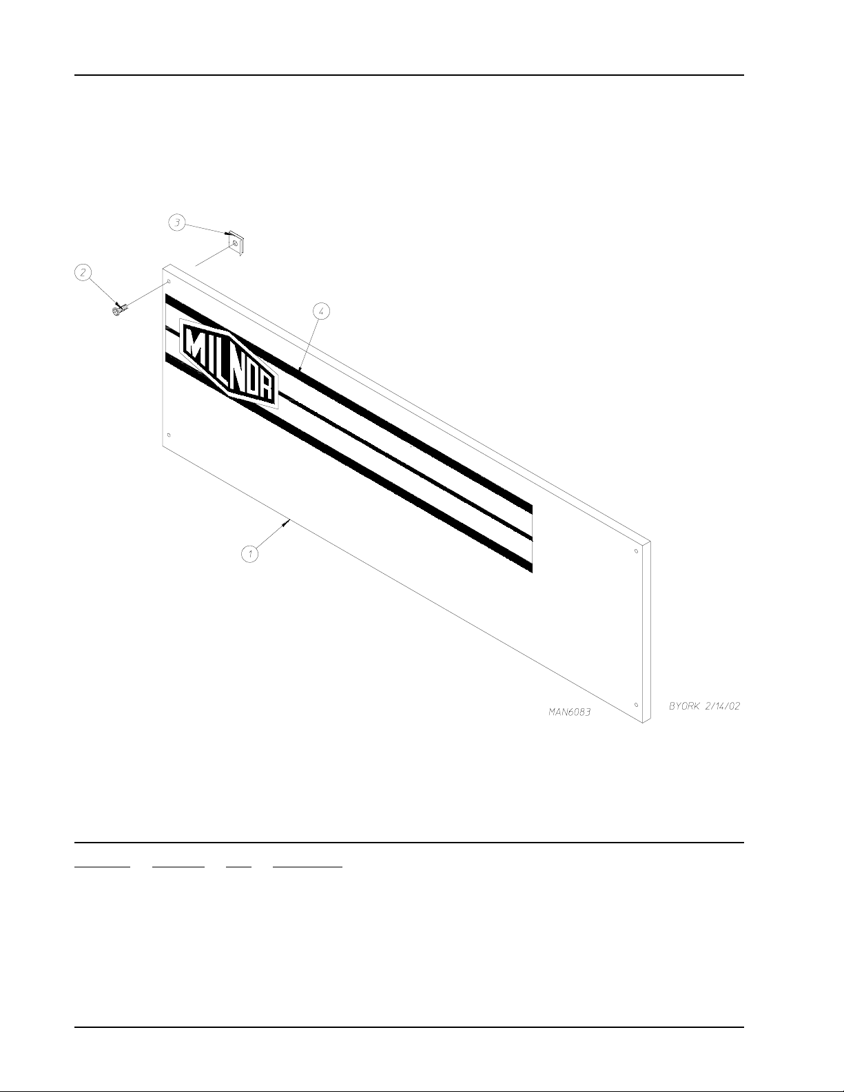
Control Door Assembly
Illus. No. Part No. Qty. Description
1* 883256 1 Phase 7 Control Door (gas)
883222 1 Phase 7 Control Door (steam)
2 150321 4 #10-32 x 1/2” Phillips Machine Screw
3 154011 4 #10-32 Multi-Thread U-Nut
4 112366 1 Milnor Logo
* Specify color when ordering.
4 American Dryer Corporation 450 574- 3
Page 5
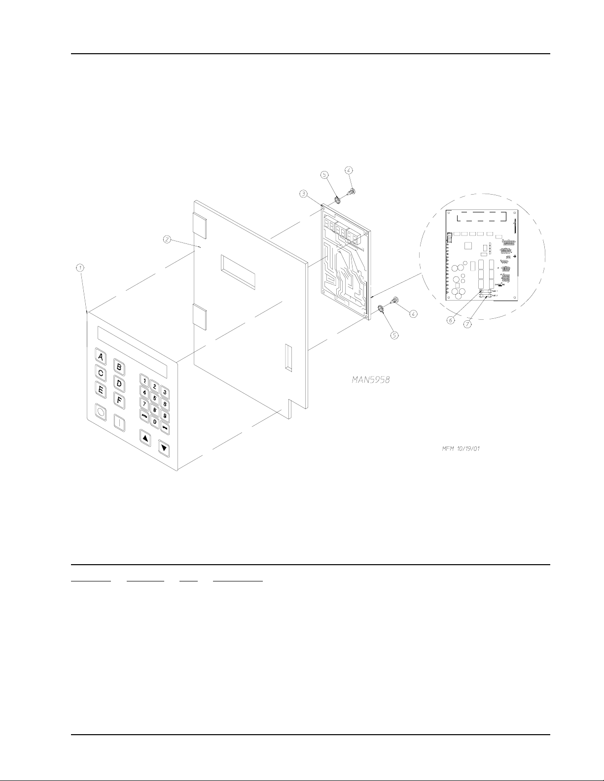
Phase 7 Non-Coin Micropr ocessor Contr ol Panel Assembly
Illus. No. Part No. Qty. Description
1 112577 1 Phase 7 Non-Coin Keyboard
2 850980 1 Phase 7 Microprocessor Controller (computer) Panel Only
3 822754 1 Phase 7 Non-Coin Reversing Microprocessor Controller (computer) Control
Panel Assembly Complete
(includes illus. nos. 1 through 7)
137243 1 Phase 7 Non-Coin Microprocessor Controller (computer) Only
4 150005 2 #6-32 x 3/4” Phillips Round Head Machine Screw
5 153010 2 #6 S tar Washer
6 136016 1 5-amp Fuse
7 136097 1 500-mA Fuse
450574-3 www.amdry.com 5
Page 6
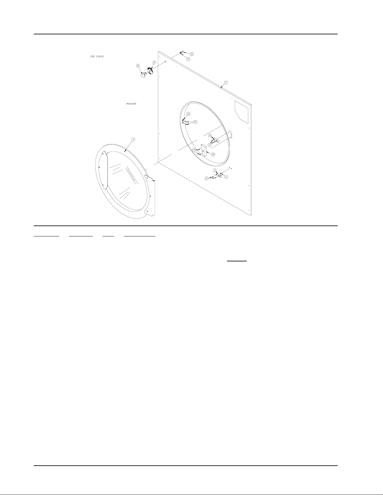
Fr ont Panel/Main Door Assemblies
(For Models Mfd. prior to September 19, 2005)
Illus. No. Part No. Qty. Description
1 835003 - Cold Rolled Steel Main Door Assembly
(Refer to Main Door Assembly on page 8)
2 150443 2 Socket Cap Screw
3 170331 1 Bottom Hinge Block
4 153031 1 Nylon Washer
5 150443 2 Socket Cap Screw
6 170329 1 Top Hinge Block
7 819026 1 Front Panel Assembly for Round Door
8 122351 1 Large “EMERGENCY STOP” (E-Stop) Mushroom Head Switch
9 122419 1 “EMERGENCY STOP” (E-Stop) Nameplate
10 801786 1 Main Door Switch and Housing for Round Door
11 150301 2 #8 x 7/16” Phillips Head TEK Screw
12 132387 1 Normally Closed Contact Block
13 132395 1 Normally Closed Contact Block with Base
14 170330 1 Friction Door Latch
(For Models Mfd. prior to September 19, 2005)
15 154215 2 5/32” Pop Rivet
(For Models Mfd. prior to September 19, 2005)
* 116260 1 8-3/8” x 56-1/8” Front Panel Left Side Insulation
* 116261 1 7-3/8” x 56-1/8” Front Panel Right Side Insulation
* 116262 1 27” x 37” Top Front Panel Insulation
* 116265 1 27” x 37” Bottom Front Panel Insulation
* 116290 1 11-1/2” x 26-1/2” Front Panel Top Center Insulation
* 116291 1 1-1/2” x 51” Hat Stiffener Insulation
* Not illustrated.
6 American Dryer Corporation 450 574- 3
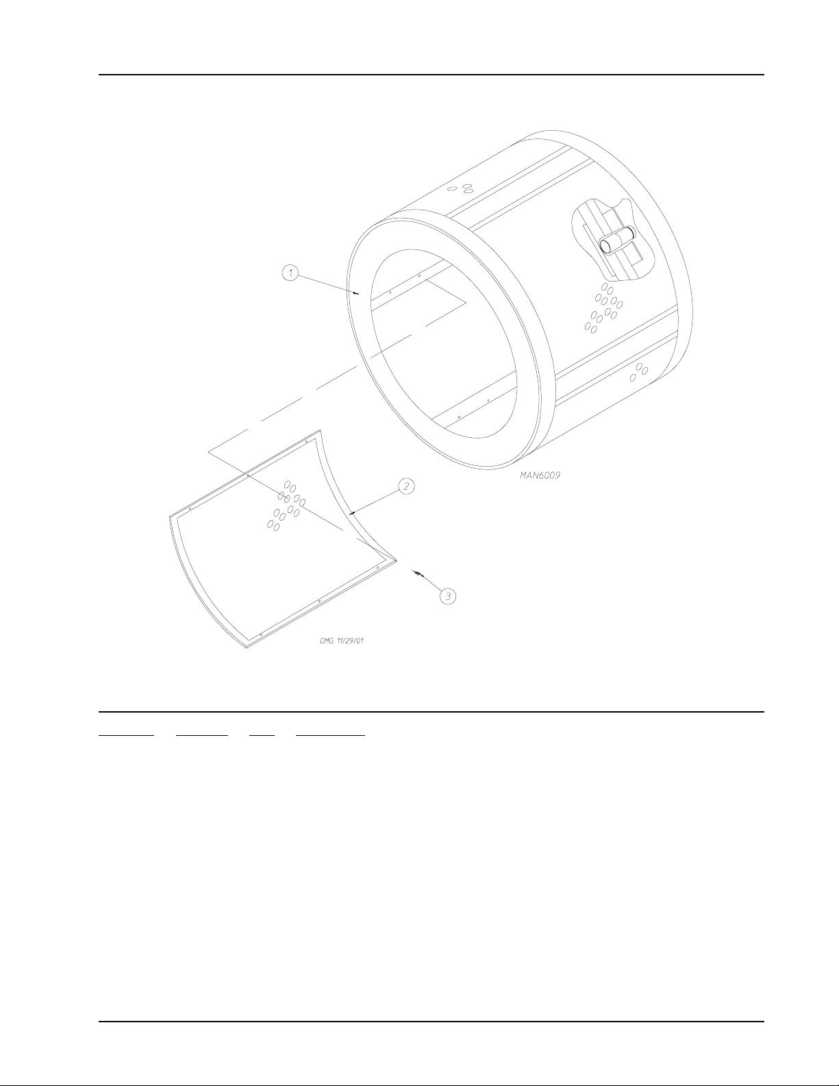
Page 7
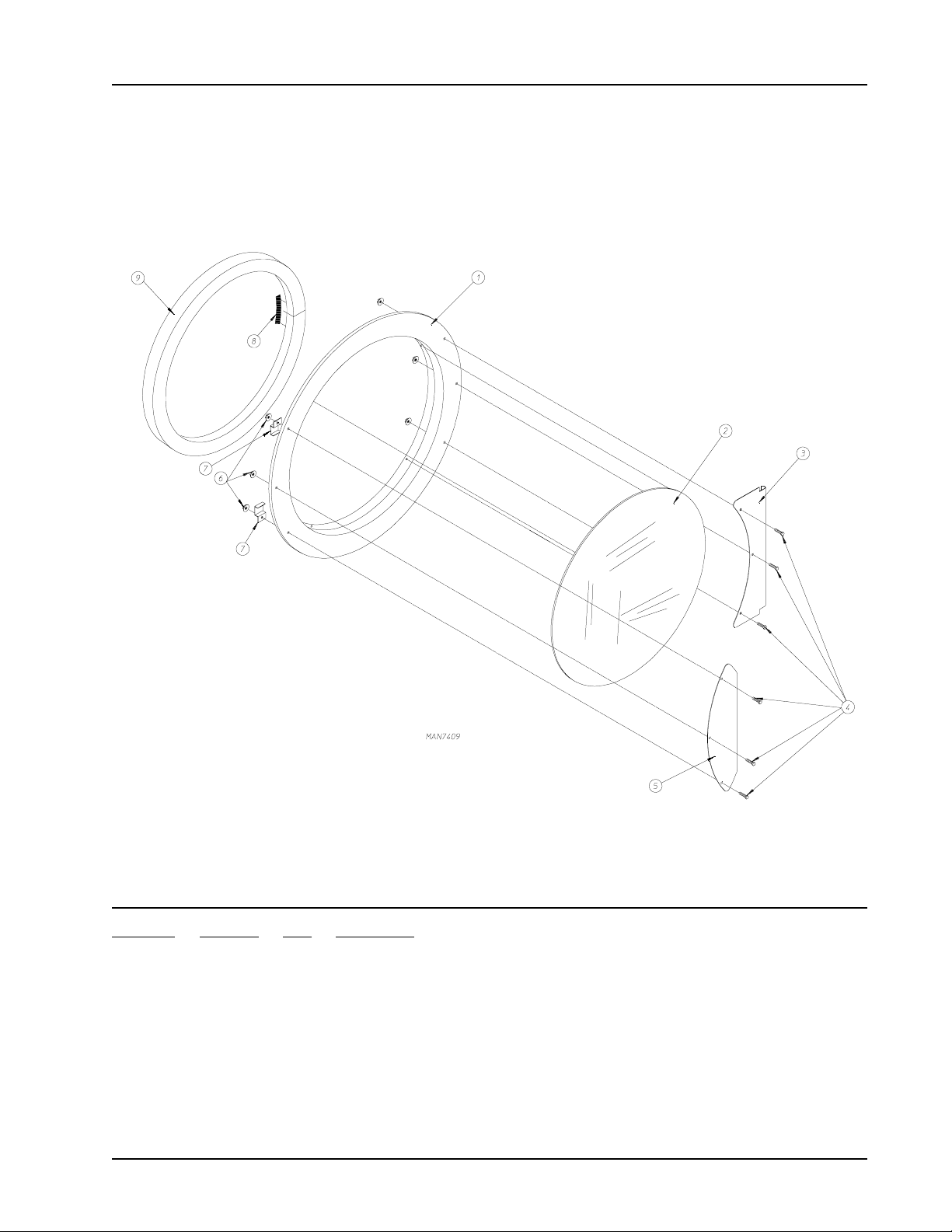
Main Door Assembly
(For Models Mfd. as of September 10, 2005)
Illus. No. Part No. Qty. Description
1 170306 1 37 1/4” Round Door Ring
2 102221 1 30” Door Glass
3 835128 1 Large Main Door Hinge Weldment
4 150683 6 1/4-20 x 5/8” Black Carriage Bolt
5 314007 1 Large Main Door Handle
6 152014 6 1/4-20 Free Spin Wash Nut
7 314007 2 37 1/4”Main Door Magnet Bracket
8 110006 2 1/2” Black Strapping Tape
9 102357 1 Extruded Steel Door Gasket
450574-3 www.amdry.com 7
Page 8
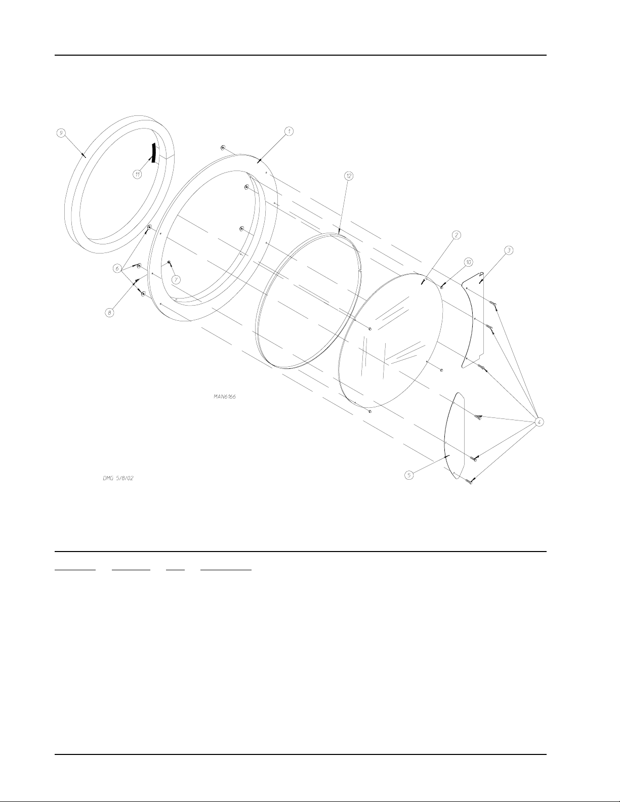
Main Door Assembly
(For Models Mfd. prior to September 10, 2005)
Illus. No. Part No. Qty. Description
1 835057 1 Large Main Door Ring
2 102214 1 30” Door Glass
3 835128 1 Large Main Door Hinge
4 150683 6 1/4-20 x 5/8” Carriage Bolt (black)
5 314729 1 Large Main Door Handle
6 152014 6 1/4-20 Free Spin Wash Nut
7 151009 1 Stainless Steel Hex Acorn Lock Nut
8 150120 1 #10-32 x 7/16” Door Latch Screw
9 102357 1 Extruded Steel Door Gasket
10 151012 4 #10-32 Nylon Acorn Nut (white)
1 1 110006 2” 1/2” Strapping Tape (black)
12 102362 8’ Gasket Tape (white)
8 American Dryer Corporation 450 574- 3
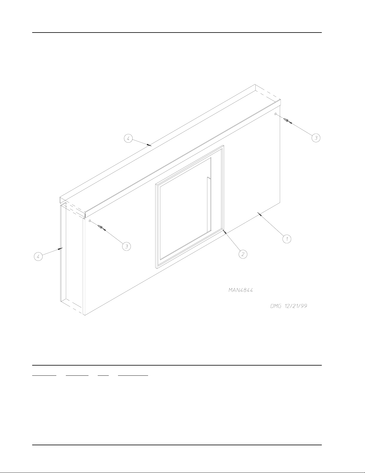
Page 9
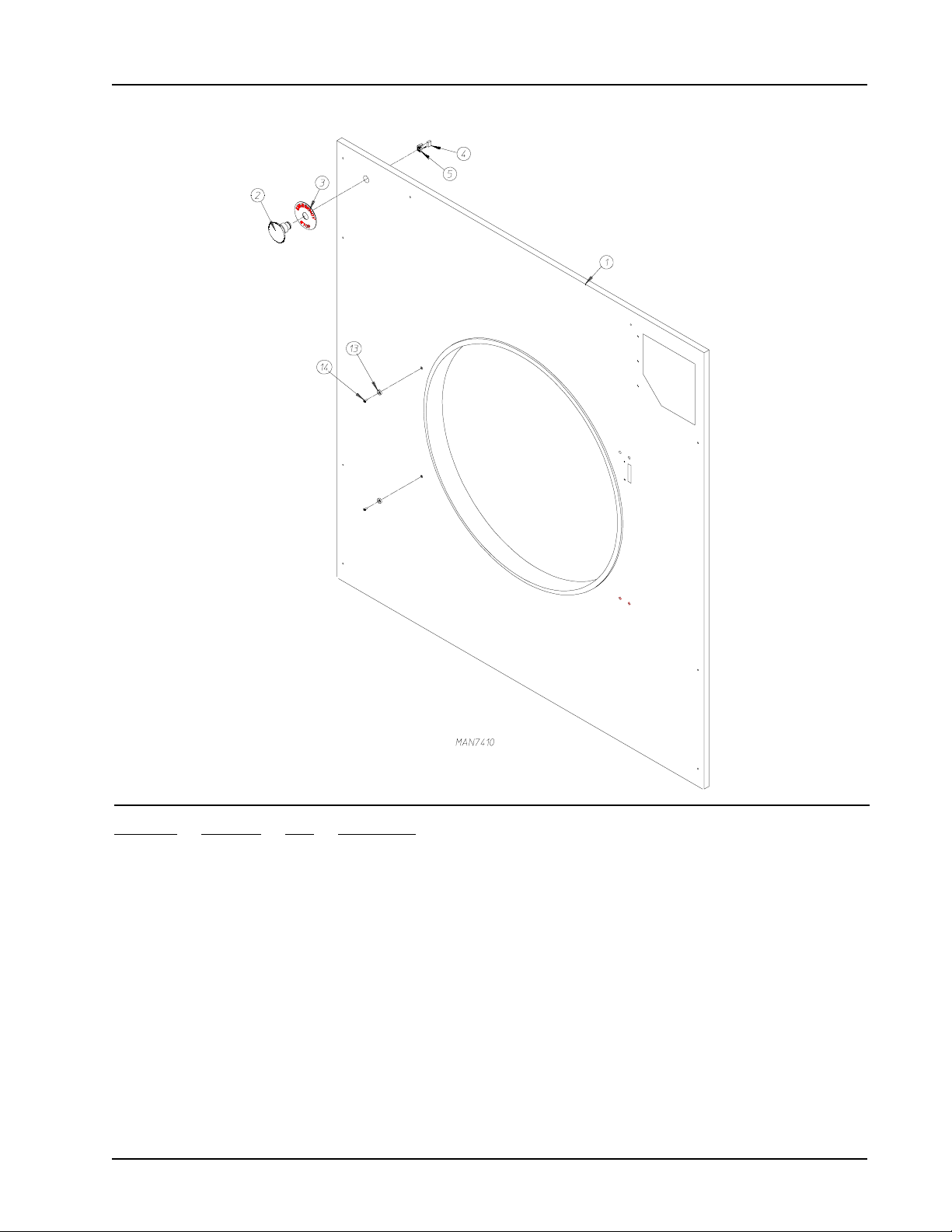
Front Panel
(For Models Mfd. as of September 10, 2005)
Illus. No. Part No. Qty. Description
1 801644 1 ML-190 Magnet Front Panel with E-Stop Weldment
2 123500 1 Large Emergency Stop Mushroom Head Switch
3 123506 1 Emergency Stop Nameplate
4 123516 1 N.O. Contact Black
5 123521 1 N.C. Contact Block w/Base
6 116337 1 18 1/2” x 36 3/4” Top Insulation
7 116338 1 20 3/4” x 36 3/4” Bottom Insulation
8 116341 1 8 3/8” x 37 3/4” Left Insulation
9 116340 1 6 3/8” x 50 1/2” Right Insulation
10 116339 1 9 x 39 1/8” Upper T op Insulation
1 1 116342 1 2 1/4” x 38 Short Stiffener Insulation
12 116343 1 2 1/4” x 50 Long Stiffener Insulation
13 102004 2 Compact Door Magnet
14 152223 2 10-32 x 1/2” FH T-20 Torx MS
450574-3 www.amdry.com 9
Page 10
Main Door Switch
Illus. No. Part No. Qty. Description
1 150006 2 #6-32 x 7/8” Phillips Pan Head Machine Screw
2 152013 2 #6-32 Hex Nut
3 153010 2 #6 S tar Washer
4 137005 1 Single-Pole Door Switch
5 150443 4 1/4-20 x 3/4” Stainless Steel Cap Screw
6 881687 1 Main Door Switch Housing Only (white)
882291 1 Main Door Switch Housing Only (coral wrinkle blue)
881702 1 Main Door Switch with Housing Assembly (white)
(includes illus. nos. 1 through 4 and 6)
882298 1 Main Door Switch Housing Assembly (coral wrinkle blue)
(includes illus. nos. 1 through 4 and 6)
7 150201 2 #10-32 x 1/4” Phillips Pan Head Screw
8 881441 1 Bottom Hinge Block (white)
882283 1 Bottom Hinge Block (coral wrinkle blue)
9 881440 1 Top Hinge Block (white)
882284 1 Top Hinge Block (coral wrinkle blue)
10 153031 1 Nylon Washer
10 American Dryer Corporation 450 574- 3
Page 11
T umbler Assembly
Illus. No. Part No. Qty. Description
1 819096 1 Tumbler Stainless Steel Assembly Complete
for models mfd. as of November 10, 2003
(includes illus. nos. 1 through 3)
819042 1 Tumbler Assembly Complete
for models mfd. prior to November 10, 2003
(includes illus. nos. 1 through 3)
2 319083 4 Perforated Tumbler Stainless Steel Panel
for models mfd. as of November 10, 2003
883328 4 Perforated Tumbler Panel
for models mfd. prior to November 10, 2003
3 150118 40 1/4-20 x 1/4” Phillips Pan Head Screw
* 881619 1 Rotational Sensor Magnet
* Not illustrated.
450574-3 www.amdry.com 11
Page 12
Lint Door Assembly
Illus. No. Part No. Qty. Description
1 882443 1 White Lint Door Assembly
(includes illus. nos. 1, 2, and 4)
882444 1 Coral Wrinkle Blue Lint Door Assembly
(includes illus. nos. 1, 2, and 4)
2 117605 5’ Neoprene Sponge Tape (sold by the foot)
3 150309 5 #10-16 x 1/2” Hex Head TEK Crimptite Screw
4 117604 9’ Neoprene Sponge Tape (sold by the foot)
12 American Dryer Corporation 450 574- 3
Page 13
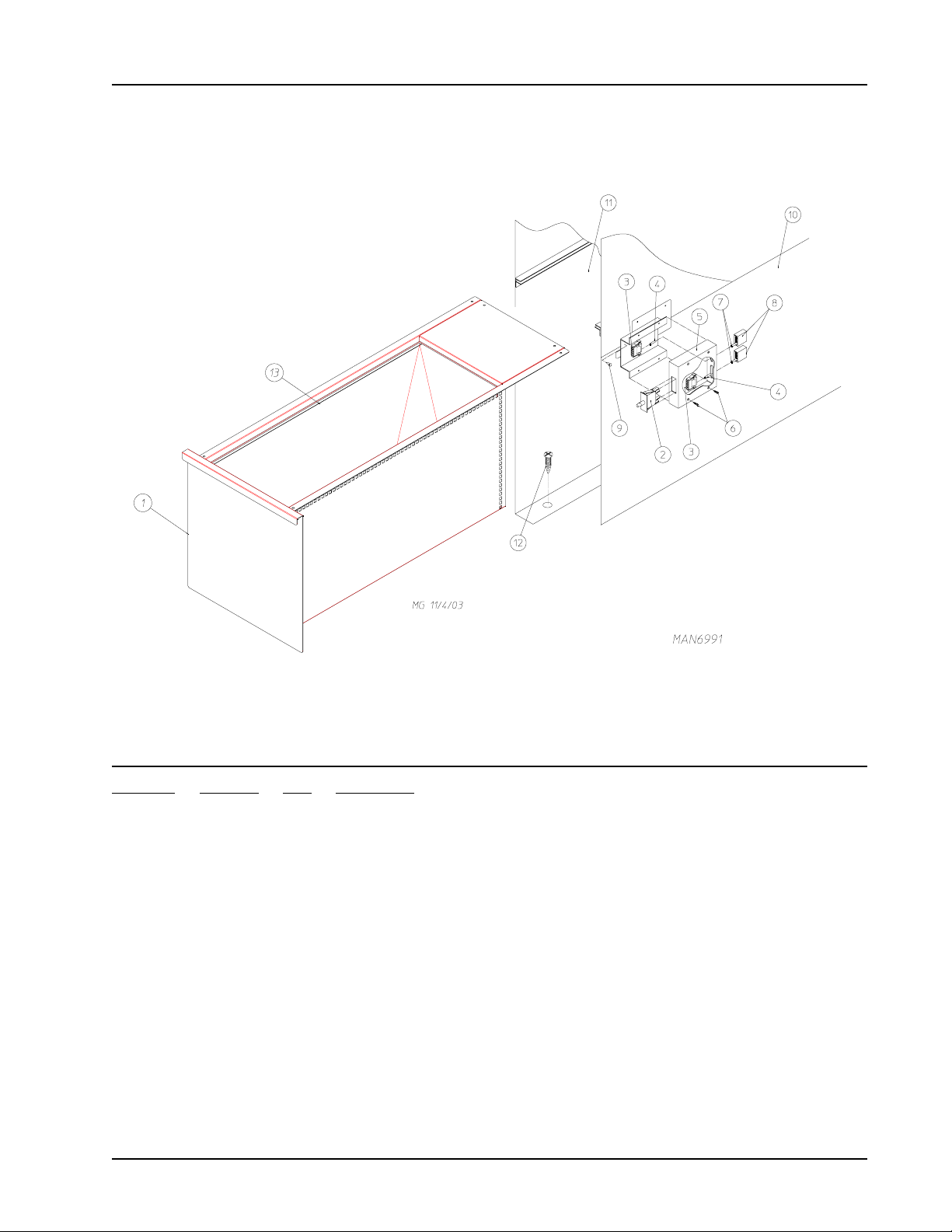
Lint Drawer/Lint Drawer Switch Box Assemblies
For Models Mfd. as of March 1, 2003
Illus. No. Part No. Qty. Description
1 884069 1 White Lint Drawer/Screen Assembly
884068 1 Coral W rinkle Blue Lint Drawer/Screen Assembly
2 122116 1 Lint Drawer Switch Only
3 122605 1 4-Pin Socket Connector
4 122701 2 Socket T erminal Only
122801 1 Pin/Socket Extraction T ool
5 882507 1 Lint Drawer Switch Box Assembly Complete
(includes illus. nos. 3 through 6)
6 150301 4 #8-18 x 7/16” Phillips Pan Head TEK Screw
7 122700 2 Pin T erminal Only
8 122604 1 4-Pin Connector
9 150301 2 #8-18 x 7/16” Phillips Pan Head TEK Screw
10 319076 1 Right Hand Divider Panel
11 319077 1 Left Hand Divider Panel
12 150301 14 #8-18 x 7/16” Phillips Pan Head TEK Screw
13 108220 1 Lint Bag
450574-3 www.amdry.com 13
Page 14

Lint Drawer/Lint Drawer Switch Box Assemblies
For Models Mfd. prior to March 1, 2003
Illus. No. Part No. Qty. Description
1 882792 1 White Lint Drawer/Screen Assembly
882793 1 Coral W rinkle Blue Lint Drawer/Screen Assembly
2 122116 1 Lint Drawer Switch Only
3 122605 1 4-Pin Socket Connector
4 122701 2 Socket T erminal Only
122801 1 Pin/Socket Extraction T ool
5 882507 1 Lint Drawer Switch Box Assembly Complete
(includes illus. nos. 3 through 6)
6 150301 4 #8-18 x 7/16” Phillips Pan Head TEK Screw
7 122700 2 Pin T erminal Only
8 122604 1 4-Pin Connector
9 150301 2 #8-18 x 7/16” Phillips Pan Head TEK Screw
10 319076 1 Right Hand Divider Panel
1 1 319077 1 Left Hand Divider Panel
12 150301 14 #8-18 x 7/16” Phillips Pan Head TEK Screw
14 American Dryer Corporation 450 574- 3
Page 15

Rotational Sensor Assembly
Illus. No. Part No. Qty. Description
1 819064 1 Tumbler Shaft Support Assembly Complete
(includes illus. nos. 1 through 8)
835339 1 Tumbler Shaft Support Bracket
2 102394 2 Tumbler Friction Pad
3 153005 6 3/8” Lock Washer
4 150619 2 3/8-16 x 1” Tap Bolt
5 153004 8 3/8” Flat Washer
6 180018 2 4” x 1-1/2” Hi-Impact Wheel
7 819046 1 Tumbler Adjustment Plate
8 819065 1 Tumbler Shoulder Screw
9 822735 1 Phase 7 Rotational Sensor Assembly
10 152005 4 3/8-16 Hex Nut
11 323433 2 Rear Wheel Shim
450574-3 www.amdry.com 15
Page 16

Idler Shaft Assembly
Illus. No. Part No. Qty. Description
1 882461 1 Idler Shaft Assembly
(includes illus. nos. 1 and 4)
2 821465 1 11” Drive Wheel
3 101227 1 1-1/2” Taper Lock Bushing
4 -------- 2 1-3/8” Pillow Block Bearing (sold only as part of illus. no. 1)
5 152011 4 1/2-13 Hex Nut
6 153026 4 1/2” Lock Washer
7 153050 4 1/2” Flat Washer
8 819015 2 Bearing Backing Plate Assembly
9 100717 1 5/16” x 5/16” x 2-3/4” Long Key
16 American Dryer Corporation 450 574- 3
Page 17

Drive Shaft Assembly
Illus. No. Part No. Qty. Description
1 882461 1 Tumbler Shaft Assembly
(includes illus. nos. 1 and 4)
2 821465 1 11” Drive Wheel
3 101227 1 1-1/2” Taper Lock Bushing
4 834308 2 1-1/2” Pillow Block Bearing
5 152011 4 1/2-13 Hex Nut
6 153026 4 1/2” Lock Washer
7 153050 4 1/2” Flat Washer
8 819015 2 Bearing Backing Plate Assembly
9 1 0115 0 1 1-1/2” Bushing with Setscrew
10 1011 89 1 2B x 8.0 Pulley
11 * 100193 2 BX-45 Cogged Belt
12 100717 1 5/16” x 5/16” x 2-3/4” Key
* Replace in matched sets (both belts).
450574-3 www.amdry.com 17
Page 18

Speed Reducer Shaft Assembly
Illus. No. Part No. Qty. Description
1 882461 1 Speed Reducing Shaft Assembly
(includes illus. nos. 1 and 4)
2 101160 1 2B x 3.4 SH Sheave
3 1 0115 0 1 1-1/2” Bushing with Setscrew
4 884308 2 1-1/2” Pillow Block Bearing
5 152011 4 1/2-13 Hex Nut
6 153026 4 1/2” Lock Washer
7 153050 4 1/2” Flat Washer
8 819015 2 Bearing Back Up Plate
9 100710 1 3/8” x 3/8” x 3” Long Key
10 101193 1 2B x 13.6” SK Sheave
11 * 100128 2 BX-50 Belt
12* 100193 2 BX-45 Cogged Belt
13 101230 1 1-1/2” Bushing with Setscrew and Key
14 -------- 1 Comes with Bushing P/N 101230
* Replace in matched sets (both belts).
18 American Dryer Corporation 450 574- 3
Page 19

Micropr ocessor T emperatur e Sensor Bracket Assembly
Illus. No. Part No. Qty. Description
1 815931 1 Microprocessor Temperature Sensor Bracket Complete
(includes illus. nos. 1 through 10)
820967 1 Microprocessor Temperature Sensor Bracket Only
2 150005 2 #6-32 x 1/4” Round Head Machine Screw
3 153010 2 #6 S tar Washer
4 130103 1 225° Auto Reset Thermostat Only
5 152000 2 #6-32 Hex Nut
6 121028 2 1/4” x .032 Insulated T erminal
7 122701 4 Socket T erminal Only
8 122605 1 4-Pin Socket Connector
9 154007 2 1/4” Push On Fastener
10 815961 1 1/4” Temperature Sensor Probe Assembly
(includes illus. nos. 6 through 10)
11 150301 4 #8-18 x 7/16” Phillips Pan Head TEK Screw
450574-3 www.amdry.com 19
Page 20

Totally Enclosed, Non-Venting Drive Motor Assembly
Illus. No. Part No. Qty. Description
1 835297 1 Motor Adjustment Plate
2 150501 4 5/16-18 x 3/4” Hex Head Tap Bolt
3 153002 8 5/16” Lock Washer
4 153001 8 5/16” Flat Washer
5 100043 1 3 hp 208-230/460v 3ø 60 Hz T otally Enclosed, Non-Venting Motor
380-416v 3ø 50 Hz T otally Enclosed, Non-Venting Motor
181019 1 3 hp 575v 3ø 60 Hz Totally Enclosed, Non-Venting Motor
6 152004 4 5/16” Hex Nut
7 101235 1 2MB35 x 1-1/8” Pulley
101132 1 5/8” Bore x 2.0” Pulley
8* 100128 2 BX-50 V-Belts
9** --------- 1 5/16” Key
10 150619 2 3/8-16 x 3” Tap Bolt
1 1 152005 4 3/8-16 Hex Nut
* Replace in matched sets (both belts).
** Consult factory.
20 American Dryer Corporation 450 574- 3
Page 21

Blower Motor Mount Assembly
Illus. No. Part No. Qty. Description
1 181030* 1 7-1/2 hp 208-230/460v 3ø 60 Hz Motor Only
181039 1 7-1/2 hp 575v 3ø 60 Hz Motor
2 1 0 1147 1 2B x 4.8 Motor Pulley 60 Hz Only
3 1 0 1152 1 SH x 1-3/8” Bushing
4 100706 1 5/16” x 5/16” x 1-3/8” Key
5 152004 4 5/16-18 Hex Nut
6 153002 4 5/16” Lock Washer
7 153001 4 5/16” Flat Washer
8 821091 1 Motor Mount Adjustment Plate Only
9 153001 4 5/16” Flat Washer
10 153002 4 5/16” Lock Washer
11 150501 4 5/16-18 x 3/4” Hex Head Machine Bolt
12 152004 4 5/16-18 Hex Nut
13 150503 2 5/16-18 x 2” Hex Head Machine Bolt
14 332322 1 Motor Mount Adjustment Angle Only
15 153001 2 5/16” Flat Washer
16 153002 2 5/16” Lock Washer
17 150501 2 5/16-18 x 3/4” Hex Head Machine Bolt
18** 100159 2 BX-61 Cogged Belt
* Specify voltage when ordering.
** Replace in matched sets (both belts).
450574-3 www.amdry.com 21
Page 22

Fan (Squirr el Cage) Shaft Mount Assembly
22 American Dryer Corporation 450 574- 3
Page 23

Fan (Squirrel Cage) Shaft Mount Assembly
Illus. No. Part No. Qty. Description
1 100612 1 1-1/4” Bore x 15” Diameter x 6” Blower/Fan (squirrel cage)
2 821078 1 Fan Shaft Mount Assembly Complete
(includes illus. nos. 1 through 19)
821073 1 Fan Shaft Mount Only
3 117604 4 Neoprene Sponge Tape (sold by the foot)
4 152006 2 1/2-20 Left Hand Jam Nut
5 153065 1 1/2” Flat Washer
6 882930 1 Fan Shaft Assembly
(includes illus. nos. 6 through 12)
7 881061 1 1-3/8” Flange Bearing with Setscrews and Grease Fitting
8 153004 4 3/8” Flat Washer
9 153005 4 3/8” Lock Washer
10 152005 4 3/8-16 Hex Nut
11 100812 2 1-3/8” Retaining Ring
12 880879 1 1-3/8” Pillow Block Bearing Only
13 153004 2 3/8” Flat Washer
14 153005 2 3/8” Lock Washer
15 150617 2 3/8-16 x 1” Hex Head Bolt
16 101135 1 2B x 5.4 SDS Pulley (for gas models Only)
17* 100159 2 BX-61 Cogged Belt (fan shaft to blower motor)
For 60 Hz Models Only
18 100706 1 5/16” x 5/16” x 1-3/8” Key
19 101194 1 SDS x 1-3/8” Bushing Only
* Replace in matched sets (both belts).
450574-3 www.amdry.com 23
Page 24

Dir ect Spark Ignition Gas Burner Assembly
24 American Dryer Corporation 450 574- 3
Page 25

Direct Spark Ignition Gas Burner Assembly
Illus. No. Part No. Qty. Description
1 142929 1 1-1/2” to 1” Reducing Coupling
2 332117 1 Pipe Bracket
3 150309 33 #10-16 x 1/2” Hex Head TEK Crimptite Screw
4 142583 1 1” x 40” Nipple
5 882537 1 Flame-Probe Wire
6 142808 1 1” x 3” Nipple
7 142602 1 1” Union
8 152013 2 #6-32 Hex Nut
9 142507 1 1” x 90° Street Elbow
10 882451 1 Direct Spark Ignition Ignitor/Flame-Probe with High Voltage Wire
11 332487 1 Gas Pipe Bracket Straight Extended
12 140017 1 1” 2 4 VAC Redundant Gas Valve (natural gas)
140018 1 ML-190 Liquid Propane Conversion Kit for 1” Valve
13 319014 1 Adjustable Gas Pipe Bracket
14 141239 1 1” 4-Port Manifold with 2” Nipple
15* 140840 4 #1 Burner Orifice (natural gas Only)
140821 4 #28 Burner Orifice (liquid propane Only)
882222 1 ML-190 Liquid Propane Conversion Kit
16 390169 1 Direct Spark Ignition Mount Manifold Rest
17 14 1110 4 Burner Tube
18 332121 1 Burner Tube Support
19 802801 1 Sail Switch
(refer to Sail Switch Assembly on
20 332113 1 Burner Box Cover Plate
21 331290 1 Ignitor/Flame-Probe Sight Hole Disc
22 151000 2 #6-32 Pal Nut
23 130201 1 330° Manual Reset Hi-Limit Only
24 150005 2 #6-32 x 1/4” Round Head Machine Screw
25 821457 1 Burner Hi-Limit Bracket
26 128937 1 Direct Spark Ignition Module (3 tries)
27 332256 1 Large Dryer Liquid Propane Burner Baffle
(liquid propane models Only)
28 153562 2 #6-32 x 3/4” Clinch Stud
29 819066** 1 Burner Assembly Complete (natural gas Only)
819067** 1 Burner Assembly Complete (liquid propane gas Only)
820904 1 Burner Box Only
page 26)
* Consult factory for elevations over 2,000 feet.
** Orifices are not included and must be ordered separately.
450574-3 www.amdry.com 25
Page 26

Sail Switch Assembly
Illus. No. Part No. Qty. Description
1 105500 1 Sail Switch Actuator Rod
2 319202 1 Sail Switch Damper (flat)
3 154002 1 1/8” Push On Fastener
4 802800 1 Sail Switch Box with Cover and Bracket Only
802801 1 Sail Switch Box Assembly Complete
(includes illus. nos. 1 through 4 and 6 through 10)
5 150300 2 #10-16 x 1/2” Hex Washer
6 150303 2 #4 x 3/4” Pan Head “A” Machine Screw
7 122200 1 Sail Switch Only
8 802799 1 Sail Switch Box Cover and Bracket Only
9 150309 2 #10-16 x 1/2” Hex Head TEK Crimptite Screw
10 154004 1 Twin Speed Nut
26 American Dryer Corporation 450 574- 3
Page 27

Steam Damper Assembly
Illus. No. Part No. Qty. Description
1 165017 1 Steam Coil Only
2 153002 6 5/16” Lock Washer
3 152004 6 5/16-18 Hex Nut
4 152002 4 1/4-20 Hex Nut
5 153007 4 1/4” Lock Washer
6 820321 2 Steam Damper Hinge Assembly
7 820994 1 Steam Damper Assembly
(includes illus. nos. 7, 10, and 11)
8 153007 4 1/4” Lock Washer
9 152002 4 1/4-20 Hex Nut
10 115995 96 Steam Damper Gasket (sold by the inch)
11 102350 2 Steam Damper Foam (68-1/2” length)
12 151007 1 7/16-20 Stainless Steel Acorn Nut
13 100499 1 1-1/2” Bore x 3” Stroke Piston
14 100500 1 Piston Support Bracket
15 152002 4 1/4-20 Hex Nut
16 153007 4 1/4” Lock Washer
17 100472 1 1/4” x 1/8” Connector
18 143110 1 1/4” Tubing (sold by the foot)
450574-3 www.amdry.com 27
Page 28

Top Console Assembly
Illus. No. Part No. Qty. Description
1 882447 1 Top Console Assembly Only (white)
(for gas models Only)
882448 1 Top Console Assembly Only (coral wrinkle blue)
(for gas models Only)
882445 1 Top Console Assembly Only (white)
(for steam models Only)
882446 1 Top Console Assembly Only (coral wrinkle blue)
(for steam models Only)
2 114521 1 “Phase 7 Non-Coin Program Location Summary” Label
3 --------- 1 Dryer Data Label (not for resale by ADC)
4 153007 8 1/4” Lock Washer
5 152005 8 1/4-20 Hex Nut
6 8 2 1 1 0 5 1 Pneumatic Valve Assembly Only
(for gas models Only)
Refer to Pneumatic Valve Assembly on page 29
82 1 1 0 4 1 Pneumatic Valve Assembly Only
(for steam models Only)
Refer to Pneumatic Valve Assembly on page 30
7 1 21 1 04 1 2” x 4” Junction Box Only
8 1 21105 1 Junction Box Cover Only
9 150615 4 1/4-20 x 3/4” Bolt
10 153018 4 1/4” Flat Washer
1 1 332186 1 Control Door Hinge Channel
28 American Dryer Corporation 450 574- 3
Page 29

Pneumatic Valve Assembly
For Gas Models Only
Illus. No. Part No. Qty. Description
1 143250 1 1/8” M.P.T. Brass Plug
2 150002 1 #6-32 x 1” Slotted Machine Screw
3 100498 1 3-Way Micro Valve Only - 24 VAC
82 1 1 0 5 1 Pneumatic Valve Assembly Complete
(includes illus. nos. 1 through 8)
4 143149 1 1/4” Poly x 1/8” M.P.T. Elbow
5 100472 1 1/4” x 1/8” Connector
6 330987 1 Micro Valve Support Bracket Only
7 153010 1 #6 S tar Washer
8 152000 1 #6-32 Hex Nut
450574-3 www.amdry.com 29
Page 30

Pneumatic Valve Assembly
For S team Models Only
Illus. No. Part No. Qty. Description
1 100496 1 1/8” Needle Valve
2 143238 3 1/8” Close Nipple
3 100498 2 3-Way Micro Valve Only - 24 VAC
82 1 1 0 4 1 Pneumatic Valve Assembly Complete
(includes illus. nos. 1 through 10)
4 143223 1 1/8” F.P.T. Brass Tee
5 150002 2 #6-32 x 1” Slotted Machine Screw
6 330987 1 Micro Valve Support Bracket Only
7 153010 2 #6 S tar Washer
8 152000 2 #6-32 Hex Nut
9 100520 2 1/8” N.P.T. Silencer (muffler)
10 100472 2 1/4” x 1/8” Connector
30 American Dryer Corporation 450 574- 3
Page 31

Air Jet Assembly
Illus. No. Part No. Qty. Description
1 332700 1 Air Jet Tube Only
2 143287 1 1/4” x 1/8” M.P.T. Male Run Tee
3 143259 2 1/4” x 1/8” F.P .T . Bulkhead Fitting
4 143100 36 1/4” Aluminum T ube (sold by the inch)
5 821081 1 Air Jet Mounting Plate Only
(includes illus. nos. 1 through 9)
332531 1 Air Jet Mounting Plate Only
6 152002 2 1/4-20 Hex Nut
7 153007 2 1/4” Lock Washer
8 143110 5 1/4” Poly-Flo Tubing (sold by the foot)
9 143149 1 1/4” x 1/8” M.P.T. x 90° Elbow
450574-3 www.amdry.com 31
Page 32

Micr opr ocessor Reversing Contactor Mounting Panel Assembly
For Models Mfd. prior to January 25, 2006
32 American Dryer Corporation 450 574- 3
Page 33

Micropr ocessor Reversing Contactor Mounting Panel Assembly
For Models Mfd. prior to January 25, 2006
Illus. No. Part No. Qty. Description
1 132439 1 17-25-amp Blower (Impellor/Fan) Overload
2 132465 1 Reversing (Impellor/Blower/Fan) Contactor - 24 VAC
3 151001 2 #8-32 Pal Nut
4 150009 2 #6-32 x 1-1/2” Phillips Pan Head Machine Screw
5 120701 1 4-Position T erminal Block
6 132531 1 3 hp Reversing Contactor
7 822745 1 208-240 VAC Transformer Assembly
8 137015 3 Arc Suppressor
9 112068 1 3-Phase (3ø) Power Input Label
10 152004 2 5/16-18 Hex Nut
11 121502 1 1/2” W ire Standoff
12 153002 2 5/16” Lock Washer
13 136008 2 Fuse Block/Holder
14 136057 2 1/2-amp (Slo-Blo) Fuse
15 332346 1 Relay Panel
16 150301 5 #8-18 x 7/16” Phillips Pan Head TEK Screw
17 151000 2 #6-32 Pal Nut
18 120765 2 End Stop/Bracket
19 150108 2 #8-32 x 1/2” Phillips Pan Head Machine Screw
20 152002 1 1/4-20 Hex Nut
21 121010 2 L-70 Ground Lug
22 120768 7-3/4” 35 x 15mm Din Mounting Rail (sold by the inch)
23 132467 1 9-13-amp Drive Motor Overload 208-240 Volt
24 112075 1 Ground Label
25 153021 1 1/4” Lock Washer
26 153525 1 1/4-20 x 1” Self-Clinching Stud
* 822742 1 Relay Panel W iring
* 825267 1 Drive/Blower Motor Contactor W iring
* Not illustrated.
450574-3 www.amdry.com 33
Page 34

Reversing Relay Panel Assembly , For 208-240 Volts
For Models Mfd. as of January 25, 2006
34 American Dryer Corporation 450 574- 3
Page 35

Reversing Relay Panel Assembly, For 208-240 Volts
For Models Mfd. as of January 25, 2006
Illus. No Part No. Qty. Description
1 132512 1 17-25A Overload Relay
2 132502 1 32 amp Contactor
3 150539 2 #8 x 1 1/4" PH PHIL AB Zinc Screw
4 120701 1 4 Position T erminal Block
5 132513 1 Reversing Contactor w/Coil Suppression
6 822764 1 208 - 240V Transformer Assembly
7 137015 1 Arc Suppressor w/ 3" Leads
8 152004 2 5/16-18 Hex Nut
9 121502 1 1/2" Wire Standoff
10 153002 2 5/ 16 Lo c k Washer
11 136008 2 Fuse Holder
12 136057 2 1/2 amp 3AG SLO-BLO Fuse
13 322346 1 Relay Panel
14 150301 7 #8-18 x 7/16" PHIL Head TEK Screw
15 120774 2 End Stop for Din Rail
16 152002 1 1/4-20 Hex Nut
17 121010 2 L70 14-4 T erminal Lug
18 120768 8 1/2" Din Rail
19 132516 1 8-11.5A Overload
20 112075 1 Ground Label
21 153021 1 1/ 4 " Lock washer
22 153525 1 1/4-20 x 1" Self Clinching Stud
23 132449 2 Auxiliary Contact Block 2 N.O.
24 132275 1 Softstart 16A 100-240VAC Control
25 132282 1 Softstart Fan
450574-3 www.amdry.com 35
Page 36

Reversing Relay Panel Assembly , For 380-416 Volts
For Models Mfd. as of January 26, 2006
36 American Dryer Corporation 450 574- 3
Page 37

Reversing Relay Panel Assembly, For 380-416 Volts
For Models Mfd. as of January 26, 2006
Illus. No Part No. Qty. Description
1 132510 1 9-13A Overload Relay
2 132501 1 18 amp Contactor
3 150539 2 #8 x 1 1/4" PH PHIL AB Zinc Screw
4 120701 1 4 Position T erminal Block
5 132497 1 Reversing Contactor w/Coil Suppression
6 830211 1 380 - 416V Transformer Assembly
7 137015 1 Arc Suppressor w/ 3" Leads
8 152004 2 5/16-18 Hex Nut
9 121502 1 1/2" Wire Standoff
10 153002 2 5/ 16 Lo c k Washer
11 136008 1 Fuse Holder
12 136057 1 1/2 amp 3AG SLO-BLO Fuse
13 322346 1 Relay Panel
14 150301 7 #8-18 x 7/16" PHIL Head TEK Screw
15 120774 2 End Stop for Din Rail
16 152002 1 1/4-20 Hex Nut
17 121010 2 L70 14-4 T erminal Lug
18 120768 8 1/2" Din Rail
19 132474 1 3.8-5.5A Overload
20 112075 1 Ground Label
21 153021 1 1/ 4 " Lock washer
22 153525 1 1/4-20 x 1" Self Clinching Stud
23 132449 2 Auxiliary Contact Block 2 N.O.
24 132275 1 Softstart 9A 100-240VAC Control
25 132282 1 Softstart Fan
450574-3 www.amdry.com 37
Page 38

Reversing Relay Panel Assembly , For 460-480 Volts
For Models Mfd. as of February 1, 2006
38 American Dryer Corporation 450 574- 3
Page 39

Reversing Relay Panel Assembly, For 460-480 Volts
For Models Mfd. as of February 1, 2006
Illus. No Part No. Qty. Description
1 132510 1 9-13A Overload Relay
2 132501 1 18 amp Contactor
3 150539 2 #8 x 1 1/4" PH PHIL AB Zinc Screw
4 120701 1 4 Position T erminal Block
5 132497 1 Reversing Contactor w/Coil Suppression
6 823252 1 460V T ransformer Assembly
7 152004 2 5/16-18 Hex Nut
8 121502 1 1/2" Wire Standoff
9 153002 2 5/ 16 Lo c k Washer
10 136008 1 Fuse Holder
11 136057 1 1/2 amp 3AG SLO-BLO Fuse
12 322346 1 Relay Panel
13 150301 7 #8-18 x 7/16" PHIL Head TEK Screw
14 135501 1 1 amp Double Pole Circuit Breaker
15 120774 2 End Stop for Din Rail
16 152002 1 1/4-20 Hex Nut
17 121010 2 L70 14-4 T erminal Lug
18 120768 8 1/2" Din Rail
19 132474 1 3.8-5.5A Overload
20 112075 1 Ground Label
21 153021 1 1/ 4 " Lock washer
22 153525 1 1/4-20 x 1" Self Clinching Stud
23 132449 2 Auxiliary Contact Block 2 N.O.
24 132275 1 Softstart 9A 100-240VAC Control
25 132282 1 Softstart Fan
450574-3 www.amdry.com 39
Page 40

Back Guard Assemblies
40 American Dryer Corporation 450 574- 3
Page 41

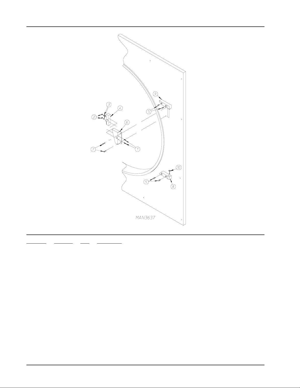
Back Guard Assemblies
Illus. No. Part No. Qty. Description
1 821956 1 20” Round Duct T ransition Piece Assembly
821793 1 20” Round Duct T ransition Piece with Damper Assembly
2 -------- 1 Wiring Diagram for Machine
3 112046 1 “Computer Ground” Label
4 114005 1 “DANGER - Hot” Label
5 112519 1 “Routine Maintenance” Label
6 112295 1 “High V oltage” Label
7 114007 1 “DANGER - High Voltage” Label
8 112014 1 “High V oltage” Label
9 114008 1 “WARNING - Fumes” Label
10 114001 1 “CAUTION - Exhaust/Lint Screen” Label
11 150512 4 1/4-20 x 1/2” Hex Head Machine Bolt
12 332309 1 Side Access Panel
13 112280 1 “Clean Lint Screen” Label
14 112017 1 “ADC Name, Address, Telephone Number” Label
15 -------- 1 Dryer Data Label (not for resale)
16 -------- 1 Wiring Diagram (supplied with dryer)
17 114521 1 “Phase 7 Program Location” Label
18 114093 1 “Important Manual Reset Hi-Limit” Label
19 170511 2 1/8” M.P.T. Zirc (grease) Fitting
20 143164 2 1/8” F .P.T . Bulkhead Fitting
21 100472 2 1/4” Tube x 1/8” M.P.T. Male Connector
22 143115 4 1/4” Nylo-Seal Tube
23 100472 2 1/4” Tube x 1/8” M.P.T. Male Connector
24 143246 2 1/4-28 x 18” F .P.T. Fitting
25 114095 1 “Do Not Dry Mop Heads” Label
26 114006 1 “WARNING - Fire Hazard” Label
27 114077 1 “Grease Instruction” Label
28 114093 1 “Important Manual Reset Hi-Limit” Label
29 153007 4 1/4-20 Lock Washer
450574-3 www.amdry.com 41
Page 42

ADC 450574 3 - 08/22/06-0
 Loading...