

Page 1
ML-122
Parts Manual
Phase 7
American Dryer Corporation
88 Currant Road
Fall River, MA 02720-4781
T elephone: (508) 678-9000 / Fax: (508) 678-9447
E-mail: techsupport@amdry.com
www .amdry.com
ADC Part No. 450570
Page 2

Retain This Manual In A Safe Place For Future Reference
American Dryer Corporation products embody advanced concepts in engineering, design, and safety. If this product is
properly maintained, it will provide many years of safe, efficient, and trouble-free operation.
ONLY qualified technicians should service this equipment.
OBSERVE ALL SAFETY PRECAUTIONS displayed on the equipment or specified in the installation manual included with
the dryer.
The following “FOR YOUR SAFETY” caution must be posted near the dryer in a prominent location.
FOR YOUR SAFETY
Do not store or use gasoline or
other flammable vapors and
liquids in the vicinity of this or
any other appliance.
W e have tried to make this manual as complete as possible and hope you will find it useful. ADC reserves the right to make
changes from time to time, without notice or obligation, in prices, specifications, colors, and material, and to change or
discontinue models.
POUR VOTRE SÉCURITÉ
Ne pas entreposer ni utiliser d’essence
ni d’autres vapeurs ou liquides
inflammables à proximité de cet
appareil ou de tout autre appareil.
Important
For your convenience, log the following information:
DATE OF PURCHASE ____________________________ MODEL NO. __________________________________________
RESELLER’S NAME _______________________________________________________________________________________
Serial Number(s) ________________________________________________________________________________________
________________________________________________________________________________________
ML-122 Phase 7
________________________________________________________________________________________
Replacement parts can be obtained from your reseller or the ADC factory. When ordering replacement parts from the factory,
you can F AX your order to ADC at (508) 678-9447 or telephone your order directly to the ADC Parts Department at (508)
678-9000. Please specify the dryer model number and serial number in addition to the description and part number, so that
your order is processed accurately and promptly.
The illustrations on the following pages may not depict your particular dryer exactly. The illustrations are a composite of the
various dryer models. Be sure to check the descriptions of the parts thoroughly before ordering.
“IMPORT ANT NOTE TO PURCHASER”
Information must be obtained from your local gas supplier on the instructions
to be followed if the user smells gas. These instructions must be posted in a
prominent location near the dryer.
Page 3

Table of Contents
Control Door Assembly ........................................................................................................................................................ 2
Phase 7 Non-Coin Microprocessor Control Panel Assembly ............................................................................................. 3
Wrapper Assembly ................................................................................................................................................................ 4
Front Panel Assembly .......................................................................................................................................................... 5
Cold Rolled Steel Door Assembly ........................................................................................................................................ 6
Main Door Switch Assembly ................................................................................................................................................ 7
Lint Drawer/Lint Screen Assembly....................................................................................................................................... 8
Microprocessor Temperature Sensor Bracket ..................................................................................................................... 9
Motorized Impellor Assembly............................................................................................................................................. 10
Tumbler Assembly................................................................................................................................................................11
Phase 7 Rotational Sensor Assembly................................................................................................................................. 12
Drive Shaft Assembly .......................................................................................................................................................... 13
Idler Shaft Assembly ........................................................................................................................................................... 14
Drive Motor Assembly ........................................................................................................................................................ 15
Direct Spark Ignition Natural Gas Burner Assembly.................................................................................................. 16, 17
Liquid Propane Gas Burner Assembly ......................................................................................................................... 18, 19
72 Kw Electric Oven Assembly........................................................................................................................................... 20
Oven Relay Box Assembly .................................................................................................................................................. 21
Steam Damper Assembly .............................................................................................................................................. 22, 23
Sail Switch Assembly .......................................................................................................................................................... 24
Pneumatic Valve Assembly ................................................................................................................................................ 25
Reversing Relay Panel Assembly, For 60 Hz, Gas and Steam Models Only
For Models Mfd. prior to March 2, 2006 .............................................................................................................. 26, 27
Reversing Relay Panel Assembly, For 50 Hz, Gas and Steam Models Only
For Models Mfd. prior to March 2, 2006 .............................................................................................................. 28, 29
Reversing Relay Panel Assembly, For 60 Hz, Electric Models Only
For Models Mfd. prior to March 2, 2006 .............................................................................................................. 30, 31
Reversing Relay Panel Assembly For 208-240V, Gas and Steam Models Only
For Models Mfd. After March 2, 2006.....................................................................................................................32, 33
Reversing Relay Panel Assembly For380-416V, Gas and Steam Models Only
For Models Mfd. After March 2, 2006................................................................................................................... 34, 35
Reversing Relay Panel Assembly For 460-480V, Gas and Steam Models Only
For Models Mfd. After March 2, 2006................................................................................................................... 36, 37
Reversing Relay Panel Assembly For 208-240V, For Electric Models Only
For Models Mfd. After March 2, 2006................................................................................................................... 38, 39
Reversing Relay Panel Assembly For 380-416V, For Electric Models Only
For Models Mfd. After March 2, 2006................................................................................................................... 40, 41
Reversing Relay Panel Assembly For 460-480V, For Electric Models Only
For Models Mfd. After March 2, 2006................................................................................................................... 42, 43
Air Jet Assembly ................................................................................................................................................................. 44
Air Jet Assembly , For Models Mfd. as of April 9, 2004...................................................................................................... 45
F.S.S. Temperature Probe Assembly ................................................................................................................................... 46
Back Draft Damper Assembly............................................................................................................................................. 47
F.S.S. Solenoid Assembly .................................................................................................................................................... 48
F.S.S. Solenoid Assembly, For Models Mfd. as of September 23, 2004.............................................................................. 49
Page 4
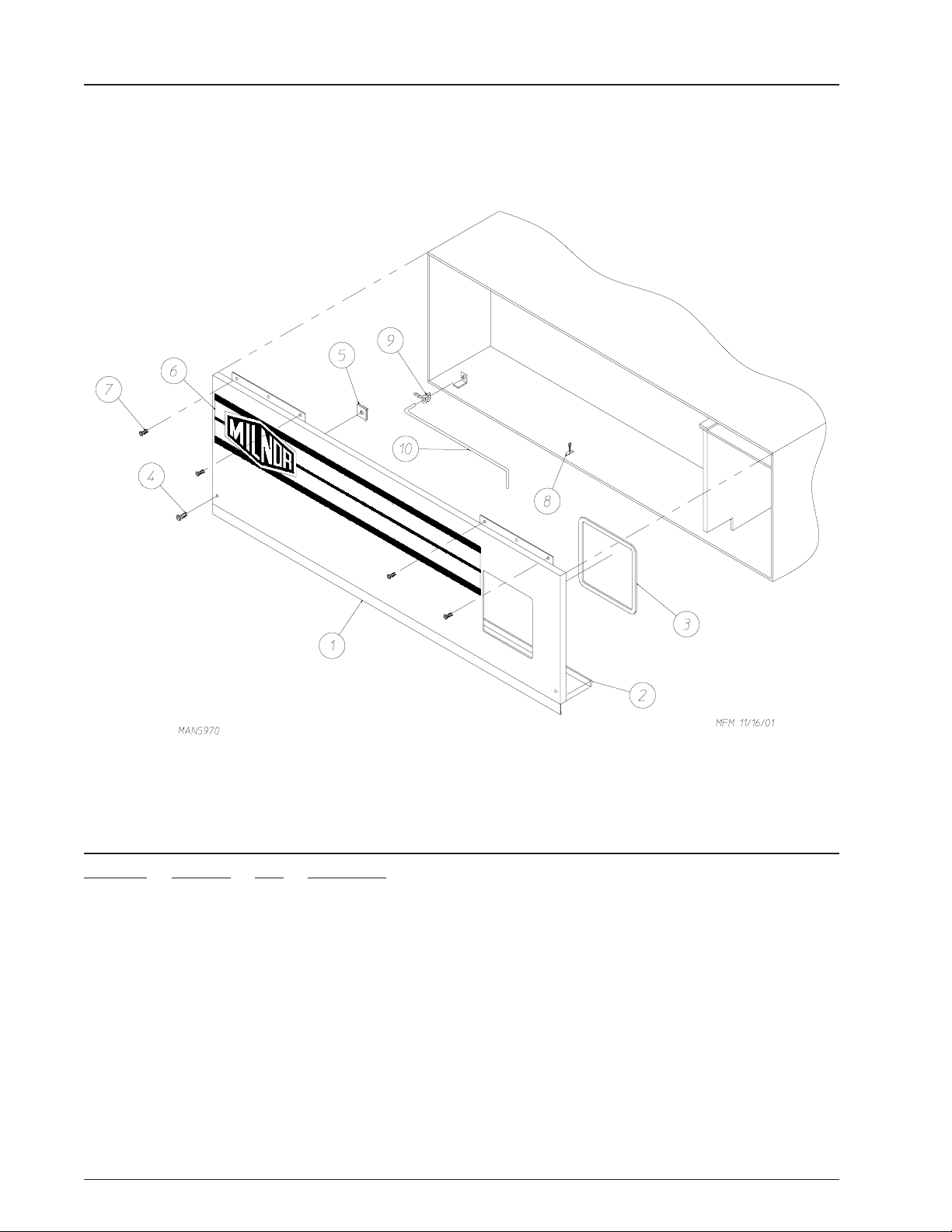
Control Door Assembly
Illus. No. Part No. Qty. Description
1 883316* 1 Control Door
(includes illus. nos. 2, 3, and 8)
2 117603 2 1/8” x 9/16” Noise Suppressor Tape
3 117604 4 Neoprene Sponge Tape (sold by the foot)
4 150314 2 #10-32 x 1/2” TORX Screw
5 154011 2 #10-32 Multi-Thread U-Nut
6 112368 1 Logo Only
7 150309 4 #10-16 x 1/2” Hex Head TEK Crimptite Screw
8 102603 1 Control Door Rod Support Catch
9 102601 1 Control Door Retainer Clip
10 102502 1 Control Door Rod
* Specify color when ordering.
2 American Dryer Corporation 450570-4
Page 5
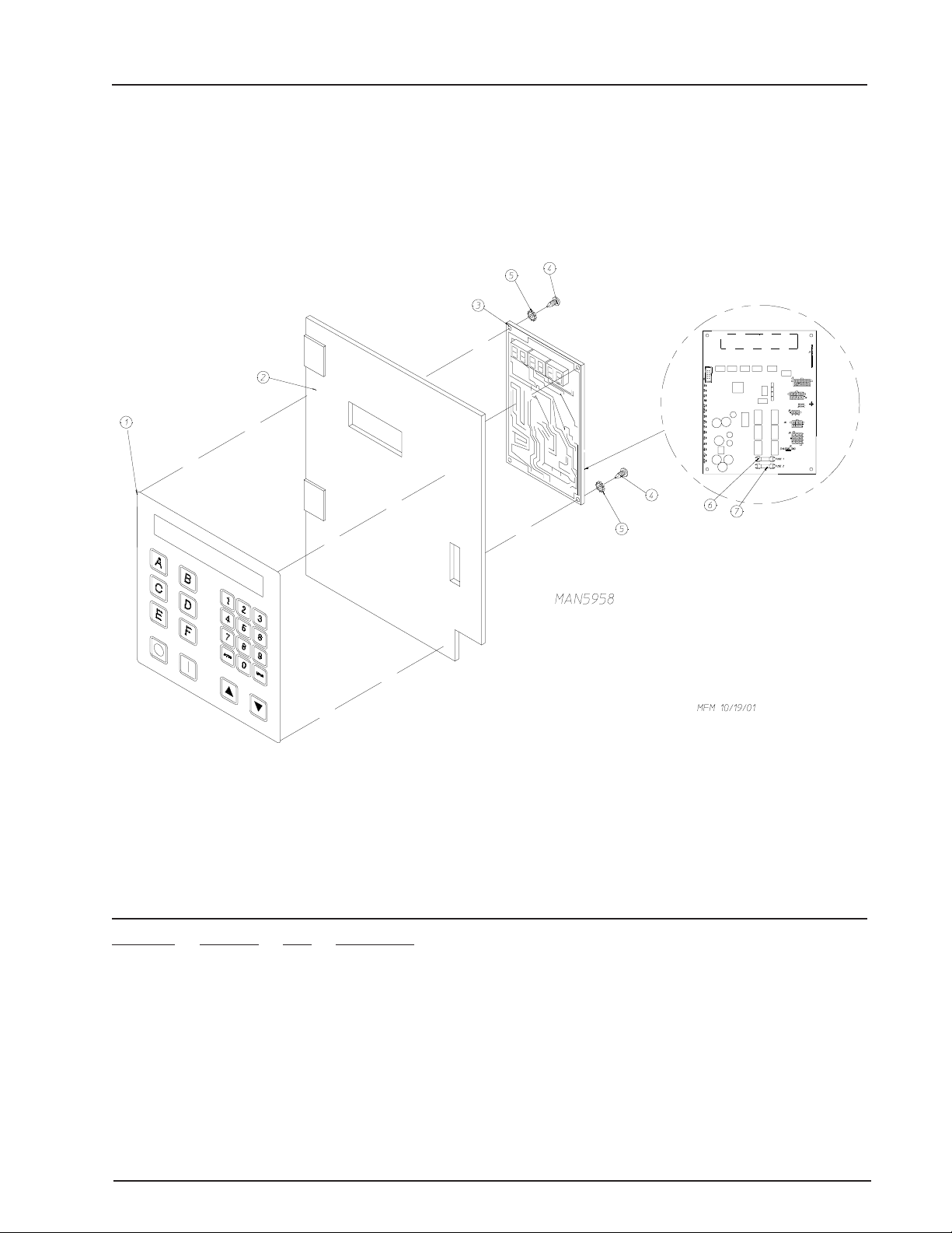
Phase 7 Non-Coin Micropr ocessor Contr ol Panel Assembly
Illus. No. Part No. Qty. Description
1 112571 1 Phase 7 Non-Coin Keyboard
2 850984 1 Phase 7 Microprocessor Controller (computer) Panel Only
3 822767 1 Phase 7 Non-Coin Reversing Microprocessor Controller (computer) Control
Panel Assembly Complete
(includes illus. nos. 1 through 7)
137247 1 Phase 7 Non-Coin Microprocessor Controller (computer) Only
4 150005 2 #6-32 x 3/4” Phillips Round Head Machine Screw
5 153010 2 #6 Star Washer
6 136016 1 5-amp Fuse
7 136097 1 500-mA Fuse
450570-4 Telephone: (508) 678-9000 / www.amdry.com 3
Page 6
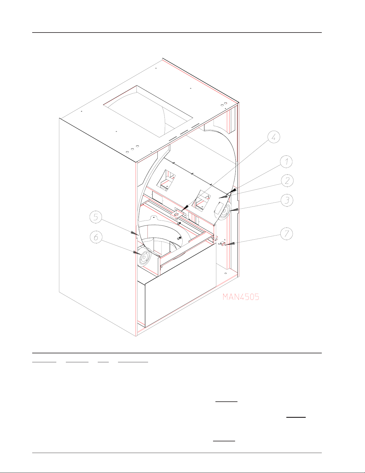
W rapper Assembly
Illus. No. Part No. Qty. Description
1 150309 20 #10-16 x 1/2” Hex Head TEK Crimptite Screw
2 859367 1 Bottom Right W rapper
3 --------- 1 Drive Shaft Assembly
(refer to Drive Shaft Assembly on page 13)
4 --------- 1 Microprocessor Temperature Sensor Bracket
(refer to Microprocessor Temperature Sensor Bracket on page 9)
5 859368 1 Bottom Left Wrapper
6 --------- 1 Idler Shaft Assembly
(refer to Idler Shaft Assembly on page 14)
7 122116 1 24 VAC Lint Door Switch
4 American Dryer Corporation 450570-4
Page 7
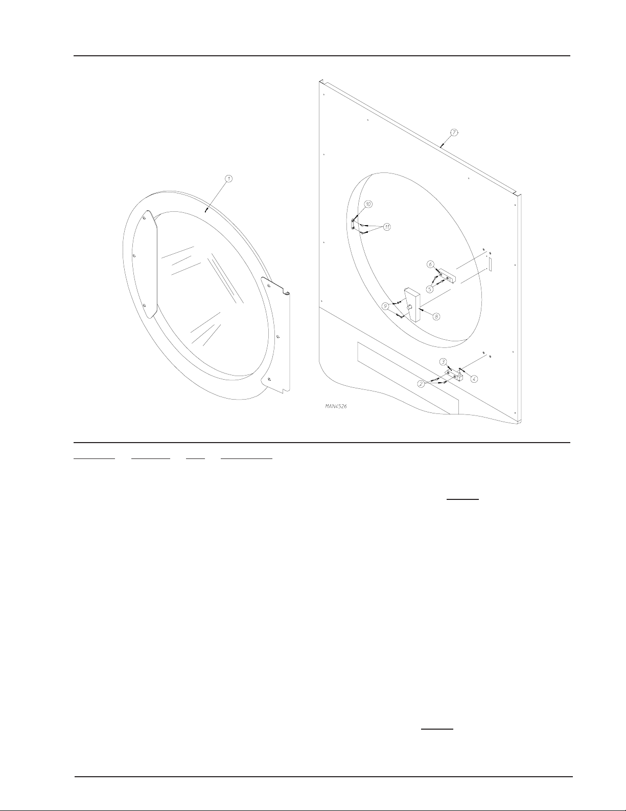
Front Panel Assembly
Illus. No. Part No. Qty. Description
1 -------- 1 Cold Rolled S teel Main Door Assembly
(refer to Cold Rolled Steel Door Assembly on page 6)
2 150443 2 Socket Cap Screw
3 881441 1 White Bottom Hinge Block
882283 1 Coral Blue Bottom Hinge Block
4 153031 1 Nylon Washer
5 150443 2 Socket Cap Screw
6 881440 1 White Top Hinge Block
882284 1 Coral Blue Top Hinge Block
7 883318 1 White Front Panel Assembly
883319 1 Coral Blue Front Panel Assembly
882288 1 White Front Panel Assembly Complete
(includes illus. nos. 2 through 11)
882289 1 Cornflower Blue Front Panel Assembly Complete
(includes illus. nos. 2 through 11)
882290 1 Coral Blue Front Panel Assembly Complete
(includes illus. nos. 2 through 11)
8 -------- 1 Main Door Switch Assembly
(refer to Main Door Switch Assembly on page 7)
9 150201 2 #10-32 x 1/4” Phillips Pan Head Tap Screw
10 170330 1 Friction Door Latch
11 154215 2 5/32 x 1/4” Rivet
450570-4 Telephone: (508) 678-9000 / www.amdry.com 5
Page 8
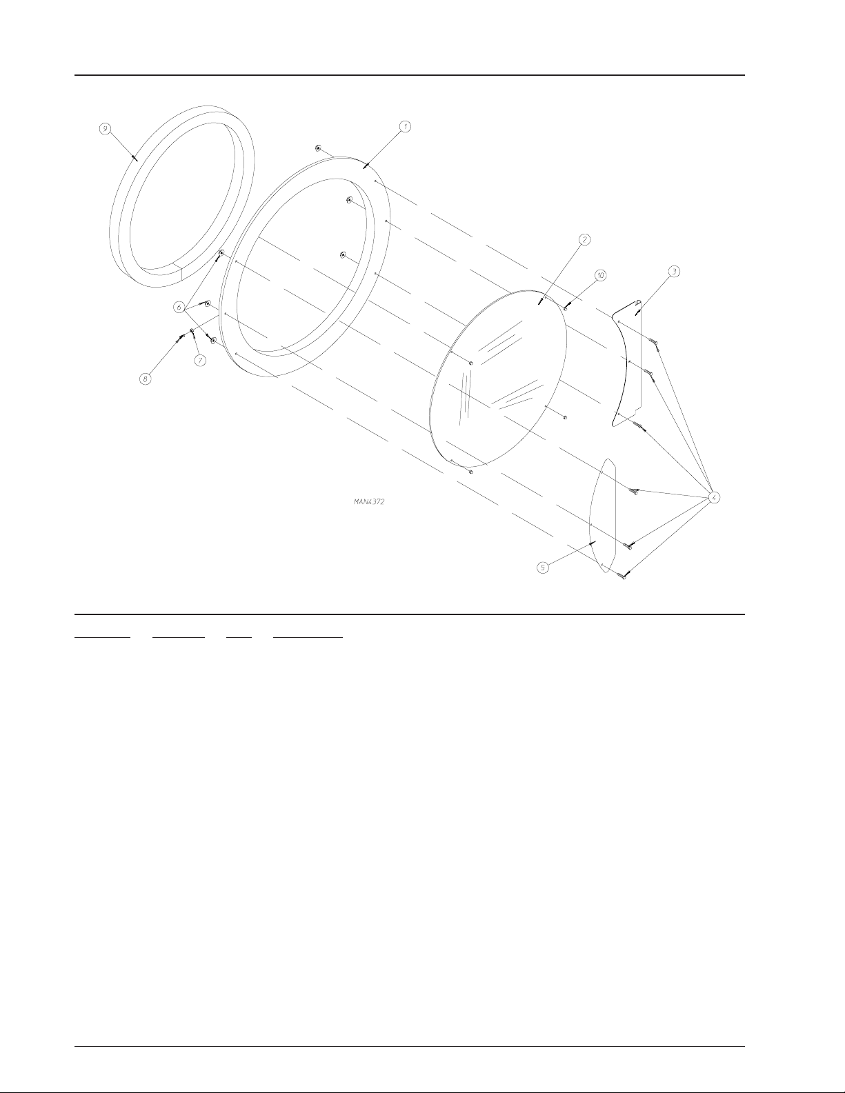
Cold Rolled Steel Door Assembly
Illus. No. Part No. Qty. Description
1 881689 1 White Cold Rolled Steel Main Door Assembly
(includes illus. nos. 2 through 10)
882292 1 Coral Blue Cold Rolled Steel Main Door Assembly
(includes illus. nos. 2 through 10)
881684 1 White Cold Rolled Steel Main Door Ring
882305 1 Coral Blue Cold Rolled Steel Main Door Ring
2 102214 1 30” Door Glass
170730 1 Door Glass Adhesive (10.3 oz. cartridge)
3 881685 1 White Main Door Hinge
882296 1 Coral Blue Main Door Hinge
4 881740 6 1/4-20 x 5/8” White Carriage Bolt
882311 6 1/4-20 x 5/8” Cornflower Blue Carriage Bolt
882294 6 1/4-20 x 5/8” Coral Blue Carriage Bolt
5 881688 1 White Main Door Handle
882295 1 Coral Blue Main Door Handle
6 881806 6 1/4-20 White Free Spin Wash Nut
882293 6 1/4-20 Coral Blue Free Spin Wash Nut
7 152008 1 #10-32 Hex Nut
8 150120 1 Door Latch Screw
9 882411 1 Door Gasket
10 151012 4 #10-32 White Nylon Acorn Nut
6 American Dryer Corporation 450570-4
Page 9
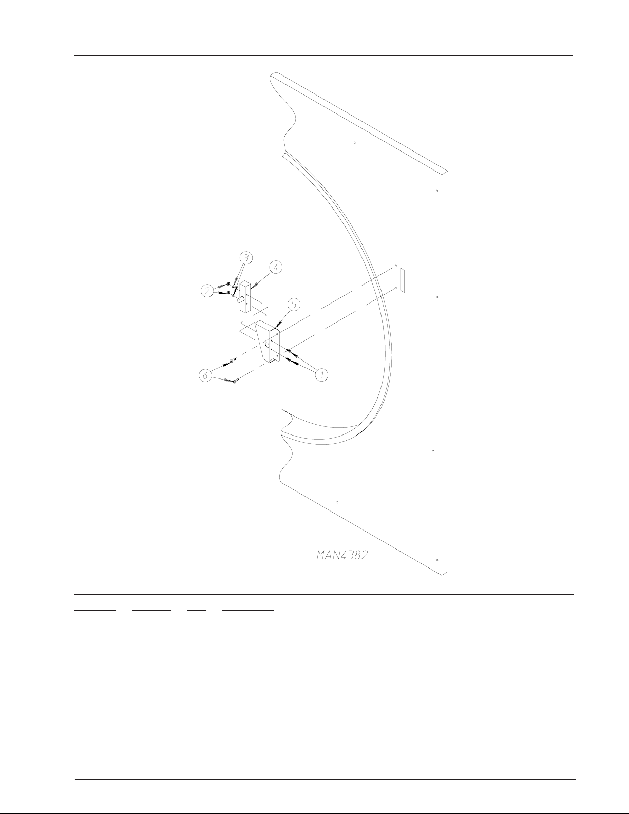
Main Door Switch Assembly
Illus. No. Part No. Qty. Description
1 150006 2 #6-32 x 7/8” Phillips Pan Head Machine Screw
2 152013 2 #6-32 Hex Nut
3 153010 2 # 6 Star Washer
4 137005 1 Door Switch
5 881702 1 White Main Door Switch Housing Assembly
(includes illus. nos. 1 through 5)
882298 1 Coral Blue Main Door Switch Housing Assembly
(includes illus. nos. 1 through 5)
881687 1 White Main Door Switch Housing Only
882291 1 Coral Blue Main Door Switch Housing Only
6 150201 2 #10-32 x 1/4” Phillips Pan Head Tap Screw
450570-4 Telephone: (508) 678-9000 / www.amdry.com 7
Page 10
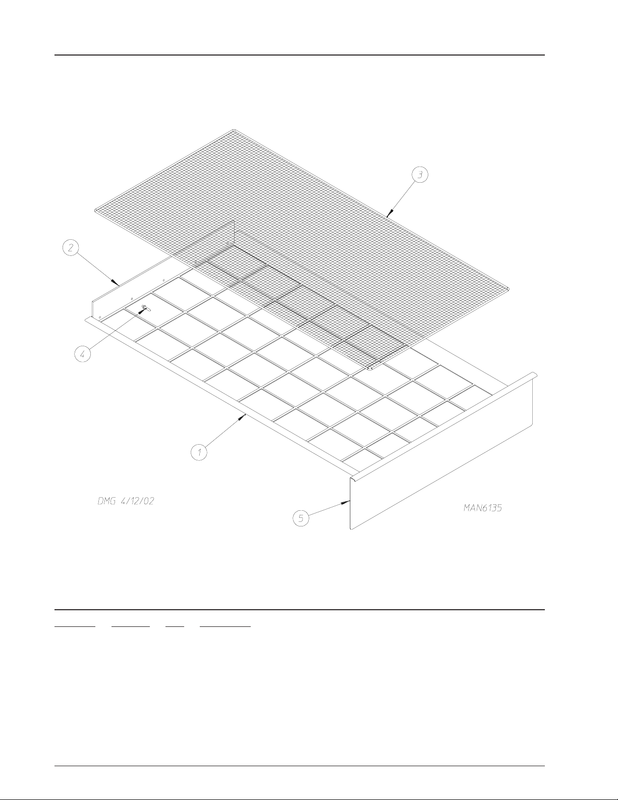
Lint Drawer/Lint Screen Assembly
Illus. No. Part No. Qty. Description
1 882299 1 White Lint Drawer Assembly
(includes illus. nos. 1 and 2)
882301 1 Coral Blue Lint Drawer Assembly
(includes illus. nos. 1 and 2)
2 115902 1 Lint Basket Felt
3 108227 1 Cloth Lint Screen Assembly
816100 1 Stainless Steel Lint Screen Assembly
4 154215 5 5/32 x 1/4” Rivet
5 117607 6’ 1/4” x 3/8” Poron Foam
8 American Dryer Corporation 450570-4
Page 11
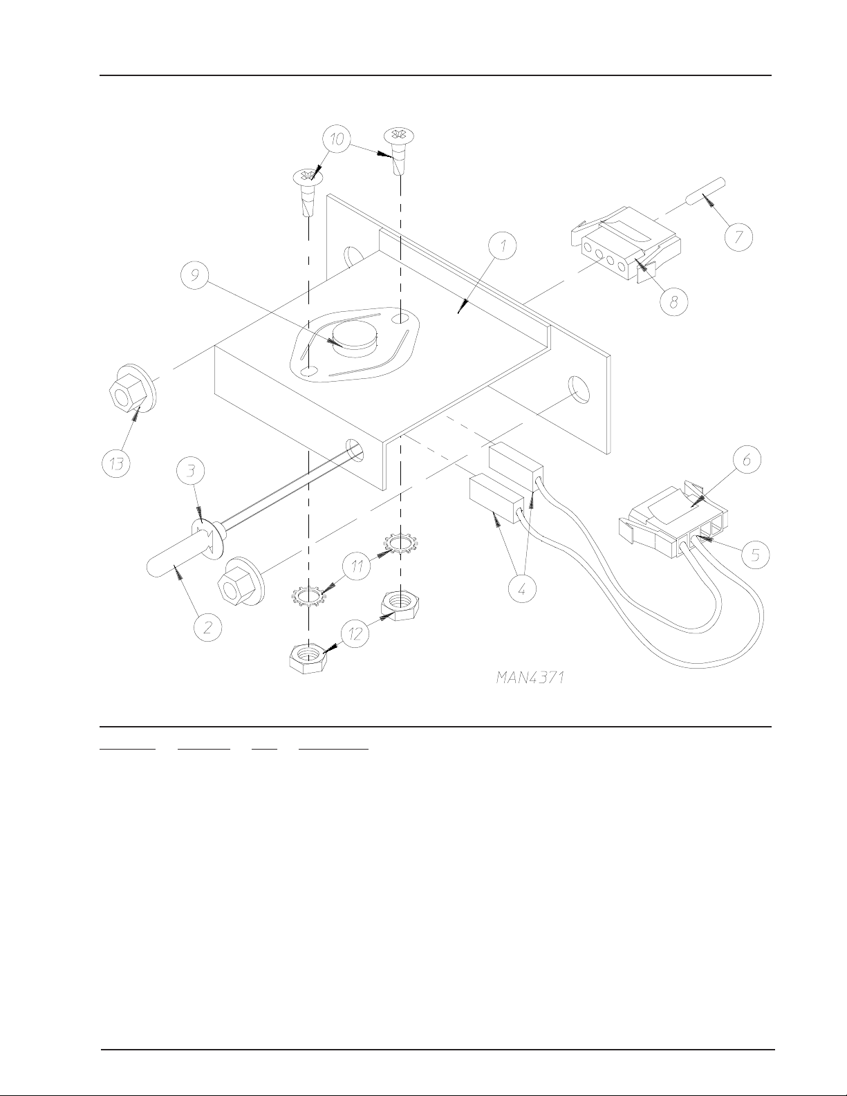
Micropr ocessor T emperatur e Sensor Bracket
Illus. No. Part No. Qty. Description
1 859372 1 Microprocessor Temperature Sensor Bracket Complete
(includes illus. nos. 1 through 13)
881089 1 Microprocessor Temperature Sensor Bracket Only
2 880252 1 4 ” Temperature Sensor
3 154007 2 1/4” Push On Fastener
4 121028 2 1/4” Terminal
5 122701 4 Socket Terminal Only
6 122605 1 4-Position Female Connector
7 122700 4 Pin Terminal Only
8 122604 1 4-Position Male Connector
9 130302 1 225º Manual Reset Thermostat
10 150005 2 #6-32 x 1/4” Phillips Round Head Machine Screw
11 153010 2 #6 Star Washer
12 152013 2 #6-32 Hex Nut
13 152014 2 1/4-20 Free Spin Wash Nut
450570-4 Telephone: (508) 678-9000 / www.amdry.com 9
Page 12
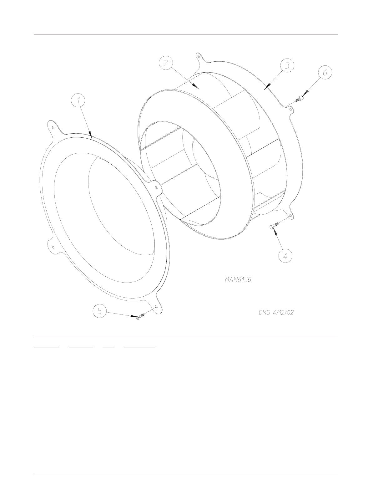
Motorized Impellor Assembly
Illus. No. Part No. Qty. Description
1 859364 1 Coop Cone
2 100622 1 Motorized Impellor (fan/blower) 230v 3ø 60 Hz
100619 1 Motorized Impellor (fan/blower) 230/400v 3ø 50 Hz, 460/480v 3ø 60 Hz
100617 1 Motorized Impellor (fan/blower) 208v 3ø 60 Hz
859361 1 Motorized Impellor Assembly 230v 3ø 60 Hz
(includes illus. nos. 1, 2, 3, and 6)
816086 1 Motorized Impellor Assembly 230/400v 3ø 50 Hz, 460/480v 3ø 60 Hz
(includes illus. nos. 1, 2, 3, and 6)
859363 1 Motorized Impellor Assembly 208v 3ø 60 Hz
(includes illus. nos. 1, 2, 3, and 6)
3 390254 1 Motor Plate
4 150504 4 5/16-18 x 1” Hex Head Bolt
5 150512 4 1/4-20 x 1/2” Hex Head Machine Bolt
6 154335 8 M10 x 16 Metric Tap Bolt
10 American Dryer Corporation 450570-4
Page 13
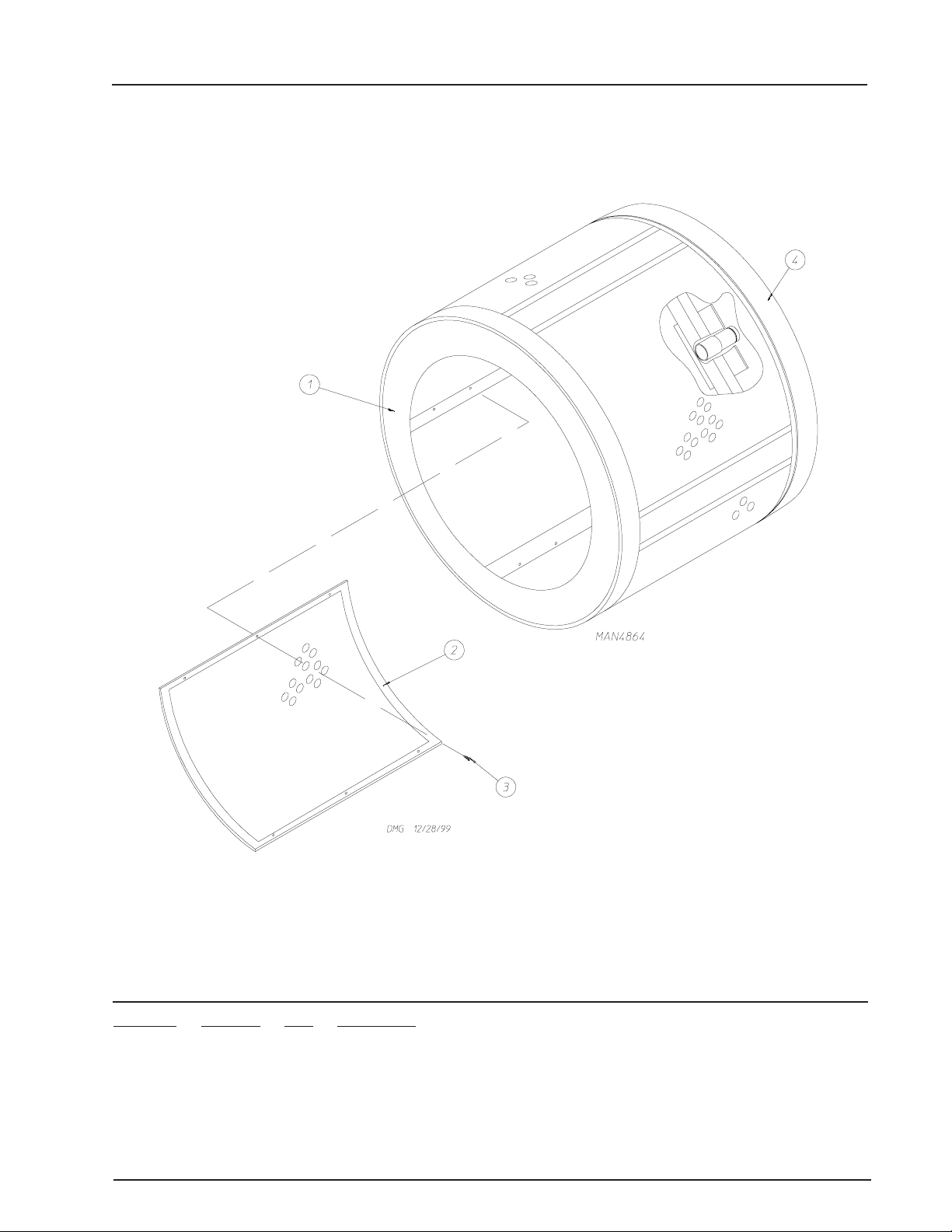
T umbler Assembly
Illus. No. Part No. Qty. Description
1 819048 1 Tumbler and Support Complete
(includes illus. nos. 1 through 3)
2 390704 4 Tumbler Side
3 150118 48 1/4-20 x 1/4” Stainless Steel Phillips Pan Head Screw
4 116006 1 Felt Collar 139-3/8” x 2-1/2” x 1/8”
-- 401010 1 3M #847 Construction Mastic
450570-4 Telephone: (508) 678-9000 / www.amdry.com 11
Page 14
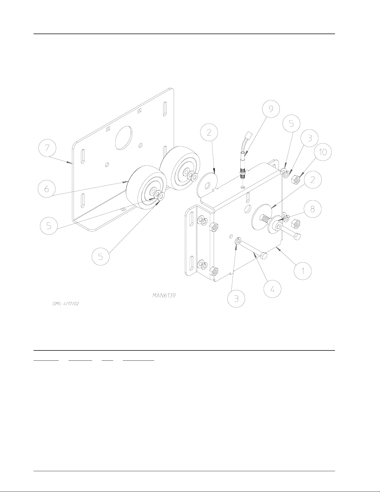
Phase 7 Rotational Sensor Assembly
Illus. No. Part No. Qty. Description
1 819064 1 Tumbler Shaft Support Assembly Complete
(includes illus. nos. 1 through 8)
835339 1 Tumbler Shaft Support Bracket
2 102394 2 Tumbler Friction Pad
3 153005 6 3/8” Lock Washer
4 150619 2 3/8-16 x 1” Tap Bolt
5 153004 8 3/8” Flat Washer
6 180018 4 4” x 1-1/2” Hi-Impact Wheel
7 819046 1 Tumbler Adjustment Plate
8 819065 1 Tumbler Shoulder Screw
9 822735 1 Phase 7 Rotational Sensor Assembly
10 152005 4 3/8-16 Hex Nut
12 American Dryer Corporation 450570-4
Page 15

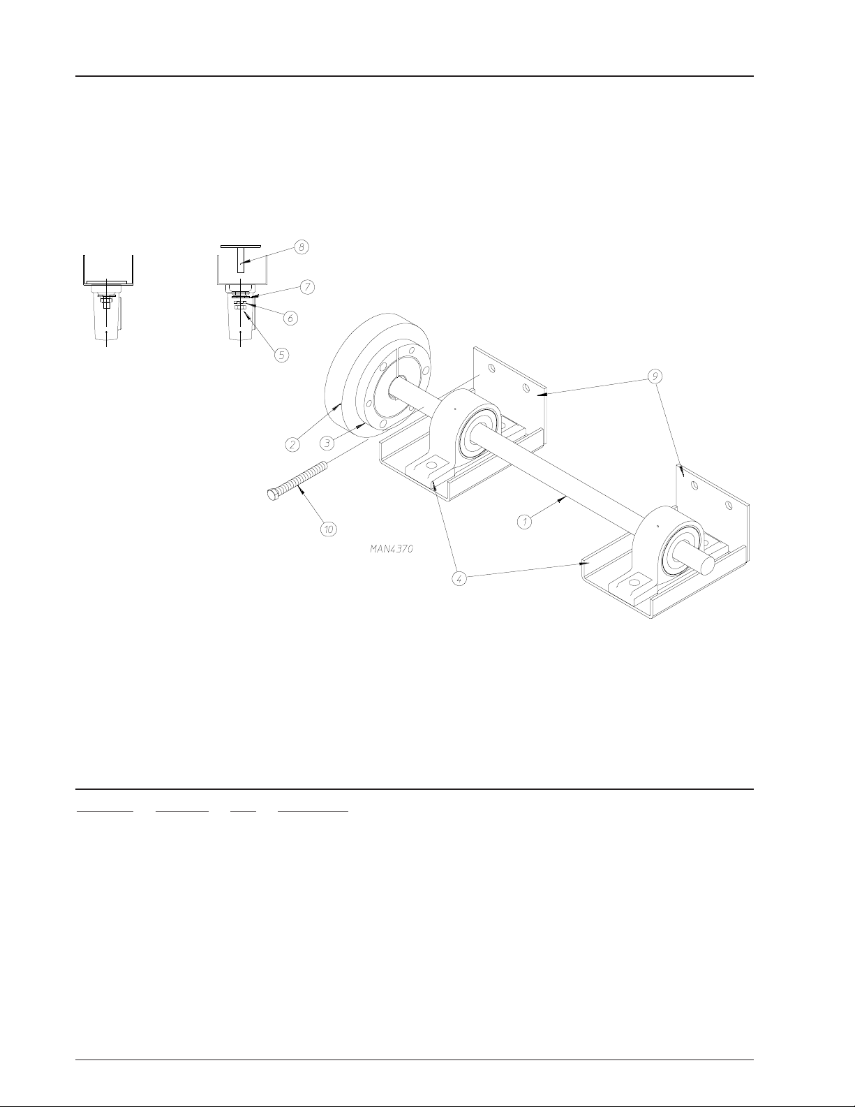
Drive Shaft Assembly
Illus. No. Part No. Qty. Description
1 390641 1 Drive Shaft Only
816061 1 Drive Shaft Assembly
(includes illus. nos. 1 through 11)
2 180033 1 6-1/4” Drive Wheel and Hub
3 180038 1 1 ” Taper Lock
4 884275 2 1” Pillow Block Bearing
5 152004 4 5/16-18 Hex Nut
6 153002 4 5/16” Lock Washer
7 153001 4 5/16” Flat Washer
8 859008 2 Bearing Bolt Plate Assembly
9 816108 2 Bearing Pad
10 150613 4 5/16-18 x 4” Tap Bolt
11 101209 1 9” Pulley
450570-4 Telephone: (508) 678-9000 / www.amdry.com 13
Page 16
Idler Shaft Assembly
Illus. No. Part No. Qty. Description
1 390642 1 Idler Shaft Only
816062 1 Idler Shaft Assembly
(includes illus. nos. 1 through 10)
2 180033 1 6-1/4” Drive Wheel and Hub
3 180038 1 1 ” Taper Lock
4 880205 2 1” Pillow Block Bearing
5 152004 4 5/16-18 Hex Nut
6 153002 4 5/16” Lock Washer
7 153001 4 5/16” Flat Washer
8 816108 2 Bearing Bolt Plate Assembly
9 859327 2 Bearing Pad
10 150613 4 5/16-18 x 4” Tap Bolt
14 American Dryer Corporation 450570-4
Page 17

Drive Motor Assembly
Illus. No. Part No. Qty. Description
1 859332 1 Motor Mount
2 152004 4 5/16” Hex Nut
3 150501 2 5/16-18 x 3/4” Hex Bolt
4 153001 3 5/16” Flat Washer
5 153002 3 5/16” Lock Washer
6 816060 1 Drive Motor Assembly (60 Hz)
(includes illus. nos. 1 through 12)
181029 1 1 hp 200-230/460v 3ø 60 Hz Drive Motor
816088 1 Drive Motor Assembly (50 Hz)
(includes illus. nos. 1 through 12)
181034 1 1 hp 200-230/460v 3ø 50 Hz Drive Motor
7 100174 1 AX53 Cogged Belt
8 101132 1 2.0 O.D. x 5/8” Machine MA Sheave 60 Hz
101130 1 2.5 x 5/8” Bore MA Sheave 50 Hz
9 150501 4 5/16-18 x 3/4” Hex Bolt
10 153002 8 5/16” Lock Washer
11 153001 8 5/16” Flat Washer
12 150501 1 5/16-18 x 3/4” Hex Bolt
450570-4 Telephone: (508) 678-9000 / www.amdry.com 15
Page 18

Dir ect Spark Ignition Natural Gas Burner Assembly
16 American Dryer Corporation 450570-4
Page 19

Direct Spark Ignition Natural Gas Burner Assembly
Illus. No. Part No. Qty. Description
1 816110 1 Burner Box Only
2 331291 2 Gas Valve Pipe Bracket
3 150309 27 #10-16 x 1/2” Hex Head TEK Crimptite Screw
4 142821 1 3/4” x 36” Nipple
5 142601 1 3/4” Union
6 142710 1 3/4” x 4” Nipple
7 142504 1 3/4” x 90° Elbow
8 142734 1 3/4” x 5-1/2” Nipple
9 142753 1 1-1/4” to 3/4” Reducing Coupling
10 354030 1 Pipe Bracket (flat)
11 140026 1 Direct Spark Ignition 3/4” 24 VAC Redundant Gas Valve (natural gas)
12 821457 1 Hi-Limit Bracket
13 141219 1 3-Port Manifold
14 140839 3 #2 Burner Orifice (natural gas)
15 335031 1 Direct Spark Ignition Mount Manifold Rest
16 141 1 36 3 Uginox Burner Tube
17 390709 1 Burner Tube Support Only
18 128914 1 Ignitor/Flame-Probe Assembly
19 390708 1 Direct Spark Ignition Burner Box Cover Plate Only
20 331290 1 Ignitor/Flame-Probe Sight Hole Disc Only
21 151000 2 #6-32 Pal Nut
22 130201 1 330° Manual Reset Hi-Limit Only
23 150001 2 #6-32 x 1/2” Right Hand Machine Screw
450570-4 Telephone: (508) 678-9000 / www.amdry.com 17
Page 20

Liquid Propane Gas Burner Assembly
18 American Dryer Corporation 450570-4
Page 21

Liquid Propane Gas Burner Assembly
Illus. No. Part No. Qty. Description
1 816110 1 Burner Box Only
2 331291 1 Pipe Bracket
3 150309 2 #10-16 x 1/2” Phillips Right Hand Crimptite Screw
4 142821 1 3/4” x 36” Nipple
5 142601 1 3/4” Union
6 142710 1 3/4” x 4” Nipple
7 142504 1 3/4” x 90° Elbow
8 142734 1 3/4” x 5-1/2” Nipple
9 142753 1 1-1/4” to 3/4” Reducing Coupling
10 354030 1 Pipe Bracket (flat)
1 1 150309 2 #10-16 x 1/2” Phillips Right Hand Crimptite Screw
12 140026 1 Direct Spark Ignition 3/4” 24 VAC Redundant Gas Valve (natural gas)
140411 1 Liquid Propane Kit
13 332256 1 Liquid Propane (Burner Baffle)
14 150309 2 #10-16 x 1/2” Phillips Right Hand Crimptite Screw
15 331291 1 Gas Valve Pipe Bracket
16 141219 1 3-Port Manifold
17 140819 3 #30 Burner Orifice (liquid propane gas)
18 150309 4 #10-16 x 1/2” Phillips Right Hand Crimptite Screw
19 335031 1 Direct Spark Ignition Mount Manifold Rest
20 150309 6 #10-16 x 1/2” Phillips Right Hand Crimptite Screw
21 141 1 36 3 Uginox Burner Tube
22 150309 7 #10-16 x 1/2” Phillips Right Hand Crimptite Screw
23 390709 1 Burner Tube Support Only
24 150309 2 #10-16 x 1/2” Phillips Right Hand Crimptite Screw
25 150309 6 #10-16 x 1/2” Phillips Right Hand Crimptite Screw
26 802801 1 Sail Switch Assembly
27 390708 1 Burner Box Cover Plate Only
28 150309 1 #10-16 x 1/2” Phillips Right Hand Crimptite Screw
29 331290 1 Ignitor/Flame-Probe Sight Hole Disc Only
30 151000 2 #6-32 Pal Nut
31 130201 1 330° Manual Reset Hi-Limit Only
32 150001 2 #6-32 x 1/2” Right Hand Machine Screw
33 821457 1 Hi-Limit Bracket
34 128914 1 Ignitor/Flame-Probe Assembly
35 150309 1 #10-16 x 1/2” Phillips Right Hand Crimptite Screw
450570-4 Telephone: (508) 678-9000 / www.amdry.com 19
Page 22

72 Kw Electric Oven Assembly
Illus. No. Part No. Qty. Description
1 816103 1 Electric Oven Box Only
2 120011 18 4 Kw/240V Open Coil Element
3 150301 2 #8-18 x 7/16” Phillips Pan Head TEK Screw
4 130400 1 290° Hi-Limit Only
5 150309 4 #10-16 x 1/2” Hex Head TEK Crimptite Screw
6 319200 1 Sail Switch Box
7 154004 1 Twin Speed Nut
8 802799 1 Sail Switch Box Cover
9 122200 1 Sail Switch Only
10 150303 2 # 4 x 3/4” Pan Head “A” Machine Screw
1 1 105500 1 Sail Switch Actuator Rod
12 319202 1 Sail Switch Damper (flat)
13 154002 1 1/8” Push On Fastener
14 150309 28 #10-16 x 1/2” Hex Head TEK Crimptite Screw
15 120081 36 Internal Ceramic Insulator
16 120080 36 External Ceramic Insulator
17 152008 72 #10-32 Hex Nut
18 121011 3’ Bus Bar
19 153009 36 #10 Star Washer
20 121032 36 #8 Rocktherm Connector
21 353222 1 Pipe Bracket
22 815707 1 Hi-Limit and Sail Switch Harness
23 153007 2 1/4” Lock Washer
24 150512 2 1/4-20 x 1/2” Long Bolt
25 819961 1 Burner Cover Assembly
26 321503 1 Right Front Oven Panel
27 321502 1 Left Front Oven Panel
28 815710 1 #8 Oven Assembly Wiring
29 156001 1 Caterpillar Grommet
30 321501 1 Oven Electrical Cover
20 American Dryer Corporation 450570-4
Page 23

Oven Relay Box Assembly
Illus. No. Part No. Qty. Description
1 132004 1 Transformer
2 131358 1 T.S.P.T. 120-amp - 24 VAC Relay
3 120706 1 Power Distribution Block
4 150521 2 1/4-20 x 2” Carriage Bolt
5 150309 8 #10-16 x 1/2” Hex Head TEK Crimptite Screw
6 150301 5 #8-18 x 7/16” Phillips Pan Head TEK Screw
7 152014 2 1/4-20 Free Spin Washer Nut
8 121010 2 L-170 Terminal Lug
9 310669 1 Box Cover
10 120768 3” 35 x 15mm Din Rail
11 120765 2 Din Rail End Stop
12 135499 1 25-amp/3 Pole Circuit Breaker
-- 842552 * Oven Relay Box Miscellaneous Wiring
* Not illustrated.
450570-4 Telephone: (508) 678-9000 / www.amdry.com 21
Page 24

Steam Damper Assembly
22 American Dryer Corporation 450570-4
Page 25

Steam Damper Assembly
Illus. No. Part No. Qty. Description
1 165012 1 Steam Coil Assembly
165019 1 Steel Steam Coil Assembly (optional)
2 153002 6 5/16” Lock Washer
3 152004 6 5/16-18 Hex Nut
4 152002 4 1/4-20 Hex Nut
5 153007 4 1/4” Lock Washer
6 820321 2 Steam Damper Hinge Assembly
7 820320 1 Steam Damper Assembly
(includes illus. nos. 7, 10, and 11)
8 153007 4 1/4” Lock Washer
9 152002 4 1/4-20 Hex Nut
10 115995 84 Steam Damper Gasket (sold by the inch)
11 102350 1 Gasket (68-12” length)
12 151007 1 7/16-20 Stainless Steel Acorn Nut
13 152007 1 7/16-20 Hex Nut
14 100499 1 1-1/4” Bore x 3” Stroke Piston
15 100500 1 Piston Support Bracket
16 152002 4 1/4-20 Hex Nut
17 153007 4 1/4” Lock Washer
18 100472 1 1/4” x 1/8” Connector
19 143110 1 1/4” Tubing (sold by the foot)
20 100472 1 1/4” x 1/8” Connector
21 100496 1 1/8” Needle Valve
22 143238 1 1/8” Close Nipple
23 100498 1 3-W ay Micro Valve 24 VAC
24 150002 2 #6-32 x 1” Round Head Machine Screw
25 153010 2 #6 Star Washer
26 152000 2 #6-32 Hex Nut
27 330987 1 Micro Valve Support Bracket
28 152002 2 1/4-20 Hex Nut
29 153007 2 1/4” Lock Washer
30 100520 1 1/8” N.P.T. Silencer (muffler)
450570-4 Telephone: (508) 678-9000 / www.amdry.com 23
Page 26

Sail Switch Assembly
Illus. No. Part No. Qty. Description
1 319203 1 Sail Switch Mounting Bracket
2 319202 1 Sail Switch Damper (flat)
3 319201 1 Sail Switch Box Cover
4 319200 1 Sail Switch Box
5 154004 1 Twin Speed Nut
6 154002 1 1/8” Push On Fastener
7 150309 4 #10-16 x 1/2” Hex Head TEK Crimptite Screw
8 150303 2 # 4 x 3/4” Pan Head “A” Machine Screw
9 122200 1 Sail Switch Only
881706 1 Sail Switch Box Assembly Complete
(includes illus. nos. 1 through 10)
10 105500 1 Sail Switch Actuator Rod
24 American Dryer Corporation 450570-4
Page 27

Pneumatic Valve Assembly
Illus. No. Part No. Qty. Description
1 330987 1 Micro Valve Bracket
2 836002 1 Air Jet Solenoid
3 150111 2 1/4-20” Phillips Round Head Machine Screw
4 152014 2 1/4-20” Free Spin Wash Nut
5 151000 2 #6-32 Pal Nut
6 100472 1 1/4” x 1/8” Male Connector
7 150002 2 #6-32 x 1” Phillips Round Head Machine Screw
8 100520 1 1/8” N.P.T. Silencer (muffler)
9 143268 1 1/8” 90º Brass Straight Elbow
10 100472 1 1/4” x 1/8” Male Connector
1 1 143115 4 1/4” Poly-Flo Tubing (sold by the foot)
450570-4 Telephone: (508) 678-9000 / www.amdry.com 25
Page 28

Reversing Relay Panel Assembly
For 60 Hz Gas and S team Models Only
For Models Mfd. prior to March 2, 2006
26 American Dryer Corporation 450570-4
Page 29

Reversing Relay Panel Assembly
For 60 Hz Gas and S team Models Only
For Models Mfd. prior to March 2, 2006
Illus. No. Part No. Qty. Description
1 150008 2 #6-32 x 1-1/4” Phillips Round Head Machine Screw
2 120701 1 4-Position Terminal Block
3 323743 1 Reversing Relay Panel
820187 1 Reversing Relay Panel Assembly 208-240v
(includes illus. nos. 1 through 15)
822739 1 MLG-122 PH7 Reversing Panel Assembly 208-240v
820217 1 Reversing Relay Panel Assembly 480v
(includes illus. nos. 1 through 15)
822039 1 ML-122 PH7 Reversing Panel Assembly 460-480v
4 151000 2 #6-32 Pal Nut
5 152004 1 5/16-18 Hex Nut
6 153002 1 5/16” Lock Washer
7 121012 1 Ground Lug
8 137060 1 Arc Suppressor Board
9 137013 4 Nylon Standoff
10 136057 1 0.5-amp 3AG (Slo-Blo) Fuse
11 150301 3 #8-18 x 7/16” Phillips Round Head TEK Screw
12 136008 1 Fuse Holder
13 132496 1 9-amp 2 hp Contactor
(for models mfd. as of April 11, 2001)
14 132497 1 Reversing Contactor
15 132070 1 115/208/240-25v 87.5 va
132067 1 460-25v 57.5va
450570-4 Telephone: (508) 678-9000 / www.amdry.com 27
Page 30

Reversing Relay Panel Assembly
For 50 Hz Gas and S team Models Only
For Models Mfd. prior to March 2, 2006
28 American Dryer Corporation 450570-4
Page 31

Reversing Relay Panel Assembly
For 50 Hz Gas and S team Models Only
For Models Mfd. prior to March 2, 2006
Illus. No. Part No. Qty. Description
1 150008 2 #6-32 x 1-1/4” Phillips Round Head Machine Screw
2 120701 1 4-Position Terminal Block
3 323743 1 Reversing Relay Panel
820219 1 380-416V 3ø 50 Hz Reversing Relay Panel Assembly
(includes illus. nos. 1 through 15)
For Gas Models Only
820192 1 380-416V 3ø 50 Hz Reversing Relay Panel Assembly
(includes illus. nos. 1 through 15)
For Steam Models Only
830185 1 D-120, ML-122 PH7 Reversing Panel 380-416v 4 wire
(for models mfd. as of April 11, 2001)
4 151000 2 #6-32 Pal Nut
5 152004 1 5/16-18 Hex Nut
6 153002 1 5/16” Lock Washer
7 121012 1 Ground Lug
8 137060 1 Arc Suppressor Board
9 137013 4 Nylon Standoff
10 136057 1 0.5-amp (Slo-Blo) Fuse
11 150301 3 #8-18 x 7/16” Phillips Round Head TEK Screw
12 136008 1 Fuse Holder Only
13 132455 1 9-amp 2 hp Contactor
14 132448 1 Reversing Contactor
15 132082 1 22-/30/40-120v/24v Transformer
450570-4 Telephone: (508) 678-9000 / www.amdry.com 29
Page 32

Reversing Relay Panel Assembly
For 60 Hz Electric Models Only
For Models Mfd. prior to March 2, 2006
30 American Dryer Corporation 450570-4
Page 33

Reversing Relay Panel Assembly
For 60 Hz Electric Models Only
For Models Mfd. prior to March 2, 2006
Illus. No. Part No. Qty. Description
1 150009 2 #6-32 x 1-1/2” Phillips Pan Head Machine Screw
2 120701 1 4-Position Terminal Block
3 323743 1 Reversing Relay Panel
4 151000 2 #6-32 Pal Nut
5 152002 1 1/4-20 Hex Nut
6 153021 1 1/4” Lock Washer
7 121012 2 Ground Lug
8 135501 1 2-Pole 1-amp Circuit Breaker
9 150301 2 #8-18 x 7/16” Phillips Head TEK Screw
10 121502 3 1/2” Wire Standoff
11 132496 1 9-amp 2 hp Contactor with Coil Suppression
12 132497 1 Reversing Contactor with Coil Suppression
13 131932 1 Relay
14 152004 1 5/16-18 Hex Nut
15 153002 1 5/16” Lock Washer
16 153525 1 1/4-20 x 1” Self Clinching Stud
17 112075 1 Ground Label
* Not illustrated.
450570-4 Telephone: (508) 678-9000 / www.amdry.com 31
Page 34

Reversing Relay Panel Assembly For 208-240V
For Gas and S team Models Only
For Models Mfd. After March 2, 2006
32 American Dryer Corporation 450570-4
Page 35

Reversing Relay Panel Assembly For 208-240V
For Gas and S team Models Only
For Models Mfd. After March 2, 2006
Illus. No Part No. Qty. Description
1 150539 2 # 8 x 1 1/4" PH PHIL AB Zinc Screw
2 120701 1 4 Position Terminal Block
3 323743 1 Relay Panel
4 152002 1 1/4-20 Hex Nut
5 153021 1 1/4" Lock Washer
6 121012 2 Ground Lug
7 136057 2 .5 amp 3AG SLO-BLO Fuse
8 150301 4 #8-18 x 7/16" PHIL Head TEK Screw
9 136008 2 Fuse Holder
10 132496 1 9 amp 2HP Contactor w/Coil Suppression
11 132497 1 Reversing Contactor w/Coil Suppression
12 822764 1 208-240V AC T ransformer Assembly
13 152004 1 5/16-18 Hex Nut
14 153002 1 5 /1 6 L o ck Washer
15 153525 1 1/4-20 x 1" Self Clinching Stud
16 112075 1 Ground Label
17 121502 3 1/2" Wire Standoff
18 132449 2 Auxiliary Contact Block 2 N.O.
19 132276 1 Softstart 9A 100-240VAC Control
20 132282 1 Softstart Fan
450570-4 Telephone: (508) 678-9000 / www.amdry.com 33
Page 36

Reversing Relay Panel Assembly For 380-416V
For Gas and S team Models Only
For Models Mfd. After March 2, 2006
34 American Dryer Corporation 450570-4
Page 37

Reversing Relay Panel Assembly For 380-416V
For Gas and S team Models Only
For Models Mfd. After March 2, 2006
Illus. No Part No. Qty. Description
1 150539 2 # 8 x 1 1/4" PH PHIL AB Zinc Screw
2 120701 1 4 Position Terminal Block
3 323743 1 Relay Panel
4 152002 1 1/4-20 Hex Nut
5 153021 1 1/4" Lock Washer
6 121012 2 Ground Lug
7 136057 2 .5 amp 3AG SLO-BLO Fuse
8 150301 4 #8-18 x 7/16" PHIL Head TEK Screw
9 136008 2 Fuse Holder
10 132495 1 6 amp 2HP Contactor w/Coil Suppression
11 132497 1 Reversing Contactor w/Coil Suppression
12 830211 1 380-416VAC Transformer Assembly
13 152004 1 5/16-18 Hex Nut
14 153002 1 5 /1 6 L o ck Washer
15 153525 1 1/4-20 x 1" Self Clinching Stud
16 112075 1 Ground Label
17 121502 3 1/2" Wire Standoff
18 132449 2 Auxiliary Contact Block 2 N.O.
19 132277 1 Softstart 3A 100-240VAC Control
20 132282 1 Softstart Fan
450570-4 Telephone: (508) 678-9000 / www.amdry.com 35
Page 38

Reversing Relay Panel Assembly For 460-480V
For Gas and S team Models Only
For Models Mfd. After March 2, 2006
36 American Dryer Corporation 450570-4
Page 39

Reversing Relay Panel Assembly For 460-480V
For Gas and S team Models Only
For Models Mfd. After March 2, 2006
Illus. No Part No. Qty. Description
1 150539 2 # 8 x 1 1/4" PH PHIL AB Zinc Screw
2 120701 1 4 Position Terminal Block
3 323743 1 Relay Panel
4 136057 1 .5 Amp 3AG SLO-BLO Fuse
5 152002 1 1/4-20 Hex Nut
6 153021 1 1/4" Lock Washer
7 121012 2 Ground Lug
8 135501 2 2 Pole 1 Amp Circuit Breaker
9 150301 4 #8-18 x 7/16" PHIL Head TEK Screw
10 136008 2 Fuse Holder
11 132495 1 6 amp 2HP Contactor w/Coil Suppression
12 132497 1 Reversing Contactor w/Coil Suppression
13 823252 1 Transformer Assembly
14 152004 1 5/16-18 Hex Nut
15 153002 1 5 /1 6 L o ck Washer
16 153525 1 1/4-20 x 1" Self Clinching Stud
17 112075 1 Ground Label
18 121502 3 1/2" Wire Standoff
19 132449 2 Auxiliary Contact Block 2 N.O.
20 132277 1 Softstart 3A 100-240VAC Control
21 132282 1 Softstart Fan
450570-4 Telephone: (508) 678-9000 / www.amdry.com 37
Page 40

Reversing Relay Panel Assembly For 208-240V
For Electric Models Only
For Models Mfd. After March 2, 2006
38 American Dryer Corporation 450570-4
Page 41

Reversing Relay Panel Assembly For 208-240V
For Electric Models Only
For Models Mfd. After March 2, 2006
Illus. No Part No. Qty. Description
1 150539 2 # 8 x 1 1/4" PH PHIL AB Zinc Screw
2 120701 1 4 Position Terminal Block
3 323743 1 Relay Panel
4 152002 1 1/4-20 Hex Nut
5 153021 1 1 / 4" Lock wa s her
6 121012 2 Ground Lug
7 136008 2 Fuse Holder
8 150301 4 #8-18 x 7/16" PHIL Head TEK Screw
9 136112 2 1.5 amp 3AG SLO-BLO Fuse
10 132496 1 9 amp 2HP Contactor w/Coil Suppression
11 132497 1 Reversing Contactor w/Coil Suppression
12 131932 1 Interposing Relay
13 152004 1 5/16-18 Hex Nut
14 153002 1 5 /1 6 L o ck Washer
15 153525 1 1/4-20 x 1" Self Clinching Stud
16 112075 1 Ground Label
17 121502 3 1/2" Wire Standoff
18 132449 2 Auxiliary Contact Block 2 N.O.
19 132276 1 Softstart 9A 100-240VAC Control
20 132282 1 Softstart Fan
450570-4 Telephone: (508) 678-9000 / www.amdry.com 39
Page 42

Reversing Relay Panel Assembly For 380-416V
For Electric Models Only
For Models Mfd. After March 2, 2006
40 American Dryer Corporation 450570-4
Page 43

Reversing Relay Panel Assembly For 380-416V
For Electric Models Only
For Models Mfd. After March 2, 2006
Illus. No Part No. Qty. Description
1 150539 2 # 8 x 1 1/4" PH PHIL AB Zinc Screw
2 120701 1 4 Position Terminal Block
3 323743 1 Relay Panel
4 136057 1 .5 amp 3AG SLO-BLO Fuse
5 152002 1 1/4-20 Hex Nut
6 153021 1 1 / 4" Lock wa s her
7 121012 2 Ground Lug
8 135501 1 2 Pole 1 amp Circuit Breaker
9 150301 5 #8-18 x 7/16" PHIL Head TEK Screw
10 139008 1 Fuse Holder
11 132495 1 6 amp 2HP Contactor w/Coil Suppression
12 132497 1 Reversing Contactor w/Coil Suppression
13 131932 1 Interposing Relay
14 152004 1 5/16-18 Hex Nut
15 153002 1 5 /1 6 L o ck Washer
16 153525 1 1/4-20 x 1" Self Clinching Stud
17 112075 1 Ground Label
18 121502 3 1/2" Wire Standoff
19 132449 2 Auxiliary Contact Block 2 N.O.
20 132277 1 Softstart 3A 100-240VAC Control
21 132282 1 Softstart Fan
450570-4 Telephone: (508) 678-9000 / www.amdry.com 41
Page 44

Reversing Relay Panel Assembly For 460-480V
For Electric Models Only
For Models Mfd. After March 2, 2006
42 American Dryer Corporation 450570-4
Page 45

Reversing Relay Panel Assembly For 460-480V
For Electric Models Only
For Models Mfd. After March 2, 2006
Illus. No Part No. Qty. Description
1 150539 2 # 8 x 1 1/4" PH PHIL AB Zinc Screw
2 120701 1 4 Position Terminal Block
3 323743 1 Relay Panel
4 136057 1 .5 amp 3AG SLO-BLO Fuse
5 152002 1 1/4-20 Hex Nut
6 153021 1 1 / 4" Lock wa s her
7 121012 2 Ground Lug
8 135501 1 2 Pole 1 amp Circuit Breaker
9 150301 3 #8-18 x 7/16" PHIL Head TEK Screw
10 136008 1 Fuse Holder
11 132495 1 9 amp 2HP Contactor w/Coil Suppression
12 132497 1 Reversing Contactor w/Coil Suppression
13 823252 1 Transformer Assembly
14 152004 1 5/16-18 Hex Nut
15 153002 1 5 /1 6 L o ck Washer
16 153525 1 1/4-20 x 1" Self Clinching Stud
17 112075 1 Ground Label
18 121502 3 1/2" Wire Standoff
19 132449 2 Auxiliary Contact Block 2 N.O.
20 132277 1 Softstart 3A 100-240VAC Control
21 132282 1 Softstart Fan
450570-4 Telephone: (508) 678-9000 / www.amdry.com 43
Page 46

Air Jet Assembly
Illus. No. Part No. Qty. Description
1 882157 6 1/4” Aluminum T ubing (sold by the foot)
2 143287 2 1/4” x 1/8” M.P.T. Tee
3 143259 3 Bulkhead Fitting 1/4” x 1/8” F.P.T.
4 143115 4 1/4” Diameter Poly-Flo T ubing
5 143154 1 1/4” Poly Union
44 American Dryer Corporation 450570-4
Page 47

Air Jet Assembly
For Models Mfd. as of April, 9, 2004
Illus. No. Part No. Qty. Description
1 859401 1 Air Jet Tubing II
2*
3 143259 1 Bulkhead Fitting, 1/4” Tube x 1/8” FPT
4 143115 1 1/4” Diameter Poly-Flo T ubing
5 143154 1 1/4” Poly Union
6 143250 1 1/8” M.P.T. Brass Plug
7 330987 1 Bracket
8 143149 2 1/4” Poly x 1/8” M.P.T. 90 Elbow°
9*
10 822734 1 Airjet Solenoid
11 150002 2 6-32 x 1Phillips RH-MS-PL TD
12 151000 2 6-32 Pal Nut Plated
13 152014 2 1/4-20 W/ 3/4 Frespin Washnut
14 121300 1 Open/Closed Bushing
15 143277 1 1/4” x 1/8” M.P.T. Elbow
* Not Shown
450570-4 Telephone: (508) 678-9000 / www.amdry.com 45
Page 48

F.S.S. Temperatur e Probe Assembly
Illus. No. Part No. Qty. Description
1 822752 1 Fire Suppression System (F.S.S.) Temperature Probe Assembly
(includes illus. nos. 1 through 5)
2 154007 2 Push On Fastener
3 390390 1 Sensor Bracket Only
4 150301 2 #8-18 Phillips Pan Head TEK Screw
5 122647 1 Connector Only
122700 2 Pins
46 American Dryer Corporation 450570-4
Page 49

Back Draft Damper Assembly
Illus. No. Part No. Qty. Description
1 883281 1 Back Draft Damper Assembly
2 152014 5 1/4-20 Free Spin Wash Nut
450570-4 Telephone: (508) 678-9000 / www.amdry.com 47
Page 50

F.S.S. Solenoid Assembly
Illus. No. Part No. Qty. Description
1 165114 1 Solenoid Valve 24V AC 50/60 Hz
2 143220 2 3/8” F.P.T. Brass Tee
3 143251 1 3/8” M.P.T. Brass Plug
4 143208 2 3/8” Comp x 3/8” M.P.T. Brass Connector
5 143108 1 20” Long Stainless Steel Flexible T ubing
6 311588 1 Sprinkler Head Mounting Plate
7 143303 1 3/8” N.P.T. Brass Locknut
8 143301 1 3/8” Brass 45° Elbow
9 152001 2 #8-32 x 3/8” OD Hex Nut
10 150430 2 #10 x 1/2” Self Drilling Screw
1 1 143581 1 3 GPM 3/8” F.P.T. Spray Nozzle
12 143025 1 3/8” N.P.T. Nylon Hose Adaptor
13 824081 1 RC Network Assembly
14 143315 1 3/8” x 1/8” Bushing
15 136987 1 Pressure Switch
(for models mfd. between December 3, 2003 and September 22, 2004)
16 182579 1 3/8” Hex Nipple
(for models mfd. between December 3, 2003 and September 22, 2004)
48 American Dryer Corporation 450570-4
Page 51

F.S.S. Solenoid Assembly
For Models Mfd. as of September 23, 2004
Illus. No. Part No. Qty. Description
1 143581 1 3 GPM 3/8” F.P.T. Spray Nozzle
2 143303 1 3/8” N.P.T. Brass Locknut
3 136987 1 Pressure Switch
4 143251 1 3/8” M.P.T. Brass Plug
5 182579 1 3/8” Hex Nipple
6 143220 1 3/8” F.P.T. Brass Tee
7 143301 1 3/8” Brass 45° Elbow
8 311588 1 Sprinkler Head Mounting Plate
9 143208 2 3/8” Comp x 3/8” M.P.T. Brass Connector
10 311587 1 V alve Bracket
11 143108 1 20” Long Stainless Steel Flexible T ubing
12 154338 2 Machine Screw
13 150309 2 #10-16 x 1/2” Hex Head TEK Crimptite Screw
14 152001 2 #8-32 x 3/8” OD Hex Nut
15 142887 1 Bushing
16 143182 1 3/4” x 1/8” x 3/8” N.P.T. Brass Tee
17 165119 1 Water Inlet Valve
18 143183 1 7/16-20 x 3/8” N.P.T. Brass Adaptor
450570-4 Telephone: (508) 678-9000 / www.amdry.com 49
Page 52

ADC 450570 4-08/09/06-0
 Loading...