

Page 1

D3030
Parts Manual
Phase 7 / Coin / S.A.F.E. System
JLA Limited
Meadowcroft Lane, Halifax Road
Ripponden
West Yorkshire, England
HX6 4AJ
Telephone: 01422 822282 / Fax: 01422 824390
Part No. 450215 -2
Page 2

Retain This Manual In A Safe Place For Future Reference
This product embodies advanced concepts in engineering, design, and safety. If this product is properly maintained, it will
provide many years of safe, efficient, and trouble-free operation.
ONLY qualified technicians should service this equipment.
OBSERVE ALL SAFETY PRECAUTIONS displayed on the equipment or specified in the installation manual included with
the dryer.
The following “FOR YOUR SAFETY” caution must be posted near the dryer in a prominent location.
FOR YOUR SAFETY
Do not store or use gasoline or
other flammable vapors and
liquids in the vicinity of this or
any other appliance.
We have tried to make this manual as complete as possible and hope you will find it useful. The manufacturer
reserves the right to make changes from time to time, without notice or obligation, in prices, specifications, colors,
and material, and to change or discontinue models.
Ne pas entreposer ni utiliser d’essence
ni d’autres vapeurs ou liquides
inflammables à proximité de cet appareil
ou de tout autre appareil.
POUR VOTRE SÉCURITÉ
Important
For your convenience, log the following information:
DATE OF PURCHASE ___________________________________________________ MODEL NO. ______________
DISTRIBUTOR’S NAME ______________________________________________________________________________
Serial Number(s) ____________________________________________________________________________________
D3030
____________________________________________________________________________________________________
____________________________________________________________________________________________________
Replacement parts can be obtained from your distributor or JLA. When ordering replacement parts from the
factory, you can FAX your order to JLA at 01422 824390 or telephone your order directly to the JLA Parts Department
at 01422 822282. Please specify the dryer model number and serial number in addition to the description and part
number, so that your order is processed accurately and promptly.
The illustrations on the following pages may not depict your particular dryer exactly. The illustrations are a composite
of the various dryer models. Be sure to check the descriptions of the parts thoroughly before ordering.
“IMPORTANT NOTE TO PURCHASER”
Information must be obtained from your local gas supplier on the
instructions to be followed if the user smells gas. These
instructions must be posted in a prominent location near the dryer.
Page 3

Table of Contents
Control Door Assembly ...............................................................................................................................4
Phase 7 Coin Microprocessor Control Panel Assembly .............................................................................5
Phase 7 Coin Microprocessor Control Box Assembly ................................................................................6
Coin Vault Assembly ...................................................................................................................................7
Front Panel Assembly .................................................................................................................................8
Main Door Switch Assembly .......................................................................................................................9
Main Door Assembly .................................................................................................................................10
Tumbler / Support Assembly..................................................................................................................... 11
Drop Lint Door Assembly .......................................................................................................................... 12
Lint Trap Assembly ...................................................................................................................................13
Tumbler Bearing Assembly .......................................................................................................................14
Non-Reversing Motor Mount Assembly ....................................................................................................15
Idler Bearing Assembly ............................................................................................................................. 16
Sensor Bracket Assemblies ...................................................................................................................... 17
Direct Spark Ignition Burner Assembly .....................................................................................................18
Hot Surface Ignition Gas Burner Assembly ..............................................................................................20
Rear Electric Relay Panel Assembly ........................................................................................................22
S.A.F.E. Temperature Probe Assembly .................................................................................................... 23
S.A.F.E. Solenoid and Piping Assembly ...................................................................................................24
Outer Top / Back Guard Assemblies.........................................................................................................25
Additional Parts Available ......................................................................................................................... 26
Page 4
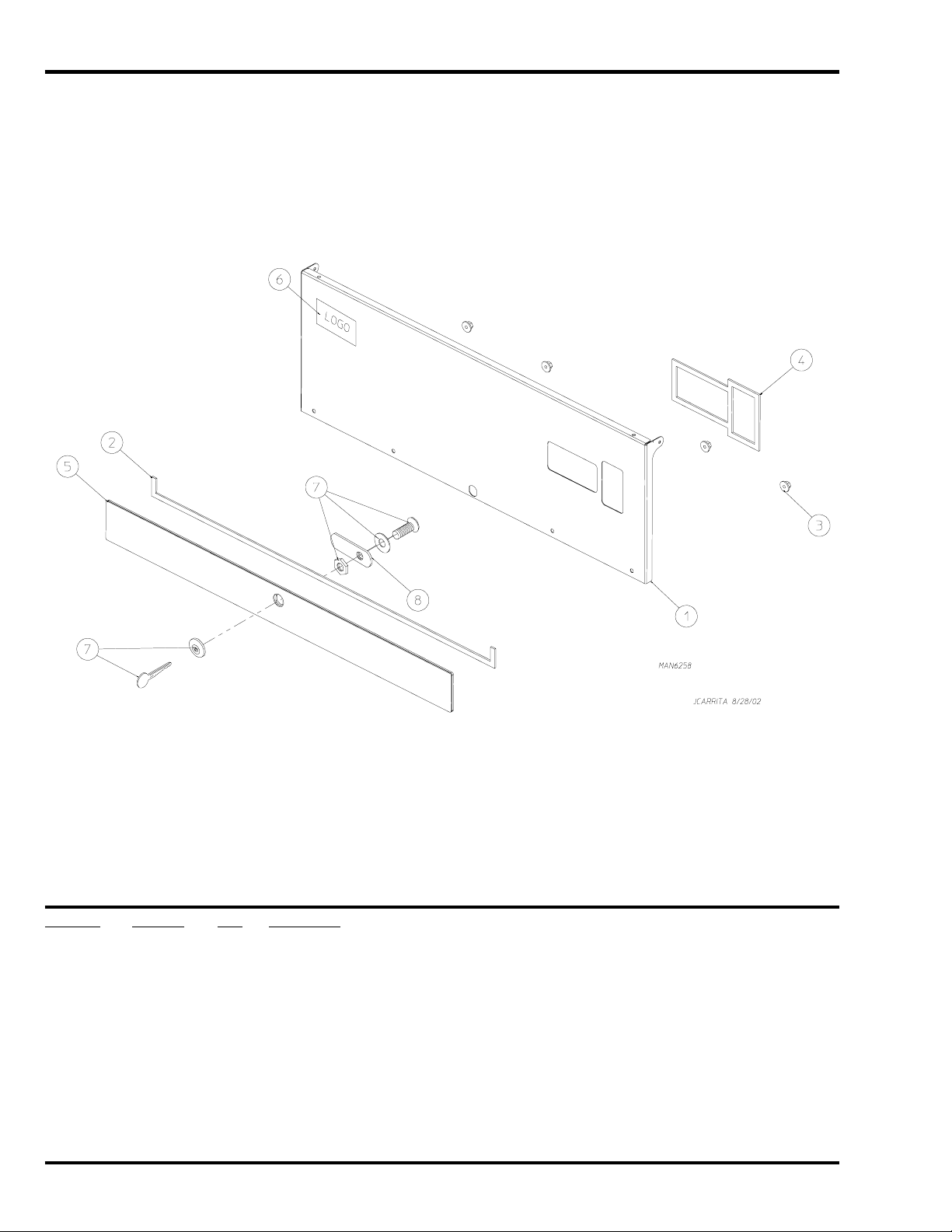
Control Door Assembly
Illus. No. Part No. Qty. Description
1 883528 1 Phase 7 Coin Control Door Assembly
(includes illus. nos. 1 through 5)
2 117604 3 Neoprene Sponge Tape (sold by the foot)
3 152014 4 1/4-20 Free Spin Wash Nut
4 117604 3 Neoprene Sponge Tape (sold by the foot)
5 883525 1 Coin Control Door Trim
6 ––––––* 1 Logo
7 160015 1 Lock with Hardware and Key
160104 1 Key ONLY
8 160032 1 Lock Cam ONLY
* Contact distributor for logo.
4 JLA Limited 450215-2
Page 5
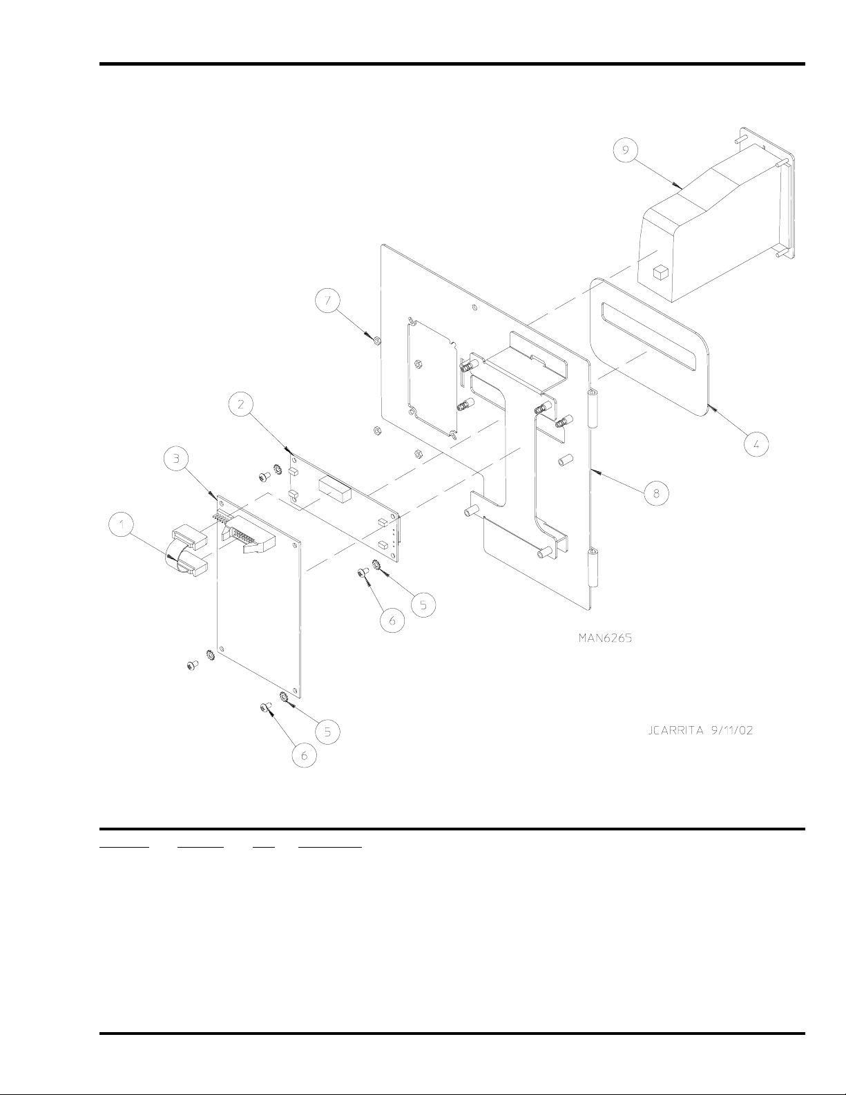
Phase 7 Coin Microprocessor Control Panel Assembly
Illus. No. Part No. Qty. Description
1 137250 1 Phase 7 Coin Ribbon Cable
2 137270 1 16” x 1” Large Character Display
3 887011 1 Phase 7 Coin Board
887012 1 Phase 7 Coin Board (with Sensor Activated Fire Extinguishing System option)
4 112575 1 Phase 7 Keypad
5 153010 4 #6 Internal and External Star Washers
6 150005 4 #6-32 x 1/4” Phillips Round Head Machine Screw
7 152102 4 M3 Metric Hex Nut
8 824363 1 Phase 7 Coin Control Panel ONLY
9 830324 1 Phase 7 Programmable Euro Coin Acceptor Assembly
450215-2 Telephone: 01422 822282 / Fax: 01422 824390 5
Page 6
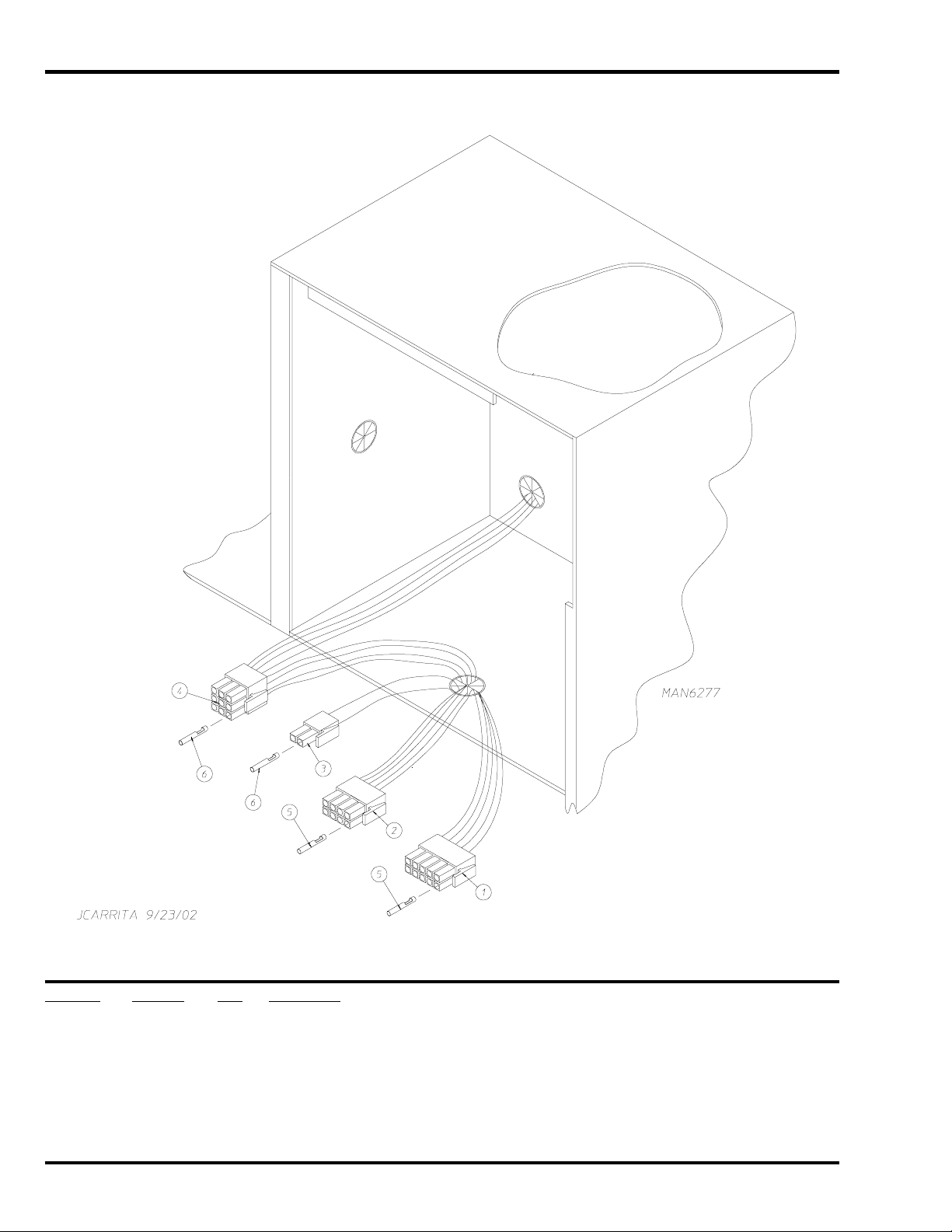
Phase 7 Coin Microprocessor Control Box Assembly
Illus. No. Part No. Qty. Description
1 122681 1 10-Pin Connector
2 122676 1 8-Pin Connector
3 122646 1 2-Pin Connector
4 122640 1 9-Pin Connector
5 122669 * Female Crimp Terminal
6 122706 * #20-16 U.M.N.L. Socket
* As needed.
6 JLA Limited 450215-2
Page 7
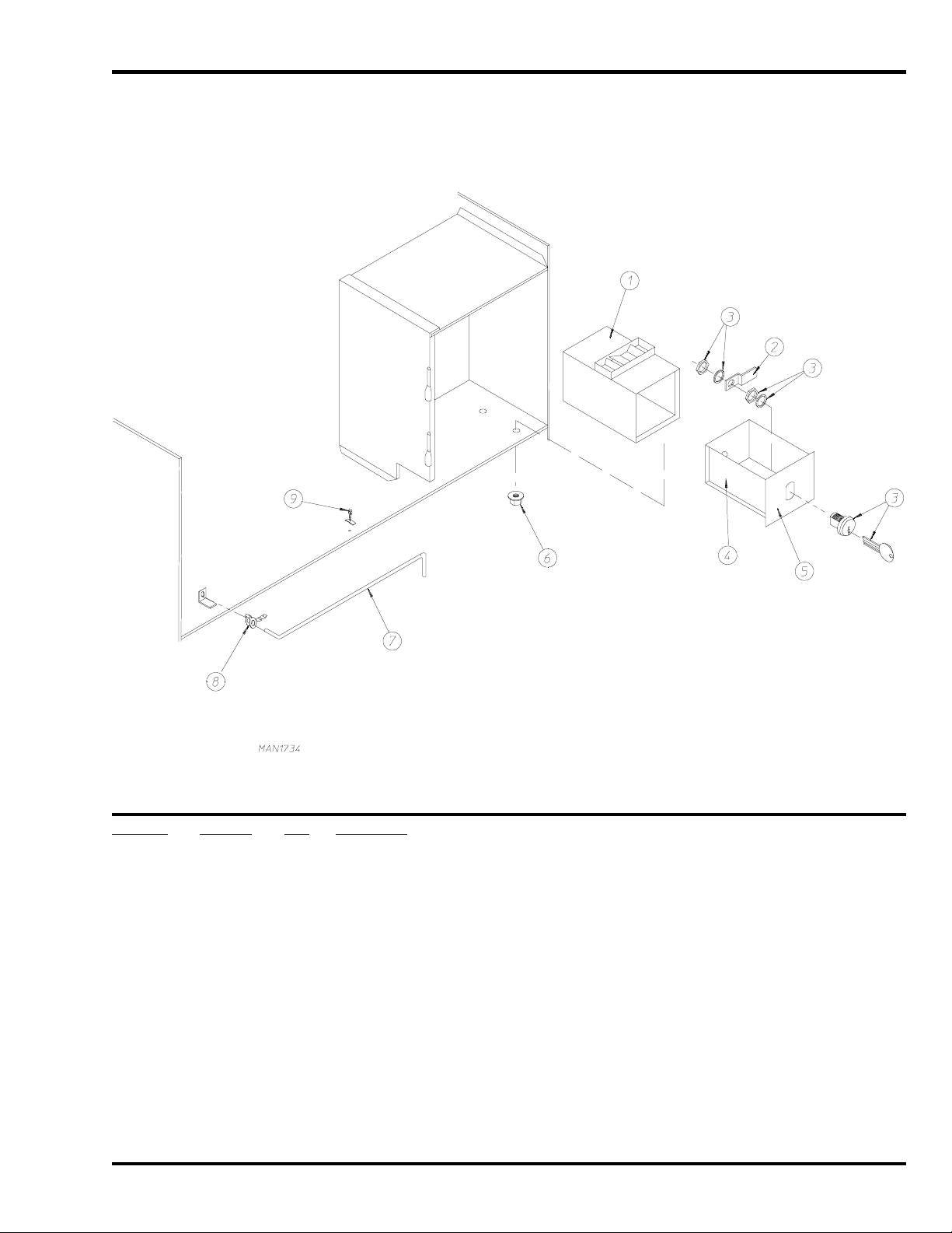
Coin Vault Assembly
Illus. No. Part No. Qty. Description
1 802112 1 Microprocessor Coin Vault Assembly Complete
(includes illus. nos. 1 through 6)
802117 1 Microprocessor Coin Vault ONLY
2 160028 1 Cam for 1/4” Turn Lock
3 875061 1 1/4” Turn Lock with Key and Cam
160105* 1 1/4” Turn Key ONLY
4 802020 1 1/4” Turn Coin Box Assembly
(includes illus. nos. 2 through 5)
802019 1 1/4” Turn Coin Box ONLY without Faceplate
125915 1 High Security (Greenwald) Coin Box ONLY with Key
5 802018 1 1/4” Turn Coin Box Faceplate ONLY
6 152014 4 1/4-20 Free Spin Wash Nut
7 102502 1 Control Door Support Rod
8 102601 1 Control Door Rod Retainer Clip
9 102603 1 Control Door Rod Catch
* Specify key number when ordering.
450215-2 Telephone: 01422 822282 / Fax: 01422 824390 7
Page 8
Front Panel Assembly
Illus. No. Part No. Qty. Description
1* 822855 1 Front Panel Assembly
(for models mfd. as of September 5, 2007)
800626 1 Front Panel Assembly
(for models mfd. prior to September 5, 2007)
(includes illus. nos. 1 through 3)
2 154215 2 1/8” Pop Rivet
(for models mfd. prior to September 5, 2007)
3 170330 1 Friction Door Latch
(for models mfd. prior to September 5, 2007)
4 150300 1 #10-16 x 1/2” Hex Washer TEK Screw
5 150301 8 #8-18 x 7/16” Phillips Pan Head TEK Screw
6 881152 1 Black Top Hinge Block Assembly
7 150445 4 1/4-20 x 7/8” Black Cap Head Setscrew
8 881151 1 Black Bottom Hinge Block Assembly
153031 1 1/4” Nylon Washer … Not Illustrated
9 102004 2 Door Magnet
(for models mfd. as of September 5, 2007)
10 152223 2 T-20 TORX
(for models mfd. as of September 5, 2007)
* Specify color when ordering.
8 JLA Limited 450215-2
®
Screw
Page 9
Main Door Switch Assembly
Illus. No. Part No. Qty. Description
1 153566 2 #6-32 x 7/8” Clinch Stud
2 152013 2 #6-32 Hex Nut
3 153010 2 #6 Star Washer
4 137005 1 Single-Pole Door Switch
5 122636 2 Flag Terminal
6 881211 1 Main Door Switch Housing
7 150301 2 #8-18 x 7/16” Phillips Pan Head TEK Screw
450215-2 Telephone: 01422 822282 / Fax: 01422 824390 9
Page 10

Main Door Assembly
Illus. No. Part No. Qty. Description
1 822661 1 Black Main Door Assembly Complete
(for models mfd. as of September 5, 2007)
(includes illus. nos. 1, 2, 8, 9, and 12 through 16)
881150 1 Black Main Door Assembly Complete
(for models mfd. prior to September 5, 2007)
(includes illus. nos. 1, 2, 8, and 9 through 15)
2 102354 1 Door Gasket
401010 1 Mastic Adhesive (5 oz. tube)
3 881152 1 Black Top Hinge Block Assembly
(includes illus. nos. 3 and 4)
4 150445 2 1/4-20 x 3/4” Black Cap Head Setscrew
5 153031 1 1/4” Nylon Washer
6 881151 1 Black Bottom Hinge Block Assembly
(includes illus. nos. 5 through 7)
7 150445 2 1/4-20 x 3/4” Black Cap Head Setscrew
8 150683 3 1/4-20 x 5/8” Black Carriage Bolt
9 152014 3 1/4-20 Free Spin Wash Nut
10 151010 1 #10-32 Black Hex Acorn Nut
(for models mfd. prior to September 5, 2007)
11 150120 1 Door Screw
(for models mfd. prior to September 5, 2007)
12 150683 3 1/4-20 x 5/8” Black Carriage Bolt
13 152014 3 1/4-20 Free Spin Wash Nut
14 881210 1 Black Main Door Handle ONLY
15 102211 1 20-7/16” Door Glass
170730 1 Adhesive (10.3 oz. cartridge)
16 319298 2 Magnet Bracket
(for models mfd. as of September 5, 2007)
10 JLA Limited 450215-2
Page 11

Tumbler / Support Assembly
Illus. No. Part No. Qty. Description
1* 817132 1 Tumbler ONLY
883530 1 Tumbler and Support Assembly
(includes illus. nos. 1 through 10)
2 150313 40 #10-16 x 1/2” TORX
150429 1 TORX
®
Screw Hand Driver
®
Crimptite Screw
3 301421 4 Tumbler Rib ONLY
4 116002 1 Felt Collar ONLY
5 100915 4 3/8-16 x 31” Tie Rod
6 153004 4 3/8” Flat Washer
7 800603 1 Tumbler Support ONLY
100724 1 Key … Not Illustrated
8 152027 4 3/8-16 Hex Nut
9 153005 4 3/8” Lock Washer
10 153004 4 3/8” Flat Washer
— 401010 1 #847 Adhesive for Felt Collar (5.0 oz. tube)
* Felt collar is not included and must be ordered separately.
450215-2 Telephone: 01422 822282 / Fax: 01422 824390 11
Page 12

Drop Lint Door Assembly
Illus. No. Part No. Qty. Description
1 160001 1 AD-100 Lock Assembly with Key (for coin models Only)
160103 1 AD-100 Key ONLY
2 160016 1 Lock Cam
3 108120 1 Chain for Drop Lint Door
4 883533 1 White Drop Lint Door Assembly
(includes illus. nos. 4 through 8)
5 152014 10 1/4-20 Hex Flange Nut
6 117604 7 Neoprene Sponge Tape (sold by the foot)
7 117603 3 Noise Suppressor Tape (sold by the foot)
8 883531 2 Black Trim / Kick Plate
9 150419 2 #6 x 1/2” Tamperproof TEK Screw
150418 1 Tamperproof Screw Hand Driver
12 JLA Limited 450215-2
Page 13

Lint Trap Assembly
Illus. No. Part No. Qty. Description
1 800408 1 Lint Trap Assembly Complete
(includes illus. nos. 1 and 3 through 5)
800409 1 Lint Trap ONLY
2 154200 7 5/32” Pop Rivet
3 304102 1 Lint Screen Holder ONLY
4 150300 3 #10-16 x 1/2” Hex Washer TEK Screw
5 800503 1 Lint Screen
6 150419 2 #6 x 1/2” Tamperproof TEK Screw
7 108120 1 Chain for Drop Lint Door (10-1/2” length)
– 150418 1 Tamperproof Screw Hand Driver
450215-2 Telephone: 01422 822282 / Fax: 01422 824390 13
Page 14

Tumbler Bearing Assembly
Illus. No. Part No. Qty. Description
1 880203 1 1-3/8” Flange Bearing
2 153005 4 3/8” Lock Washer
3 152005 4 3/8-16 Hex Nut
4 883387 1 Bearing Assembly Complete with Rotational Sensor
(includes illus. nos. 4 through 16 and 20)
882543 1 Bearing Support ONLY
5 880779 1 1-3/8” Pillow Block Bearing Assembly
6 150601 2 3/8-16 x 2” Hex Bolt
7 153004 8 3/8” Flat Washer
8 153005 2 3/8” Lock Washer
9 152005 2 3/8-16 Hex Nut
10 154326 2 5/16-24 x 3/8” Setscrew (black)
11 152004 4 5/16-18 Hex Nut
12 150621 2 5/16-18 x 1-1/2” Tap Bolt
13 153002 4 5/16” Lock Washer
14 150501 4 5/16-18 x 3/4” Tap Bolt
15 102120 1 Sintered 8 Magnet
401010 1 #847 Construction Mastic
16 883386 1 Rotational Sensor Assembly
17 100713 1 1/4” x 1/4” x 7/8” Key
18 101100 1 18” Pulley
19 100107 1 5L-670 V-Belt
20 150610 2 5/16-18 x 1-1/2” Allen Setscrew
14 JLA Limited 450215-2
Page 15

Non-Reversing Motor Mount Assembly
Illus. No. Part No. Qty. Description
1 100103 1 4L-510 V-Belt (motor to idler)
2 100701 1 3/16” x 3/16” x 1” Key
3 101125 1 1/2” x 2-1/2” Motor Pulley
4 150501 4 5/16-18 x 3/4” Hex Head Machine Bolt
5 153002 4 5/16” Lock Washer
6 153001 4 5/16” Flat Washer
7 181049 1 1/2 hp 100v 230v 1ø 50 Hz Motor with Plug
8 122701 8 Socket Terminal
122801 1 Pin / Socket Extraction Tool
9 137030 1 8-Pin Housing Connector
10 152004 4 5/16-18 Hex Nut
11 153002 4 5/16” Lock Washer
12 153001 4 5/16” Flat Washer
13 117604 4 Neoprene Sponge Tape (sold by the foot)
14 154000 4 5/16-18 Tinnerman Nut
15 850017 1 Motor Mount ONLY (56Z frame)
803836 1 1/2 hp 240v 1ø 50 Hz Non-Reversing Motor Mount Assembly Complete with Plug Motor
(includes illus. nos. 3 through 7 and 13 through 20)
16 153050 2 1/2” S.A.E. Flat Washer
17 100604 1 12-1/2” Impellor with 1/2” Bore
18 100702 1 1/8” x 1/8” x 1-1/2” Key
19 153050 2 1/2” S.A.E. Flat Washer
20 152006 2 1/2-20 Left-Hand Jam Nut
450215-2 Telephone: 01422 822282 / Fax: 01422 824390 15
Page 16

Idler Bearing Assembly
Illus. No. Part No. Qty. Description
1 100107 1 5L-670 V-Belt (idler to tumbler)
2 101129 1 9-1/2” x 3” Compound Pulley
3 100103 1 4L-510 V-Belt (idler to motor)
4 154301 2 5/16-18 x 1” Allen Setscrew
5 100705 1 3/16” x 3/16” x 1-3/8” Key
6 882576 1 Idler Bearing Assembly Complete
(includes illus. nos. 5 through 12)
7 150617 2 3/8-16 x 1” Hex Head Machine Bolt
8 153005 2 3/8” Lock Washer
9 153004 2 3/8” Flat Washer
10 801009 1 Idler Square Washer
11 152004 1 5/16-18 Hex Nut
12 150509 1 5/16-18 x 3” Hex Head Machine Bolt
16 JLA Limited 450215-2
Page 17

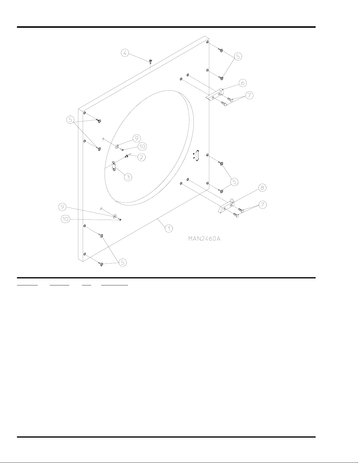
Sensor Bracket Assemblies
Illus. No. Part No. Qty. Description
1 880251 1 1/4” Temperature Sensor Probe Assembly
(includes illus. nos. 1 and 5 through 8)
2 130103 1 225° Automatic Thermostat
3 153010 2 #6 Star Washer
4 152000 2 #6-32 Hex Nut
5 121028 2 Insulated Terminal
6 122701 4 Socket Terminal
7 122605 1 4-Pin Socket Connector
8 154007 2 1/4” Tinnerman Push-On Fastener
9 150005 2 #6-32 x 1/4” Round Head Machine Screw
10 801425 1 Microprocessor Sensor Bracket Assembly Complete
(includes illus. nos. 1 through 10)
305007 1 Universal Sensor Bracket ONLY
11 122604 1 4-Pin Connector
12 122700 4 Pin Terminal
13 150301 2 #8-18 x 7/16” Phillips Pan Head TEK Screw
450215-2 Telephone: 01422 822282 / Fax: 01422 824390 17
Page 18

Direct Spark Ignition Burner Assembly
18 JLA Limited 450215-2
Page 19

Direct Spark Ignition Burner Assembly
Illus. No. Part No. Qty. Description
1 850858 1 Direct Spark Ignition Burner Box ONLY
816125* 1 Natural Gas Burner Assembly
(includes illus. nos. 1 through 8 and 10 through 31)
883532* 1 Liquid Propane Gas Burner Assembly
(includes illus. nos. 1 through 8 and 10 through 31)
883361* 1 D3030 Liquid Propane Conversion Kit
2 884265 1 Ignitor Probe Assembly
884279 1 High Voltage Wire with 1/4” Spade Connection
883031 1 High Voltage Wire with Socket Connection
(for models with spike style connection at module)
3 152013 2 #6-32 Hex Nut
4 150309 2 #10-16 x 1/2” Hex Head TEK Crimptite Screw
5 141105 2 Large Tube Burner
6 150108 2 #8-32 x 1/2” Pan Head Machine Screw
7 128941 1 CE Direct Spark Ignition Module
8 151001 2 #8-32 Pal Nut
9 140819* 2 #30 Burner Orifice (natural gas)
140804* 2 #48 Burner Orifice (liquid propane gas)
10 141230 1 1/2” Direct Spark Ignition Manifold (2-port)
11 318700 1 Pipe Bracket (bent)
12 150300 2 #10 x 1/2” Hex Washer TEK Screw
13 128933 1 1/2” 24 VAC CE Gas Valve (natural gas)
883255 1 1/2” 24 VAC CE Gas Valve (liquid propane gas)
14 141317 1 1/2” Bronze Union Elbow
15 142809 1 1/2” x 29-1/8” Pipe
16 318600 2 Pipe Bracket (bent)
17 150309 4 #10-16 x 1/2” Hex Head TEK Crimptite Screw
18 810029 1 Direct Spark Ignition Module Mounting Bracket
19 142935 1 1/2” B.S.P.T. x 1/2” N.P.T. Transition Coupling
20 150005 2 #6-32 x 1/4” Round Head Machine Screw
21 154004 1 Twin Speed Nut
22 150300 7 #10-16 x 1/2” Hex Washer TEK Screw
23 802799 1 Sail Switch Top and Switch Bracket
24 150303 2 #4 x 3/4” Pan Head “A” Machine Screw
25 122200 1 SPST Sail Switch
26 105500 1 Sail Switch Actuator Rod
27 319202 1 Sail Switch Damper (flat)
28 154002 1 1/8” Push-On Fastener
29 130201 1 330° Hi-Limit Manual Reset
30 319704 1 Hi-Limit Mounting Bracket
31 151000 2 #6-32 Hex Nut
* Consult factory for elevations over 2,000 feet.
450215-2 Telephone: 01422 822282 / Fax: 01422 824390 19
Page 20

Hot Surface Ignition Gas Burner Assembly
20 JLA Limited 450215-2
Page 21

Hot Surface Ignition Gas Burner Assembly
Illus. No. Part No. Qty. Description
1 150301 1 #8-18 x 7/16” Phillips Pan Head TEK Screw
2 128920 1 Hot Surface Ignitor 24V 2-1/2” Long
3 128921 1 Hot Surface Ignition Flame Sensor
4 150309 7 #10-16 x 1/2” Hex Head TEK Crimptite Screw
5 141105 2 Large Tube Burner
6 150108 2 #8-32 x 1/2” Pan Head Machine Screw
7 130201 1 330° Hi-Limit with Manual Reset
8 151001 2 #8-32 Pal Nut
9 140820* 2 #29 Orifice (natural gas)
140804* 2 #48 Orifice (liquid propane gas)
10 141230 1 1/2” Direct Spark Ignition Manifold (2-port)
11 318700 3 Pipe Bracket (bent)
12 150300 7 #10-16 x 1/2” Hex Washer TEK Screw
13 128933 1 CE Gas Valve
883255 1 CE 1/2” Liquid Propane Gas Valve
14 141314 1 90° x 1/2” x 1-1/2” Gas Shutoff Assembly
15 142809 1 1/2” x 29-1/8” Pipe
16 850896 1 Hot Surface Ignition Burner Box ONLY
817066* 1 Hot Surface Ignition Burner Assembly (natural gas)
817067* 1 Hot Surface Ignition Burner Assembly (liquid propane gas)
883361* 1 D3030 Liquid Propane Conversion Kit
17 150001 2 Round Head Machine Screw
18 128975 1 CE Hot Surface Ignition Module
19 810029 1 Hot Surface Ignition Module Mounting Bracket Assembly
20 151000 4 #6-32 Pal Nut
21 154004 1 Twin Speed Nut
22 142935 1 1/2” B.S.P.T. x 1/2” N.P.T. Transition Coupling
23 802799 1 Sail Switch Top and Switch Bracket
24 150303 2 #4 x 3/4” Pan Head “A” Machine Screw
25 122200 1 SPST Sail Switch
26 105500 1 Sail Switch Actuator Rod
27 319202 1 Sail Switch Damper (flat)
28 154002 1 1/8” Push-On Fastener
29 319704 1 Hi-Limit Mounting Bracket
* Consult factory for elevations over 2,000 feet.
450215-2 Telephone: 01422 822282 / Fax: 01422 824390 21
Page 22

Rear Electric Relay Panel Assembly
Illus. No. Part No. Qty. Description
1 151000 2 #6-32 Pal Nut
2 150300 2 #10-16 x 1/2” Hex Washer TEK Screw
3 150008 2 #6-32 x 1-1/4” Phillips Pan Head Machine Screw
4 120716 1 2-Position Terminal Block
5 322812 1 Rear Electric Mounting Plate ONLY
830469 1 Rear Electric Panel Assembly Complete 208-230 Volt 1ø
(includes illus. nos. 1 through 14)
6 822799 1 Transformer Assembly – 230 Volt 1ø
7 136008 2 Fuse Holder
8 136057 2 1/2-Amp (Slo-Blo) Fuse
9 150301 4 #8-18 x 7/16” Phillips Pan Head TEK Screw
10 150297 1 #10 x 1/2” Green Hex Washer TEK Screw
11 152004 1 5/16-18 Hex Nut
12 121010 1 L-70 Ground Lug
13 153002 1 5/16” Lock Washer
14 132496 1 3-Pole Contactor
15 121300 3 Open / Close Bushing
22 JLA Limited 450215-2
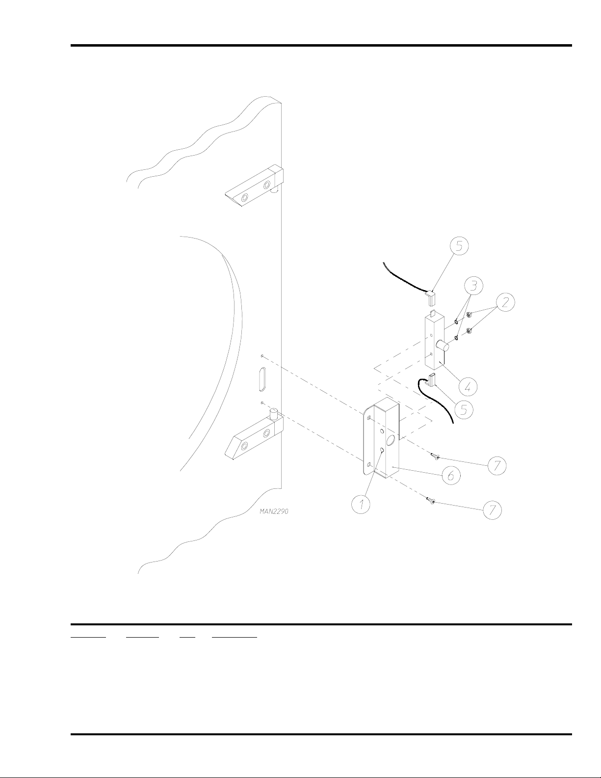
Page 23

S.A.F.E. Temperature Probe Assembly
Illus. No. Part No. Qty. Description
1 822752 1 Sensor Activated Fire Extinguishing Temperature Probe Assembly
(includes illus. nos. 1 through 5)
2 154007 2 Push-On Fastener
3 390390 1 Sensor Bracket ONLY
4 150301 2 #8-18 Phillips Pan Head TEK Screw
5 122647 1 Connector ONLY
450215-2 Telephone: 01422 822282 / Fax: 01422 824390 23
Page 24

S.A.F.E. Solenoid and Piping Assembly
Illus. No. Part No. Qty. Description
1 165114 1 Sensor Activated Fire Extinguishing Solenoid Valve 24V 50/60 Hz
2 143220 1 3/8” F.P.T. Brass Tee
3 143251 1 3/8” M.P.T. Brass Plug
4 143208 2 3/8” Comp x 3/8” M.P.T. Brass Connector
5 143099 6’ 3/8” OD x 0.035 Wall Copper Tubing (sold by the foot)
6 311588 1 Sprinkler Head Mounting Plate
7 143303 1 3/8” N.P.T. Brass Locknut
8 143155 1 3/8” Brass Elbow 90°
9 150309 2 #10 x 1/2” Self-Drilling Screw
10 150301 2 #8-18 x 7/16” TEK Screw
11 143581 1 3 GPM 3/8” F.P.T. Spray Nozzle
12 143177 1 3/4” to 3/8” Bushing for Sensor Activated Fire Extinguishing Solenoid Valve
13 824081 1 R.C. Network Assembly
14 143241 1 3/8” x Close Brass Nipple
15 143315 1 3/8” M.N.P.T. x 1/8” F.N.P.T. Brass Bushing
16 136987 1 Water Jet Pressure Switch
24 JLA Limited 450215-2
Page 25

Outer Top / Back Guard Assemblies
Illus. No. Part No. Qty. Description
1 322809 1 Back Electrical Box Cover
2 150301 4 #8-18 x 7/16” Phillips Pan Head TEK Screw
3 330077 1 Top Back Guard
4 150301 7 #8-18 x 7/16” Phillips Pan Head TEK Screw
5 150301 10 #8-18 x 7/16” Phillips Pan Head TEK Screw
6 312510 1 Outer Top
7 314513 1 Bottom Back Guard
8 150301 13 #8-18 x 7/16” Phillips Pan Head TEK Screw
9 103500 4 Leveling Leg
450215-2 Telephone: 01422 822282 / Fax: 01422 824390 25
Page 26

Additional Parts Available
Part No. Description
112280 “Clean Lint Screen” Label
114001 “CAUTION Exhaust / Lint Screen” Label
120100 3/8” Straight (BX) Connector
120300 3/8” x 45° (BX) Connector
120400 3/8” Red Jacket (BX) Insulator
120500 3/8” Jiffy Clip (BX retainer clip)
120600 3/8” Greenfield (BX)
120707 Terminal Strip (2-position)
120708 Terminal Strip (3-position)
120800 1/4” In-Line Connector
120802 Red Butt Connector
120902 #74B Wire Nut
120903 Crimp-On Wire Nut
121026 Tab Receptacle Combination
121499 5-1/2” Harness Tie
121500 8” Harness Tie
122566 1/4” Insulated (female) Terminal
122804 Manometer (hydro gauge) for Measuring Gas Pressure
404502 White Brush-In-Cap Bottle Touch-Up Paint
26 JLA Limited 450215-2
Page 27

Notes
450215-2 Telephone: 01422 822282 / Fax: 01422 824390 27
Page 28

Part No. 450215 2 - 01/26/09 - 0
 Loading...