

Page 1

SL20/CG20 Parts Manual
Phase 7
COIN & NON-COIN (OPL)
American Dryer Corporation
88 Currant Road
Fall River, MA 02720-4781
T elephone: (508) 678-9000 / Fax: (508) 678-9447
E-mail: techsupport@amdry.com
www .amdry .com
ADC Part No. 450222
Page 2

Retain This Manual In A Safe Place For Future Reference
American Dryer Corporation products embody advanced concepts in engineering, design, and safety. If this product is
properly maintained, it will provide many years of safe, efficient, and trouble free operation.
ONLY qualified technicians should service this equipment.
OBSERVE ALL SAFETY PRECAUTIONS displayed on the equipment or specified in the installation manual included with
the dryer.
The following “FOR YOUR SAFETY” caution must be posted near the dryer in a prominent location.
FOR YOUR SAFETY
Do not store or use gasoline or
other flammable vapors and
liquids in the vicinity of this or
any other appliance.
W e have tried to make this manual as complete as possible and hope you will find it useful. ADC reserves the right to make
changes from time to time, without notice or obligation, in prices, specifications, colors, and material, and to change or
discontinue models.
POUR VOTRE SÉCURITÉ
Ne pas entreposer ni utiliser d’essence
ni d’autres vapeurs ou liquides
inflammables à proximité de cet
appareil ou de tout autre appareil.
Important
For your convenience, log the following information:
DATE OF PURCHASE ____________________________ MODEL NO. __________________________________________
RESELLER’S NAME _______________________________________________________________________________________
Serial Number(s) ________________________________________________________________________________________
________________________________________________________________________________________
________________________________________________________________________________________
Replacement parts can be obtained from your reseller or the ADC factory. When ordering replacement parts from the factory ,
you can F AX your order to ADC at (508) 678-9447 or telephone your order directly to the ADC Parts Department at (508)
678-9000. Please specify the dryer model number and serial number in addition to the description and part number, so that
your order is processed accurately and promptly.
The illustrations on the following pages may not depict your particular dryer exactly. The illustrations are a composite of the
various dryer models. Be sure to check the descriptions of the parts thoroughly before ordering.
“IMPORT ANT NOTE TO PURCHASER”
Information must be obtained from your local gas supplier on the instructions
to be followed if the user smells gas. These instructions must be posted in a
prominent location near the dryer.
Page 3

Table of Contents
Phase 7 OPL Top Panel Assembly
For T op Control Models..................................................................................................................... 2
Phase 7 Coin T op Panel Assembly
For T op Control Models..................................................................................................................... 3
Phase 7 T op Panel Assembly
For Bottom Control Models ............................................................................................................... 4
Front Bottom Panel Assembly................................................................................................................. 5
Main Door Assemblies............................................................................................................................ 6
Middle Front Panel Assembly ................................................................................................................. 7
Lint Drawer Assembly ............................................................................................................................ 8
Basket (Tumbler) Assembly .................................................................................................................... 9
Front Basket (Tumbler)/Support Panel Assembly................................................................................... 10
Rear Support Panel Assembly............................................................................................................... 11
Basket (Tumbler) Roller Wheel Assemblies ........................................................................................... 12
S.A.F .E. System Piping Assembly ......................................................................................................... 13
T emperature Sensor Assemblies............................................................................................................ 14
Motor Drive Assembly.......................................................................................................................... 15
Direct Spark Ignition (DSI) Burner Assembly .................................................................................. 16, 17
Electric Oven Assembly ........................................................................................................................ 18
Lint Box/Blower Motor Assembly ......................................................................................................... 19
Blower Assembly ................................................................................................................................. 20
Blower Motor Assembly ....................................................................................................................... 21
Rear Electrical Panel Assembly
For Gas Models Only ..................................................................................................................... 22
Rear Electrical Panel Assembly
For Electric Models Only................................................................................................................ 23
Heat Duct Assembly ............................................................................................................................. 24
Sail Switch Assembly............................................................................................................................ 25
Base/T op/Sides/Back Guard Assemblies ............................................................................................... 26
Pedestal Box Option............................................................................................................................. 27
Additional Parts Available ..................................................................................................................... 28
Page 4
2
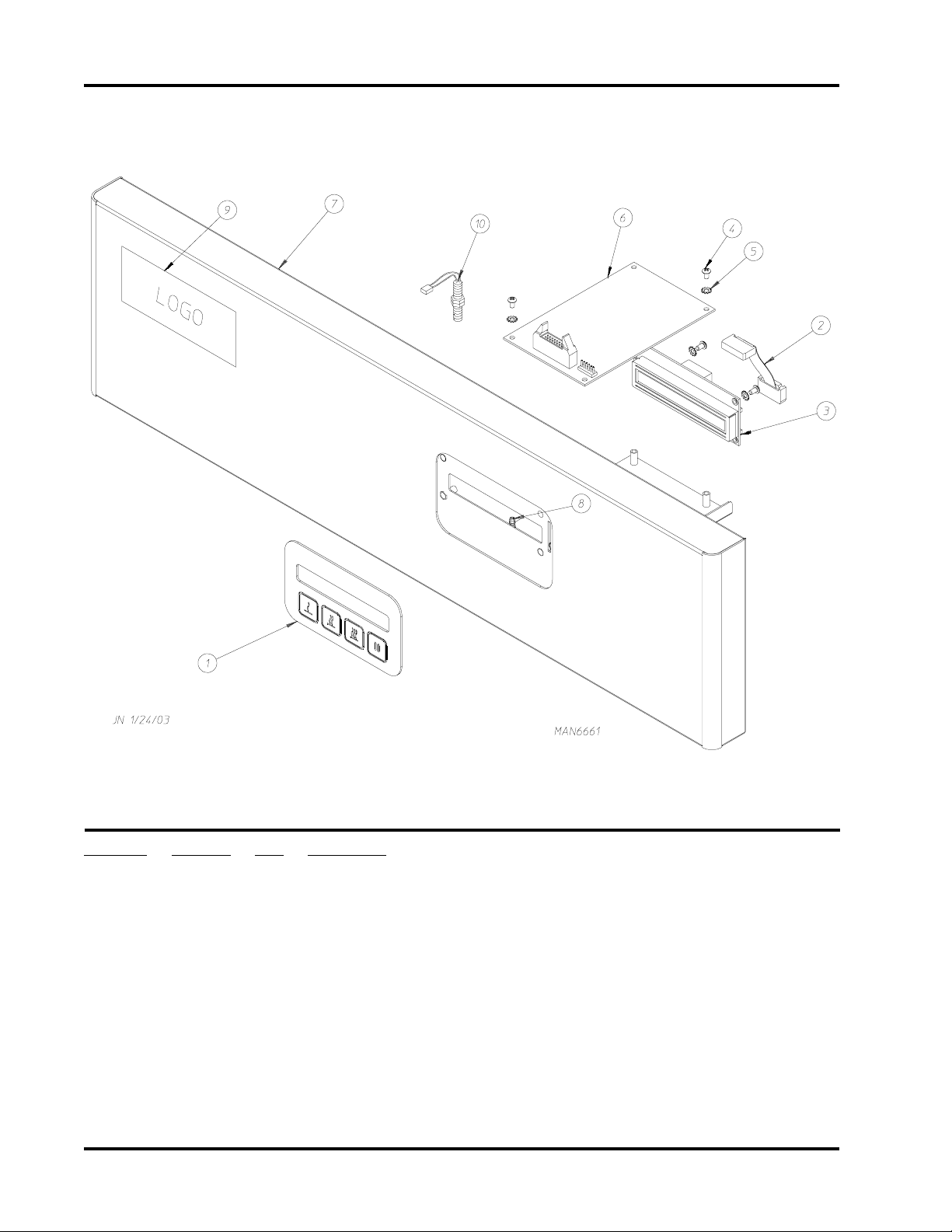
Phase 7 OPL Top Panel Assembly
For T op Control Models
Illus. No. Part No. Qty. Description
1 112579 1 Phase 7 Keyboard
2 137250 1 Phase 7 Ribbon Cable
3 137270 1 16” x 1” Large Character Display
4 150005 4 #6-32 x 1/4” Phillips Round Head Machine Screw
5 153010 4 #6 Star Washer
6 883434 1 Phase 7 Board with Sensor Activated Fire Extinguishing (S.A.F.E.) System
7 818173 1 SL-20 Black Control Panel
818196 1 CG-20 Black Control Panel
8 153603 8 Snap Top Standoff
9 -------* 1 Logo ONLY
10 818206 1 Magnetic Switch Assembly
* Contact reseller for logo.
Page 5
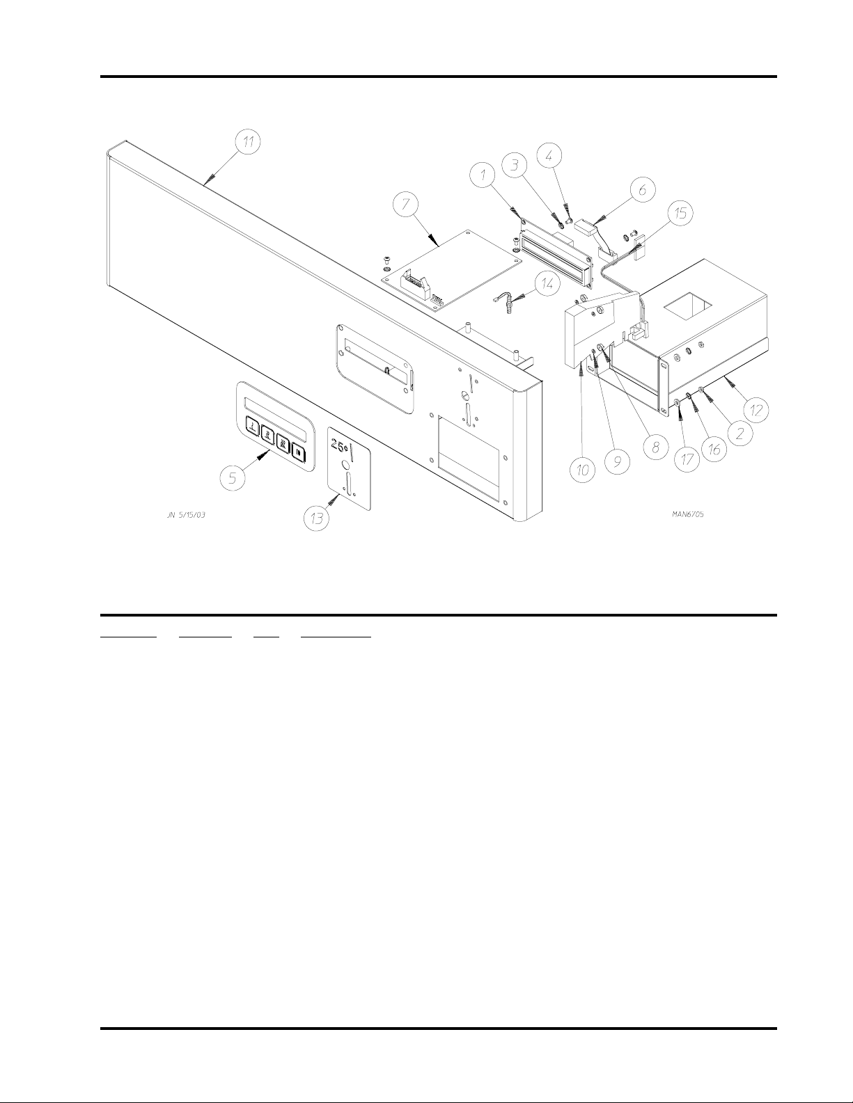
Phase 7 Coin Top Panel Assembly
For T op Control Models
3
Illus. No. Part No. Qty. Description
1 137270 1 16” x 1” Large Character Display
2 152015 4 8-32 Hex Nut
3 153010 4 #6 Internal and External Star Washer Zinc
4 150005 4 6-32 x 1/4” Phillips Round Head Machine Screw
5 112579 1 Phase 7 Keypad
6 137250 1 Phase 7 Ribbon Cable
7 887007 1 Phase 7 Coin Board (without S.A.F.E.)
887009 1 Phase 7 Coin Board (with S.A.F.E.)
8 152016 5 4-40 1/4” Hex Nut
9 153045 5 4 Split Lock Washer
10 883783 1 $0.25 US Coin Acceptor
883784 1 $0.25 Canadian Coin Acceptor
883785 1 0.880 x 0.062 Token Optic Coin Acceptor
883786 1 0.880 x 0.07 Token Optic Coin Acceptor
883787 1 100 Yen Optic Coin Acceptor
11 818181 1 Upper Control Panel (Black)
12 818132 1 Coin V ault
13 318538 1 Faceplate for US Coin
14 818206 1 Magnetic Switch
15 883774 1 Optic Switch
Page 6
4
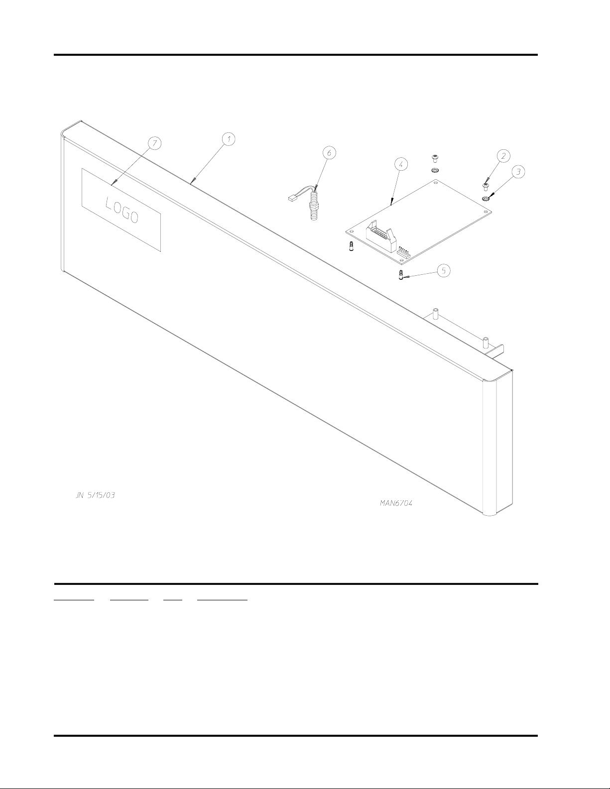
Phase 7 Top Panel Assembly
For Bottom Control Models
Illus. No. Part No. Qty. Description
1 818431 1 SL-20 Black Control Panel
2 150005 4 #6-32 x 1/4” Phillips Round Head Machine Screw
3 153010 4 #6 Star Washer
4 887009 1 Phase 7 Board with Sensor Activated Fire Extinguishing (S.A.F.E.) System
5 153603 4 Snap Top Standoff
6 818206 1 Magnetic Switch Assembly
7 -------* 1 Logo ONLY
* Contact reseller for logo.
Page 7
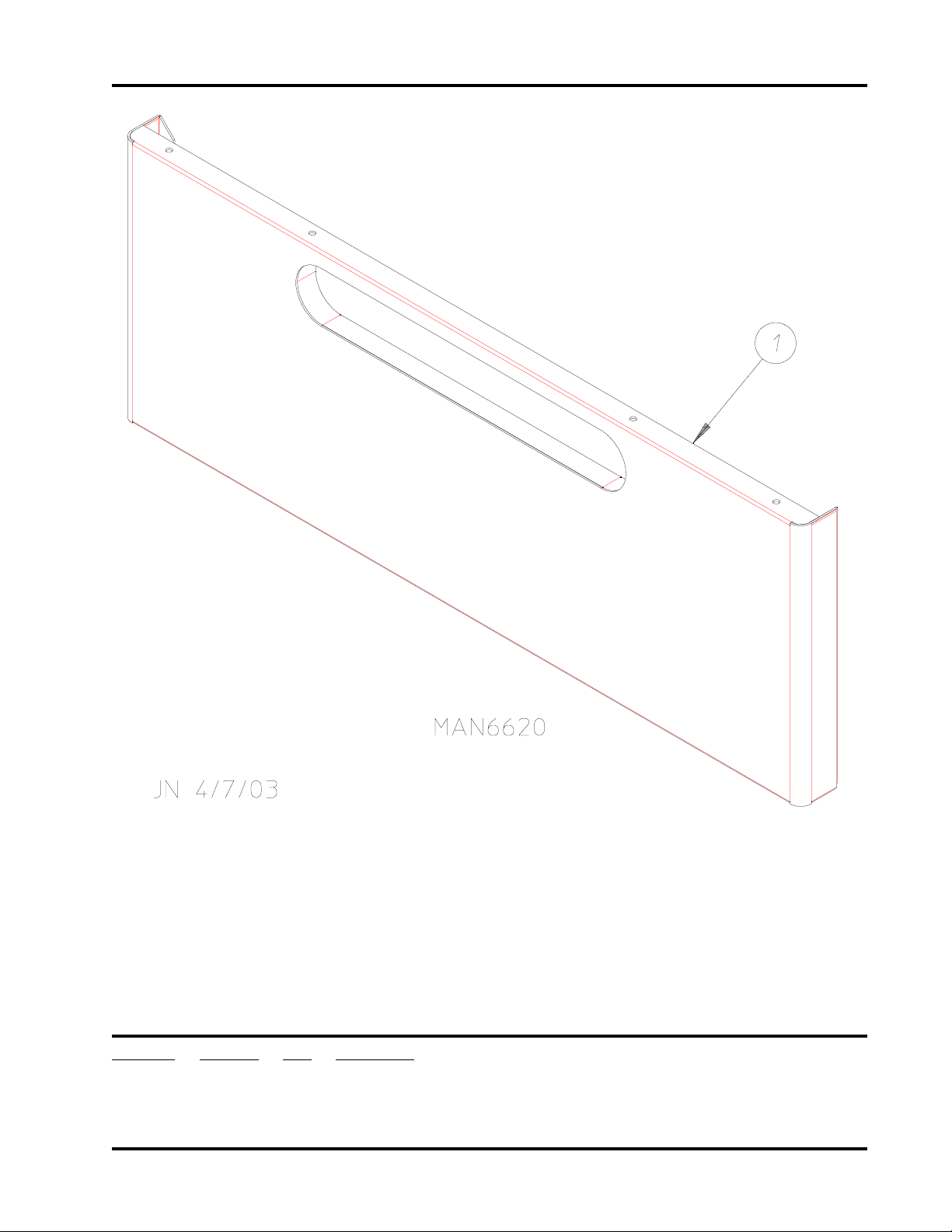
Front Bottom Panel Assembly
5
Illus. No. Part No. Qty. Description
1 818165* 1 Front Bottom Panel Assembly
* Specify color when ordering.
Page 8
6
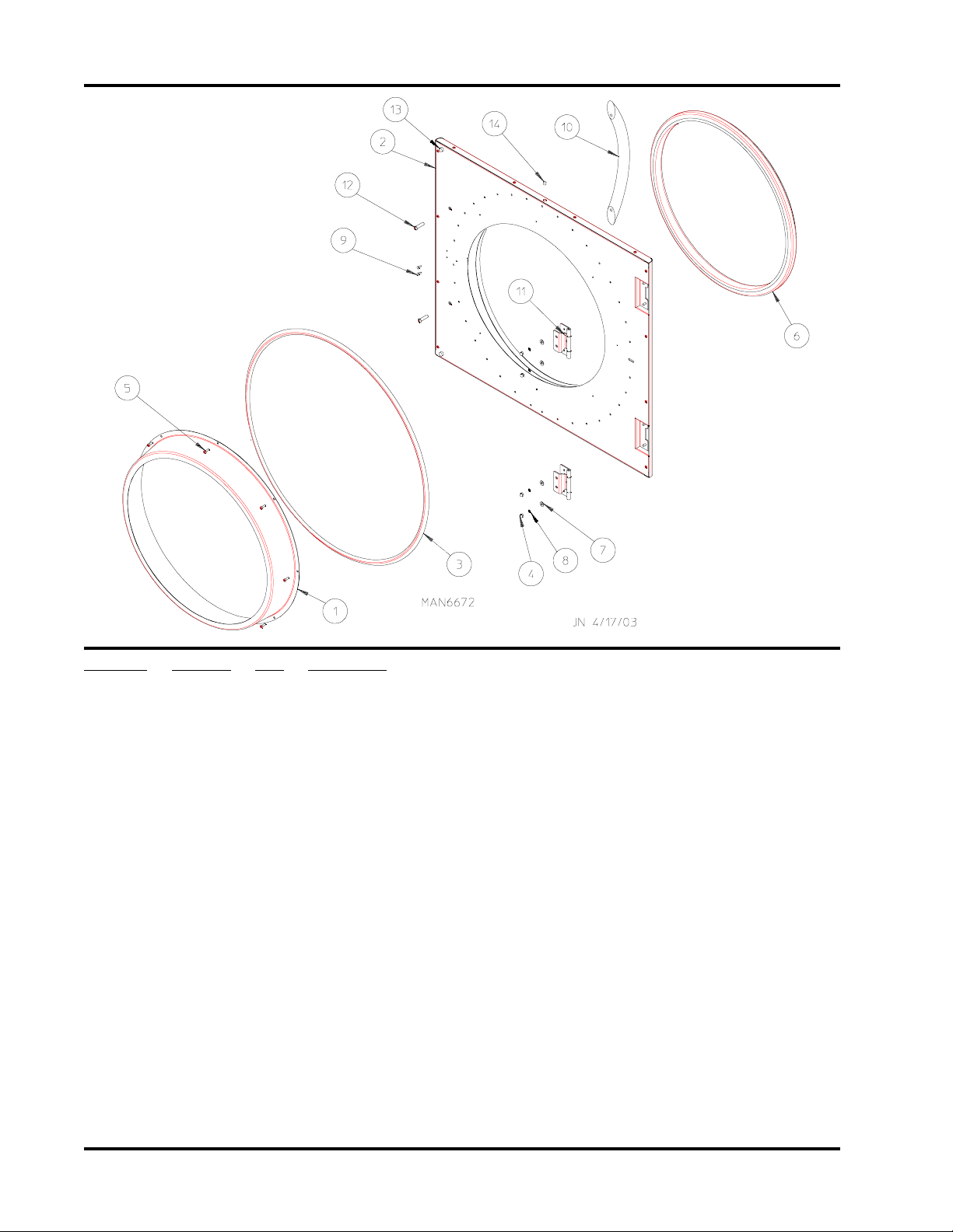
Main Door Assemblies
Illus. No. Part No. Qty. Description
1 883824 1 Door Pan with Glass
2 883823 1 Door (left hinge)
(includes illus. nos. 2, 13 and 14)
883825 1 Door (right hinge)
(includes illus. nos. 2, 13 and 14)
3 102313 1 Door Gasket (fiberglass)
4 151016 4 #8-32 Acorn Nut
5 150322 8 #6 x 1/2” Self-Drilling Screw
6 102314 1 Door Gasket (rubber)
7 153000 4 #8 Flat Washer
8 153012 4 #8 Star Washer
9 150327 2 #6 x 1/2” Phillips Flat Head Screw
10 170230 1 Door Handle
1 1 103079 2 Door Hinge
12 150328 2 1/4-20 x 1” Stainless Steel Phillips Head Screw
13 102384 2 Rubber Bumper
14 170608 1 Magnet
818159 1 Door Assembly Complete (left hinge)
(includes illus. nos. 1 through 14)
818178 1 Door Assembly Complete (right hinge)
(includes illus. nos. 1 through 14)
401010 1 Adhesive for Item (6) Door Gasket (5 oz. tube)...Not Illustrated
Page 9
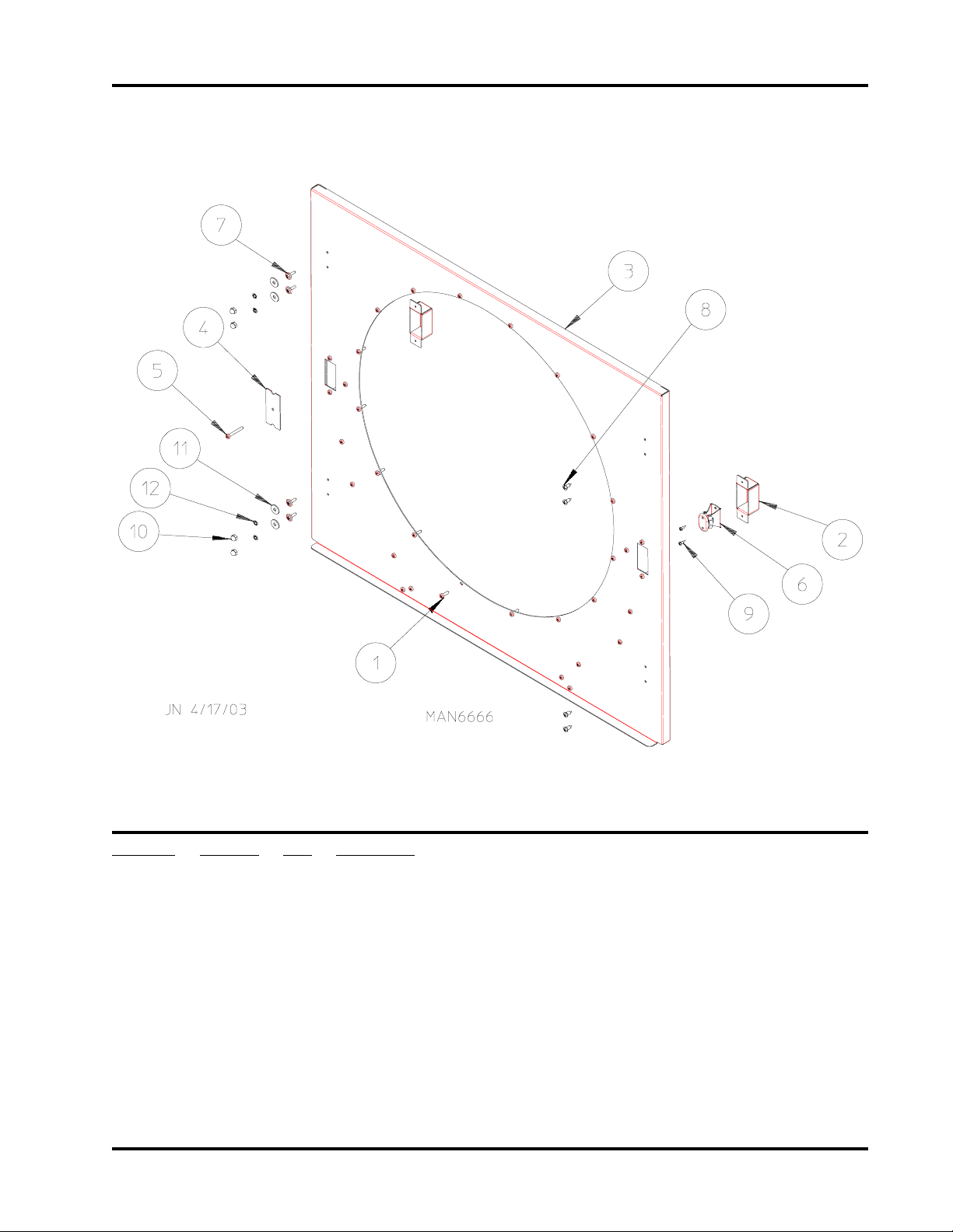
Middle Front Panel Assembly
7
Illus. No. Part No. Qty. Description
1 150322 32 #6 x 1/2” Self-Drilling Screw
2 318146 2 Door Catch Holder
3 818104 1 Middle Front Panel Assembly Complete (specify left or right hinged)
(includes illus. nos. 1 through 9)
4 318249 1 Door Catch Cover
5 150531 1 #6 x 1-1/4” Phillips Pan Sheet Metal Screw
6 170228 1 Door Catch
7 150399 4 #8 x 1/2” Phillips Self-Drilling Screw (for models without hinge studs)
8 150301 4 #8 x 7/16” Phillips Pan Head TEK Screw
9 150329 2 #4 x -3/8 Phillips Pan Head Machine Screw
10 151016 4 #8 Acorn Nut (for models with hinge studs)
11 153000 4 #8 Flat Washer (for models with hinge studs)
12 153012 4 #8 Star Washer (for models with hinge studs)
Page 10
8
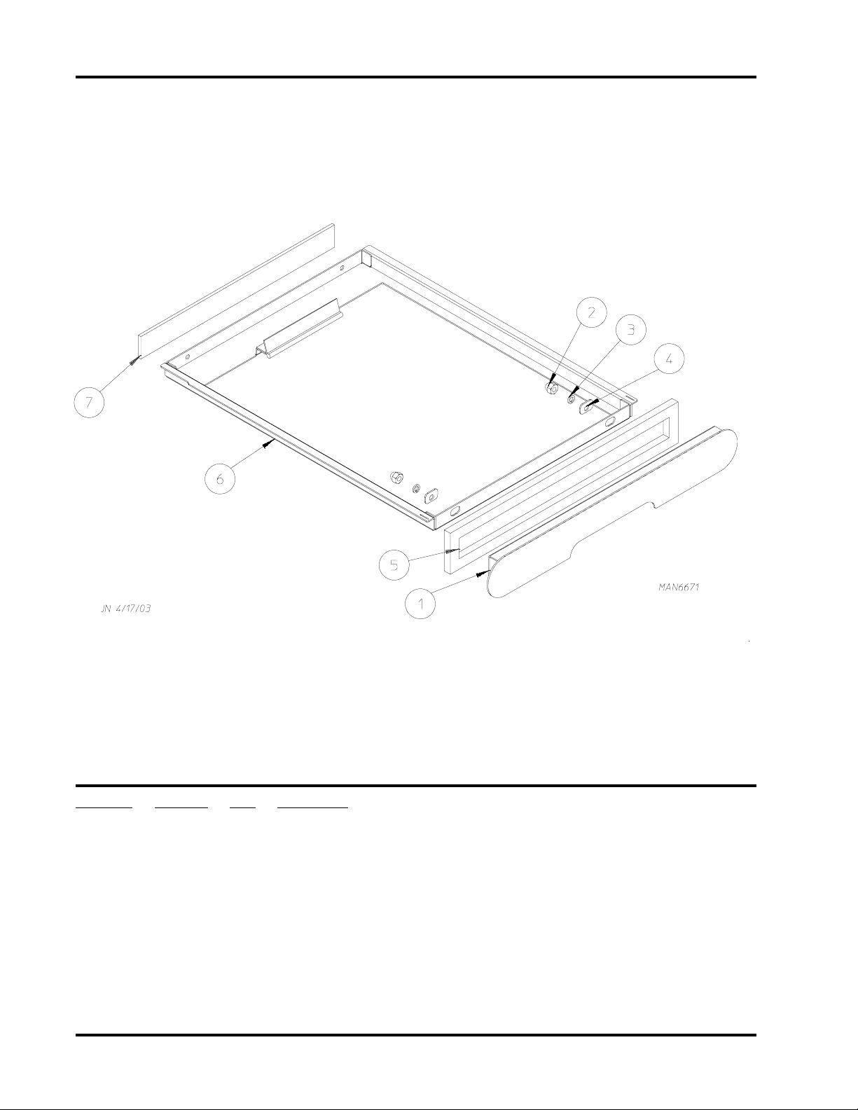
Lint Drawer Assembly
Illus. No. Part No. Qty. Description
1 883751 1 Lint Drawer Handle
(includes illus. nos. 1 through 5)
2 151010 2 #10-32 Hex Acorn Lock Nut
3 153420 2 #10 Split Lock Washer
4 318541 2 Offset Washer
5 117605 2 Gasket (sold by the foot)
6 883752 1 Lint Drawer Assembly
(includes illus. nos. 6 and 7)
7 116054 1 Lint Drawer Felt
818166 1 Lint Draw Complete with Handle
(includes illus. nos. 1 through 7)
Page 11

Basket (T umbler) Assembly
9
Illus. No. Part No. Qty. Description
1 884359 1 Open Back Tumbler Assembly
884363 1 Solid Back T umbler Assembly
(as of May 2004)
(includes illus. nos. 1 through 8)
2 318242 3 5” Tapered Rib
3 150313 12 #10-16 x 1/2” TORX Screw
4 154217 1 1/8” x 1/2” Pop Rivet
5 102102 1 Rotational Sensor Magnet
401010 1 Adhesive for Felt Collar (5 oz. tube)
6 115906 2 Basket (tumbler) Felt
Page 12

10
Front Basket (Tumbler)/Support Panel Assembly
Illus. No. Part No. Qty. Description
1 883820 1 Front Basket (tumbler) Support Panel Complete
2 818110 1 Front Right Wheel Assembly
(refer to Basket [Tumbler] Roller Wheel Assemblies on page 12)
3 818109 1 Front Left Wheel Assembly
(refer to Basket [Tumbler] Roller Wheel Assemblies on page 12)
4 121400 1 Universal Bushing
Page 13

Rear Support Panel Assembly
11
Illus. No. Part No. Qty. Description
1 818207 1 T emperature Sensor Probe Assembly
(refer to Temperature Sensor Assemblies on page 14)
2 318252 1 Rear Temperature Probe Mount
3 318234 1 Rotational Sensor Switch Bracket
4 152015 2 #8-32 Hex Nut
5 153000 2 #8 Flat Washer
6 153012 2 #8 Star Washer
7 153009 9 #10 Star Washer
8 152008 9 #10-32 Hex Nut
9 154200 12 5/32” x 5/16” Pop Rivet
10 154007 2 1/4” Push On Fastener
11 318342 1 Rear Basket (tumbler) Support Panel
12 122325 1 Magnetic Rotational Sensor Switch
13 150300 8 #10-16 x 1/2” Hex Washer TEK Screw
14 818109 1 Rear Right Roller Wheel Assembly
(refer to Basket [Tumbler] Roller Wheel Assemblies on page 12)
15 8181 10 1 Rear Left Roller Wheel Assembly
(refer to Basket [Tumbler] Roller Wheel Assemblies on page 12)
16 818145 1 Rear Bulkhead Assembly with Sensor Activated Fire Extinguishing
(S.A.F.E.) System Piping Assembly
(refer to S.A.F.E. System Piping Assembly on page 13)
81811 1 1 Rear Bulkhead without Sensor Activated Fire Extinguishing (S.A.F.E.)
System
17 156001 1 Caterpillar Grommet
Page 14

12
Basket (T umbler) Roller Wheel Assemblies
Illus. No. Part No. Qty. Description
1 150510 3 1/4-20 x 3/4” Hex Head Machine Bolt
2 154267 1 M10 x 25mm Shoulder Screw
3 153007 3 1/4” Split Lock Washer
4 153002 1 5/16” Split Lock Washer
5 154013 1 M8 Hex Nut
6 154284 1 Basket (tumbler) Wheel Spacer
7 318232 1 Rear Left/Front Right Roller Wheel Bracket
818110 1 Rear Left/Front Right Wheel Assembly Complete
(includes illus. nos. 1 through 10)
318233 1 Rear Right/Front Left Roller Wheel Bracket
818109 1 Rear Right/Front Left Wheel Assembly Complete
(includes illus. nos. 1 through 10)
8 153596 3 1/4-20 Clinch Nut
9 153018 3 1/4” Flat Washer
10 180032 1 Idler Wheel
Page 15

S.A.F.E. System Piping Assembly
13
Illus. No. Part No. Qty. Description
1 143581 1 3 GPM 3/8” N.P.T. Spray Nozzle
2 318167 1 Nozzle Bracket
3 143220 2 3/8” F.P.T. Brass Tee
4 143242 1 3/8” x 2-1/2” Brass Nipple
5 143208 2 3/8” Comp x 3/8” M.P.T. Brass Connector
6 143155 3 3/4” Brass Street Elbow
7 143315 1 3/8” M.P.T. x 1/8” Brass Bushing
8 136987 1 W ater Jet Pressure Switch
9 165114 1 Solenoid V alve
10 143251 1 3/8” M.P.T. Brass Plug
11 142888 1 1/2” M.P.T. x 3/8” F.P.T. Hex Bushing
12 143099 1 3/8” OD Copper Tube
13 143303 1 3/8” N.P.T. Brass Lock Nut
14 818139 1 Rear Bulkhead Assembly for Sensor Activated Fire Extinguishing (S.A.F.E.)
System ONLY
818199 1 Sensor Activated Fire Extinguishing (S.A.F.E.) System Piping Assembly
(includes illus. nos. 1 through 15)
15 824081 1 R.C. Network with Terminals
16 150300 2 #10-16 x 1/2” Hex Washer TEK Screw
17 152008 2 #10 Nut
18 152034 2 #10 Split Lock Washer
Page 16

14
T emperatur e Sensor Assemblies
Illus. No. Part No. Qty. Description
1 818207 2 Basket (tumbler) Temperature Sensor Probe
(includes illus. nos. 1 through 3)
2 122646 1 2-Pin Plug
3 122706 2 Socket Terminal ONLY
4 883821 1 Sensor Activated Fire Extinguishing (S.A.F.E.) System Temperature Sensor
Probe Assembly Complete
(includes illus. nos. 4 through 8)
5 122646 1 2-Pin Plug
6 122706 2 Socket Terminal ONLY
7 318525 1 Sensor Activated Fire Extinguishing (S.A.F.E.) System Probe Bracket
8 154007 2 Push On Fasteners
Page 17

Motor Drive Assembly
15
Illus. No. Part No. Qty. Description
1 154279 4 5/16-18 x 3/4” Carriage Bolt (for motor bases without studs)
2 153002 4 5/16” Split Lock Washer
3 154321 1 5/16” x 3/8” Allen Setscrew
4 152004 4 5/16-18 Hex Nut
5 153001 4 5/16” Flat Washer
6 1 8 112 0 1 4-Pole Motor (for earlier models without studs)
7 318247 1 4-Pole Motor Sheave (60 Hz models)
318248 1 4-Pole Motor Sheave (50 Hz models)
8 318548 1 Motor Base
9 100197 1 Drive Belt
818121 1 Drive Motor Assembly 60 Hz
(includes illus. nos. 1 through 8)
818126 1 Drive Motor Assembly 50 Hz
(includes illus. nos. 1 through 8)
10 818200 1 Motor Base Plate (for later models with studs)
Page 18

16
Direct Spark Ignition (DSI) Burner Assembly
Page 19

Direct Spark Ignition (DSI) Burner Assembly
Illus. No. Part No. Qty. Description
1 143226 1 1/2” Brass Street Elbow
2 141317 1 1/2” Bronze Union Elbow
3 882451 1 Ignitor Probe Assembly with High Voltage (HV) Wire
(includes illus. nos. 3 and 16)
4 128927 1 1/2” 24 VAC Redundant (natural gas) Gas Valve
880960 1 1/2” 24 VAC Redundant (liquid propane) Gas Valve
5 140868 1 #31 Burner Orifice (natural gas) ONLY (40K BTU Burners)
140870 1 #34 Burner Orifice (natural gas) ONLY (35K BTU Burners)
140869 1 #49 Burner Orifice (liquid propane [L.P.] gas) ONLY (40 K BTU Burners)
140871 1 #51 Burner Orifice (liquid propane [L.P.] gas) ONLY (35 K BTU Burners)
6 141129 1 Inshot Burner
7 318293 1 Commercial Electric Oven Housing ONLY
818163 1 Direct Spark Ignition (DSI) Gas Train Assembly Complete (natural gas)
(includes illus. nos. 1 through 14)
883610 1 Liquid Propane (L.P.) Conversion Kit (includes orifice) (40 K BTU Burners)
883799 1 Liquid Propane (L.P.) Conversion Kit (includes orifice) (35 K BTU Burners)
8 318345 1 Commercial Gas Oven Mounting Bracket
9 318395 1 Burner Retainer Clip
10 142953 1 3/8” x 1/2” Steel Bushing
11 818177 1 Gas Burner Mounting Bracket
12 318519 1 Gas Valve Support Bracket
13 150300 1 2 #10-16 x 1/2” Hex Washer TEK Screw
14 142634 1 3/8” x 19” Pipe Nipple
15 128935 1 Direct Spark Ignition (DSI) Module with Three (3) T ries
16 128919 1 High Voltage (HV) Ignition Cable with Cap
17 152013 2 #6-32 Hex Nut
17
Page 20

18
Electric Oven Assembly
Illus. No. Part No. Qty. Description
1 318543 1 Electric Oven Housing
2 318294 1 Electric Oven Mounting Bracket
3 120086 1 3-Phase (3ø) Oven (5.4 kW at 240 volt or 8.1 kW at 416 volt)
818155 1 Electric Oven Assembly Complete
(includes illus. nos. 1 through 9)
4 150300 6 #10-16 x 1/2” Hex Washer TEK Screw
5 130400 1 T emperature Sensor
6 153022 4 #10 Flat Washer
7 153024 9 #10 Split Lock Washer
8 152008 9 #10-32 Hex Nut
9 121011 1 Bus Bar
Page 21

Lint Box/Blower Motor Assembly
19
Illus. No. Part No. Qty. Description
1 818207 1 T emperature Sensor Probe Assembly
(refer to Temperature Sensor Assemblies on page 14)
2 100623 1 25 M.F.D. 440 VAC Capacitor (for use with 120 volt blower)
100633 1 6 M. F.D. 440 VAC Capacitor (for use with 220 volt blower)
3 318230 1 Capacitor Bracket (for use with 25 M.F.D. 440 VAC Capacitor)
100632 1 Capacitor Bracket (for use with 6 M.F.D. 440 VAC Capacitor)
4 318224 1 Blower Housing Rear Support Bracket
5 130119 1 Automatic Reset Hi-Limit Thermostat
6 122002 1 Door Switch
7 154007 2 1/4” Push On Fastener
8 150301 11 #8-18 x 7/16” Phillips Pan Head TEK Screw
9 150309 2 #10-16 x 1/2” Hex Head TEK Crimptite Screw
10 152013 2 #6-32 Hex Nut
11 152008 4 #10-32 Hex Nut
12 153049 4 13/64” x 7/8” Flat Washer
13 318192 1 Lint Box T op
14 818095 1 Lint Box
15 818100 1 120 Volt Blower Assembly
(refer to Blower Assembly on page 20)
818147 1 220 Volt Blower Assembly
(refer to Blower Assembly on page 20)
16 153024 4 #10 Split Lock Washer
17 1 17605 1 1/4” x 3/8” Sponge Tape (sold by the foot)
18 1 17604 1 Noise Suppression Tape (sold by the foot)
19 1 17604 1 Noise Suppression Tape (sold by the foot)
20 318179 1 Exhaust Tube
21 143335 1 Exhaust Transition Piece
Page 22

20
Blower Assembly
Illus. No. Part No. Qty. Description
1 883826 1 Motorized Impellor 120V ONLY
(refer to Blower Motor Assembly on page 21)
883827 1 Motorized Impellor 240V ONLY
(refer to Blower Motor Assembly on page 21)
2 318204 1 Blower Housing Mount
3 150300 8 #10-16 x 1/2” Hex Washer Screw
4 154338 5 M4 x 6mm Phillips Head Slotted Machine Screw
5 152008 4 #10-32 Hex Nut
6 153024 4 #10 Split Lock Washer
7 153012 5 #8 Star Washer
8 818099 1 Blower Housing
9 318179 1 Exhaust T ube
10 143335 1 Exhaust Transition Piece
818100 1 Blower Assembly Complete 120V
(includes illus. nos. 1 through 10)
818147 1 Blower Assembly Complete 240V
(includes illus. nos. 1 through 10)
1 1 154215 2 5/32” Pop Rivet
Page 23

Blower Motor Assembly
21
Illus. No. Part No. Qty. Description
1 883826 1 120V Motorized Impellor with Plug
(includes illus. nos. 1 through 4)
883827 1 240V Motorized Impellor with Plug
(includes illus. nos. 1 through 4)
100624 1 Motorized Impellor 240V (50 Hz)
100621 1 Motorized Impellor 120V (60 Hz)
2 121000 2 1/4” x 0.032 Uninsulated Term
3 122622 1 4-Pin Plug
4 122705 2 Socket Terminal ONLY
Page 24

22
Rear Electrical Panel Assembly
For Gas Models ONLY
Illus. No. Part No. Qty. Description
1 818189 1 Electrical Panel Assembly
818229 1 Rear Electrical Panel Complete 120V (60 Hz)
(includes illus. nos. 1 through 15)
818227 1 Rear Electrical Panel Complete 240V (50 Hz)
(includes illus. nos. 1 through 15)
2 131932 3 24V SPST Relay
3 120730 1 30-Position T erminal Block
4 818212 1 Transformer Assembly - 120V (60 Hz)
818224 1 Transformer Assembly - 240V (50 Hz)
5 120716 1 2-Position T erminal Block
6 114506 1 Fuse Replacement Label
7 136057 1 1/2-Amp (Slo-Blo) Fuse
8 136008 1 Fuse Holder
9 121400 3 7/8” Bushing
10 121010 2 Ground Lug
1 1 150002 2 #6-32 x 1” Phillips Round Head Machine Screw
12 151001 2 #8-32 Pal Nut
13 120910 2 #10-32 Green Ground Screw
14 150301 9 #8-18 x 7/16” Phillips Pan Head TEK Screw
15 151000 2 #6-32 Pal Nut
Page 25

Rear Electrical Panel Assembly
For Electric Models ONL Y
23
Illus. No. Part No. Qty. Description
1 818190 1 Electrical Panel Assembly
818332 1 Rear Panel Assembly Complete 240V 1ø to 416V 3ø
(includes illus. nos. 1 through 14)
2 131932 3 24V SPST Relay
3 131368 1 25-Amp Contactor
4 818224 1 Transformer Assembly
5 120728 1 4-Position T erminal Block
6 114506 1 Fuse Replacement Label
7 136057 1 1/2-Amp (Slo-Blo) Fuse
8 136008 1 Fuse Holder
9 121400 3 7/8” Bushing
10 121010 3 Small Ground Lug
11 150301 9 #8-18 x 7/16” Phillips Pan Head TEK Screw
12 151001 2 #8-32 Pal Nut
13 120910 3 #10-32 Green Ground Screw
14 151000 2 #6-32 Pal Nut
Page 26

24
Heat Duct Assembly
Illus. No. Part No. Qty. Description
1 130403 1 330º F Thermostat (for gas models Only)
2 318289 1 Heat Duct Cover Commercial Electric
3 150300 20 #10-16 x 1/2” Hex Washer TEK Screw
4 153012 2 #8 Star Washer
5 152015 2 #8 Hex Nut
6 153000 2 #8 Flat Washer
7 818154 1 Heat Duct
8 818114 1 Top Wire Sail Switch Assembly
(refer to Sail Switch Assembly on page 25)
9 883821 1 Sensor Activated Fire Extinguishing (S.A.F.E.) System Temperature Sensor
(refer to Temperature Sensor Assemblies on page 14)
10 318545 1 Sensor Hole Cover Plate (for electric models Only)
1 1 152008 9 #10 Nut
12 154200 9 #10 Split Lock Washer
Page 27

Sail Switch Assembly
25
Illus. No. Part No. Qty. Description
1 154002 1 1/8” Push On Fastener
2 332689 1 Sail Switch Damper (flat)
3 150309 4 #10-16 x 1/2” Hex Head TEK Crimptite Screw
4 122200 1 Sail Switch ONLY
5 154004 1 T win Speed Nut
6 150303 2 #4 x 3/4” Pan Head “A” Machine Screw
7 318237 1 Sail Switch Box
8 105500 1 Sail Switch Rod Assembly
9 818113 1 Sail Switch Box Cover and Bracket ONLY
818114 1 Sail Switch Assembly Complete
(includes illus. nos. 1 through 9)
10 121400 1 Universal Bushing
Page 28

26
Base/Top/Sides/Back Guard Assemblies
Illus. No. Part No. Qty. Description
1 318398 1 SL-20 Back Guard
318222 1 CG-20 Back Guard
818168 1 SL-20 Back Guard Assembly Complete
(includes illus. nos. 1 through 4)
818179 CG-20 Back Guard Assembly Complete
(includes illus. nos. 1 through 4)
2 318397 1 Gas Pipe Pocket
3 150300 32 #10-16 x 1/2” Hex Washer TEK Screw
4 318272 1 Junction Box Cover
5 103501 4 Leveling Leg
6 152014 8 1/4-20 Free Spin Wash Nut
7 818102 1 Base
818142 1 Base Assembly Complete
(includes illus. nos. 5 through 7)
8 318159 1 Exhaust Support Bracket
9 818129 1 SL-20 T op
818137 1 CG-20 T op
10 318340 1 SL-20 Right Side Panel
318275 1 CG-20 Right Side Panel
1 1 318341 1 SL-20 Left Side Panel
318274 1 CG-20 Left Side Panel
12 154210 * 5/32” x 3/16” Pop Rivet
13 318143 * Top Catch Spacer
14 318213 1 Center Wire Track
15 156001 2 Caterpillar Grommet
* As required
Page 29

Pedestal Box Option
27
Illus. No. Part No. Qty. Description
1 818313 1 Dryer Pedestal
Page 30

28
Part No. Description
112280 “Clean Lint Screen” Label
114006 “WARNING - Fire Hazards” Label
114548 Phase 7 Program Location Summary Label
404519 Black Touch-Up Paint
120903 Crimp-On Wire Nut
121499 5-1/2” Harness Tie
122804 Manometer (hydro gauge) for Measuring Gas Pressure
114094 Warning Arc Label
112017 ADC Logo Label
114007 “Danger High Voltage”Label
112014 “Caution Rotating Parts”Label
114001 “Caution...Combustable Lint”Label
112046 “Important...earth ground” Label
Additional Parts Available
Page 31

Notes _________________________________________________________________________
_______________________________________________________________________________
_______________________________________________________________________________
_______________________________________________________________________________
_______________________________________________________________________________
_______________________________________________________________________________
_______________________________________________________________________________
_______________________________________________________________________________
_______________________________________________________________________________
_______________________________________________________________________________
_______________________________________________________________________________
_______________________________________________________________________________
_______________________________________________________________________________
_______________________________________________________________________________
_______________________________________________________________________________
_______________________________________________________________________________
_______________________________________________________________________________
_______________________________________________________________________________
_______________________________________________________________________________
_______________________________________________________________________________
_______________________________________________________________________________
_______________________________________________________________________________
_______________________________________________________________________________
_______________________________________________________________________________
_______________________________________________________________________________
_______________________________________________________________________________
_______________________________________________________________________________
_______________________________________________________________________________
_______________________________________________________________________________
_______________________________________________________________________________
_______________________________________________________________________________
_______________________________________________________________________________
_______________________________________________________________________________
_______________________________________________________________________________
_______________________________________________________________________________
Page 32

ADC 450222 4-05/04/06-0
 Loading...