

Page 1
SUPER AD-50 Parts Manual
24 VAC
1994 thru 2001
MODELS: ADG-50DS
ADE-50S
ADS-50S
American Dryer Corporation
88 Currant Road
Fall River, MA 02720-4781
Telephone: (508) 678-9000 / Fax: (508) 678-9447
E-mail: techsupport@amdry.com
www.amdry.com
ADC Part No. 450302
Page 2

Retain This Manual In A Safe Place For Future Reference
American Dryer Corporation products embody advanced concepts in engineering, design, and safety. If this product is
properly maintained, it will provide many years of safe, efficient, and trouble-free operation.
ONLY qualified technicians should service this equipment.
OBSERVE ALL SAFETY PRECAUTIONS displayed on the equipment or specified in the installation manual included with
the dryer.
The following “FOR YOUR SAFETY” caution must be posted near the dryer in a prominent location.
FOR YOUR SAFETY
Do not store or use gasoline or
other flammable vapors or liquids
in the vicinity of this or any other
appliance.
We have tried to make this manual as complete as possible and hope you will find it useful. ADC reserves the right to make
changes from time to time, without notice or obligation, in prices, specifications, colors, and material, and to change or
discontinue models.
POUR VOTRE SÉCURITÉ
Ne pas entreposer ni utiliser d’essence
ni d’autres vapeurs ou liquides
inflammables dans le voisinage de cet
appareil ou de yout autre appareil.
Important
For your convenience, log the following information:
DATE OF PURCHASE ____________________________ MODEL NO. __________________________________________
RESELLER’S NAME _______________________________________________________________________________________
Serial Number(s) ________________________________________________________________________________________
________________________________________________________________________________________
SUPER AD-50
________________________________________________________________________________________
Replacement parts can be obtained from your reseller or the ADC factory. When ordering replacement parts from the factory,
you can FAX your order to ADC at (508) 678-9447 or telephone your order directly to the ADC Parts Department at (508)
678-9000. Please specify the dryer model number and serial number in addition to the description and part number, so that
your order is processed accurately and promptly.
The illustrations on the following pages may not depict your particular dryer exactly. The illustrations are a composite of
the various dryer models. Be sure to check the descriptions of the parts thoroughly before ordering.
“IMPORTANT NOTE TO PURCHASER”
Information must be obtained from your local gas supplier on the instructions
to be followed if the user smells gas. These instructions must be posted in a
prominent location near the dryer.
Page 3

Table of Contents
Control Door Assembly Without Trim
For Non-Coin Models Mfd. as of July 13, 1998 ............................................................................... 3
High Security Control Door Assembly
For All Coin Models and Non-Coin Models Mfd. prior to July 13, 1998 ........................................... 4
Phase 5 Coin Microprocessor Control Panel Assembly ........................................................................... 5
Phase 5 Non-Coin Microprocessor Control Panel Assembly ................................................................... 6
Phase 5 Coin and Non-Coin Microprocessor Control Box Assembly ...................................................... 7
Dual Timer “Tap Touch” Controls
For Models Mfd. as of November 3, 2000 ....................................................................................... 8
Dual Timer Control Panel Assembly
For Models Mfd. prior to November 3, 2000 ................................................................................... 9
Dual Timer Control Box Assembly ........................................................................................................ 10
Non-Microprocessor Coin Meter Control Panel Assembly .................................................................... 11
Non-Microprocessor Coin Meter Control Box Assembly ...................................................................... 12
Coin Meter Replacement Parts ............................................................................................................. 13
Coin Vault Assembly ............................................................................................................................. 14
“Plastic” Main Door Assembly .............................................................................................................. 15
Main Door Switch Assembly For “Plastic” Door ................................................................................... 16
Front Panel Assembly For “Plastic” Door .............................................................................................. 17
Main Door “Steel” Assembly ................................................................................................................ 18
Main Door Switch Assembly Cold Rolled Steel Door ............................................................................ 19
Cold Rolled Steel Door Front Panel ...................................................................................................... 20
Lint Trap Assembly ............................................................................................................................... 21
Drop Lint Door Assembly Without Trim
For Non-Coin Models Mfd. as of July13, 1998 .............................................................................. 22
Drop Lint Door Assembly With Trim
For All Coin Models and Non-Coin Models Mfd. prior to July 13, 1998 ......................................... 23
Page 4

Tumbler/Support Assemblies ................................................................................................................. 24
Idler Bearing Assembly ......................................................................................................................... 25
Tumbler Bearing Assembly .............................................................................................................. 26, 27
Non-Reversing Totally Enclosed, Fan-Cooled Motor Mount Assembly............................................ 28, 29
Reversing Totally Enclosed, Fan-Cooled Motor Mount Assembly .................................................... 30, 31
Sensor Bracket Assemblies ............................................................................................................. 32, 33
Direct Spark Ignition Burner Assembly ............................................................................................ 34, 35
Electric Oven Assembly .................................................................................................................. 36, 37
Steam Coil/Air Operated Steam Damper Assembly ......................................................................... 38, 39
Sail Switch/Hi-Limit Assembly .............................................................................................................. 40
Single-Phase (1Ø) Motor, Electric Relay Panel Assembly ...................................................................... 41
3-Phase (3Ø) Motor, Electric Relay Panel Assembly ............................................................................. 42
Microprocessor Reversing Rear Control Box Assembly......................................................................... 43
Dual Timer Reversing Rear Control Box Assembly ................................................................................ 44
Outer Top/Back Guard Assemblies ....................................................................................................... 45
Electric Oven Chart .............................................................................................................................. 46
Transformer Listing Gas/Steam Dryers .................................................................................................. 47
Transformer Usage Listing For Electric Dryers ....................................................................................... 48
Microprocessor Coin Acceptors Listing ................................................................................................ 49
Additional Parts Available ..................................................................................................................... 50
Page 5
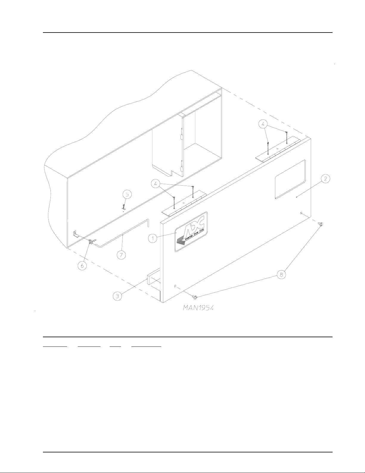
Control Door Assembly Without Trim
For Non-Coin Models Mfd. as of July 13, 1998
Illus. No. Part No. Qty. Description
1 881053 1 ADC Logo Only (with double adhesive tape)
870011 1 Logo Double Tape Kit
2 882265* 1 Control Door
(includes illus. nos. 2 and 3)
3 117604 4 Neoprene Sponge Tape (sold by the foot)
4 150300 4 #10 x 1/2” Hex Washer TEK Screw
5 102603 1 Control Door Rod Support Catch
6 102601 1 Control Door Retainer Clip
7 102502 1 Control Door Support Rod
8 882541 2 Spring Turn Latch Assembly
* Specify color when ordering.
450302-5 Telephone: (508) 678-9000 / www.amdry.com 3
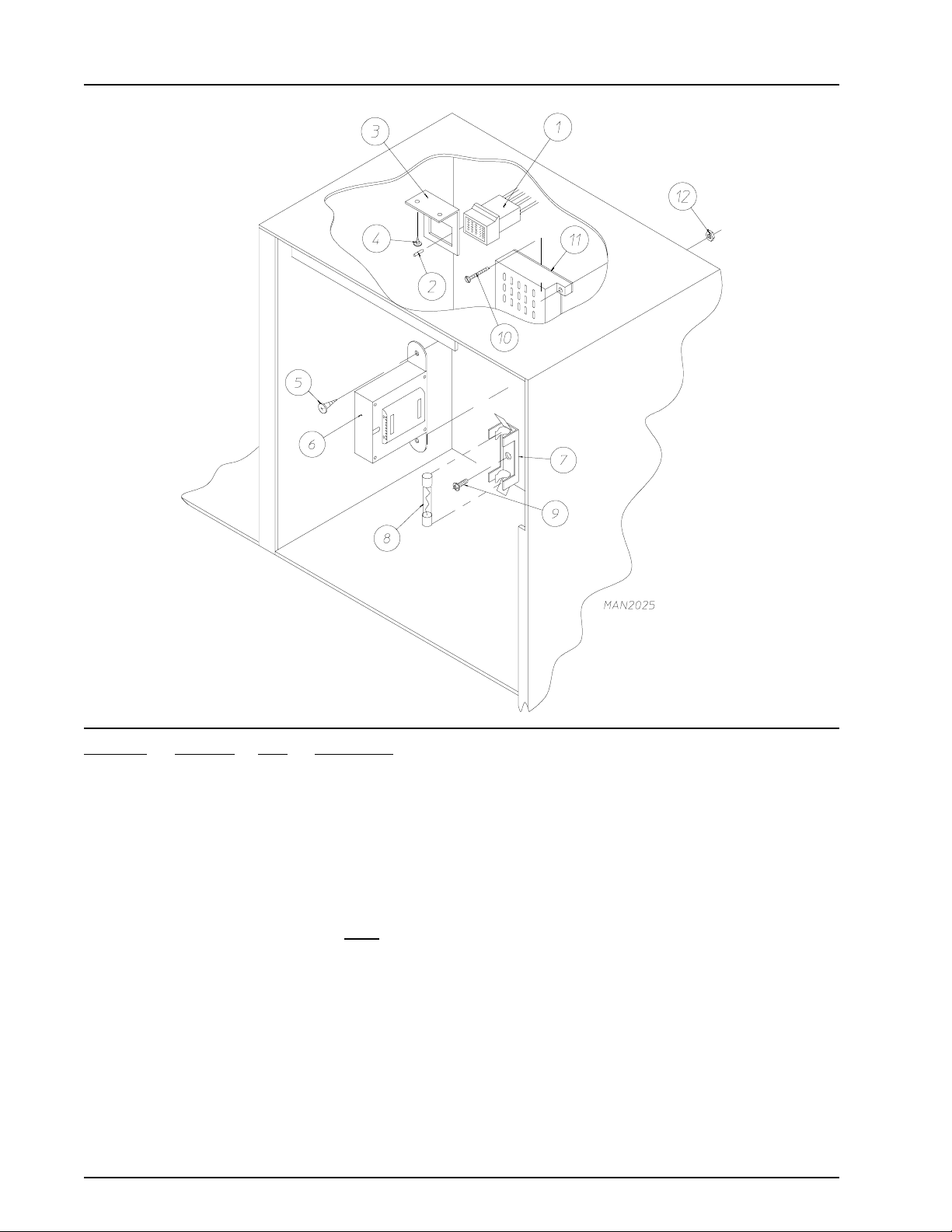
Page 6
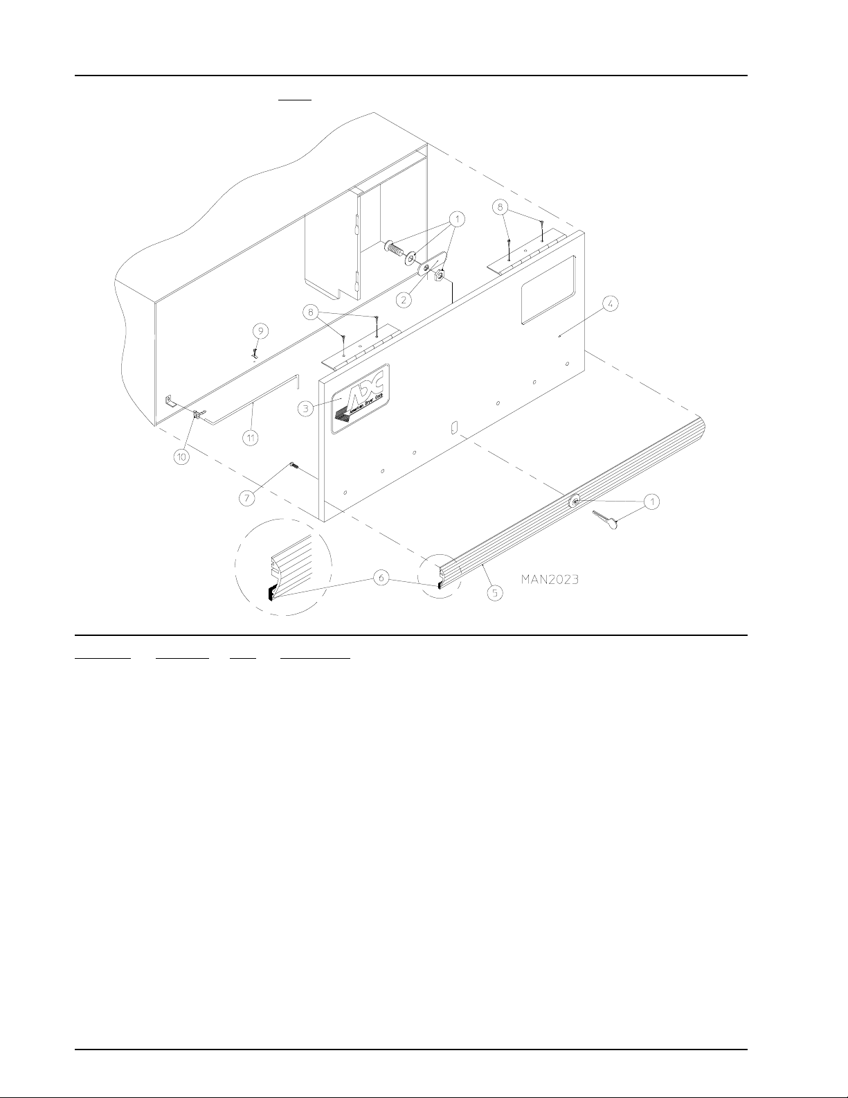
High Security Control Door Assembly
For ALL Coin Models and Non-Coin Models Mfd. prior to July 13, 1998
Illus. No. Part No. Qty. Description
1 160015 1 High Security MK-100 Lock Assembly with Key (for coin models Only)
160104 1 MK-100 Key Only
160017 1 Special Dummy Lock Only (for non-coin models Only)
2 160032 1 Lock Cam Only
3 881053 1 ADC Logo with Tape Kit
112350 1 ADC Logo Only
870011 1 Double Sided Tape Kit
4* 800022 1 High Security Control Door Assembly Less Lock
(includes illus. nos. 4 through 7)
800141 1 High Security Stainless Steel Control Door Assembly Less Lock
(includes illus. nos. 4 through 7)
5 180201 1 Top Trim with Lock Hole
6 117603 3 Suppressor Tape/Gasket (sold by the foot)
7 150201 5 #10-32 x 1/4” Phillips Round Head Machine Screw
8 150300 4 #10 x 1/2” Hex Washer TEK Screw
9 102603 1 Control Door Support Rod Catch
10 102601 1 Control Door Rod Retainer Clip
11 102502 1 Control Door Support Rod
* Specify color when ordering.
4 American Dryer Corporation 450302-5
Page 7
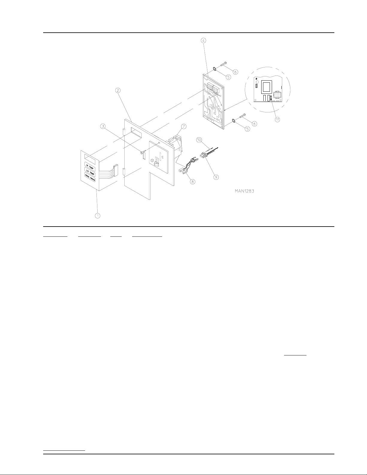
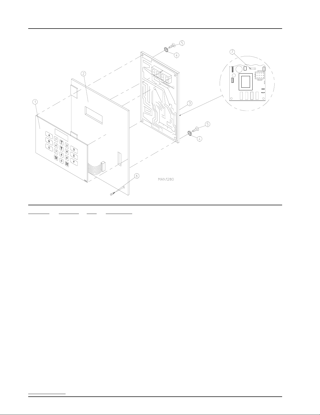
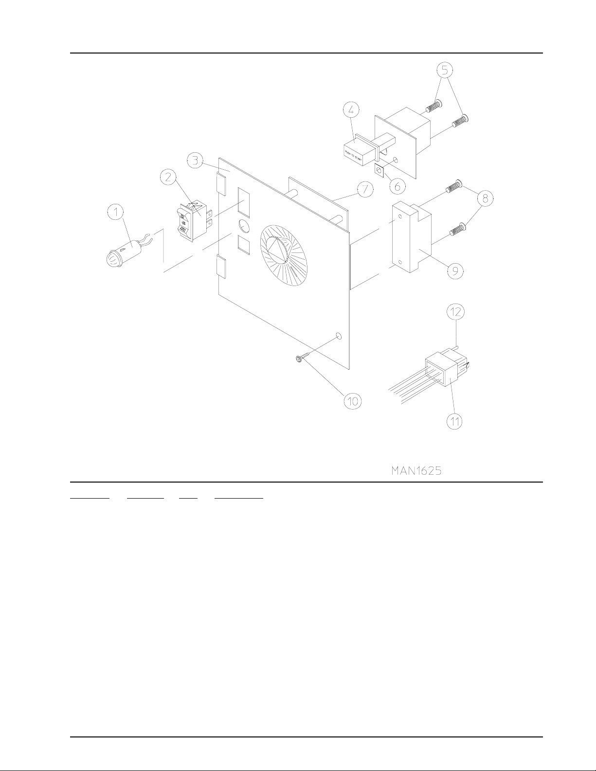
Phase 5 Coin Microprocessor Control Panel Assembly
Illus. No. Part No. Qty. Description
1 112526 1 Coin Keyboard Label Assembly
2 801213 1 Phase 5 Coin Control Panel Assembly
(includes illus. nos. 1, 2, 4 through 6 and 11)
801229 1 Phase 5 Coin Control Panel Assembly with Battery Option
(includes illus. nos. 1, 2, 4 through 6 and 11)
801259 1 Coin Control Panel Only
801258 1 Coin Control Panel with Battery Bracket
3 150309 1 #10-16 x 1/2” Hex Head TEK Crimptite Screw
4 137213 1 Phase 5 Coin Controller Only
824998 1 Phase 5 Battery Clip
5 153010 2 #6 Star Washer
6 150005 2 #6-32 x 1/4” Phillips Round Head Machine Screw
7 --------- 1 Microprocessor Coin Acceptor with Optical Switch
(refer to Microprocessor Coin Acceptors Listing on page 49)
8 137056 1* Optic Switch Only (Greenwald coin acceptors)
881143 1* Optic Switch Only (Hanke coin acceptors)
9 137023 1* Optic Switch Connector Only
10 137021 3* Microprocessor Socket Only
880772 1 Single Coin Optical Switch Harness
824080 1 Dual Coin Optical Switch Harness
122800 1 Microprocessor (female) Pin Extraction Tool
11 136048 1 1/8-Amp (Slo-Blo) Fuse
* For dual coin models, double the quantity.
IMPORTANT: Check label on computer chip to verify correct part number for controller.
450302-5 Telephone: (508) 678-9000 / www.amdry.com 5
Page 8
Phase 5 Non-Coin Microprocessor Control Panel Assembly
Illus. No. Part No. Qty. Description
1 112535 1 Non-Coin English Keyboard Label Assembly
112276 1 Non-Coin Stick-On Labels (English Only)...Not Illustrated
112275 1 3-Language Non-Coin Stick-On Labels...Not Illustrated
(Spanish, Italian, and Hebrew)
112277 1 3-Language Non-Coin Stick-On Labels...Not Illustrated
(English, Spanish, and Hebrew)
112278 1 5-Language Non-Coin Stick-On Labels...Not Illustrated
(Italian, Dutch, French, German, and Chinese)
2 801255 1 Phase 5 Microprocessor Control Panel Only
801256 1 Phase 5 Microprocessor Control Panel Only with Battery Bracket
801206 1 Phase 5 Non-Coin Non-Reversing Microprocessor Control Panel Assembly
Complete
(includes illus. nos. 1 through 7)
801207 1 Phase 5 Non-Coin Reversing Microprocessor Control Panel Assembly
Complete
(includes illus. nos. 1 through 7)
3 137222 1 Phase 5 Non-Coin Non-Reversing Controller Only
137231 1 Phase 5 Non-Coin Reversing Controller Only
824998 1 Phase 5 Battery Clip
4 153010 2 #6 Star Washer
5 150005 2 #6-32 x 3/4” Phillips Round Head Machine Screw
6 150309 1 #10-16 x 1/2” Hex Head TEK Crimptite Screw
7 136048 1 1/8-Amp (Slo-Blo) Fuse
IMPORTANT: Check label on computer chip to verify correct part number for controller.
6 American Dryer Corporation 450302-5
Page 9
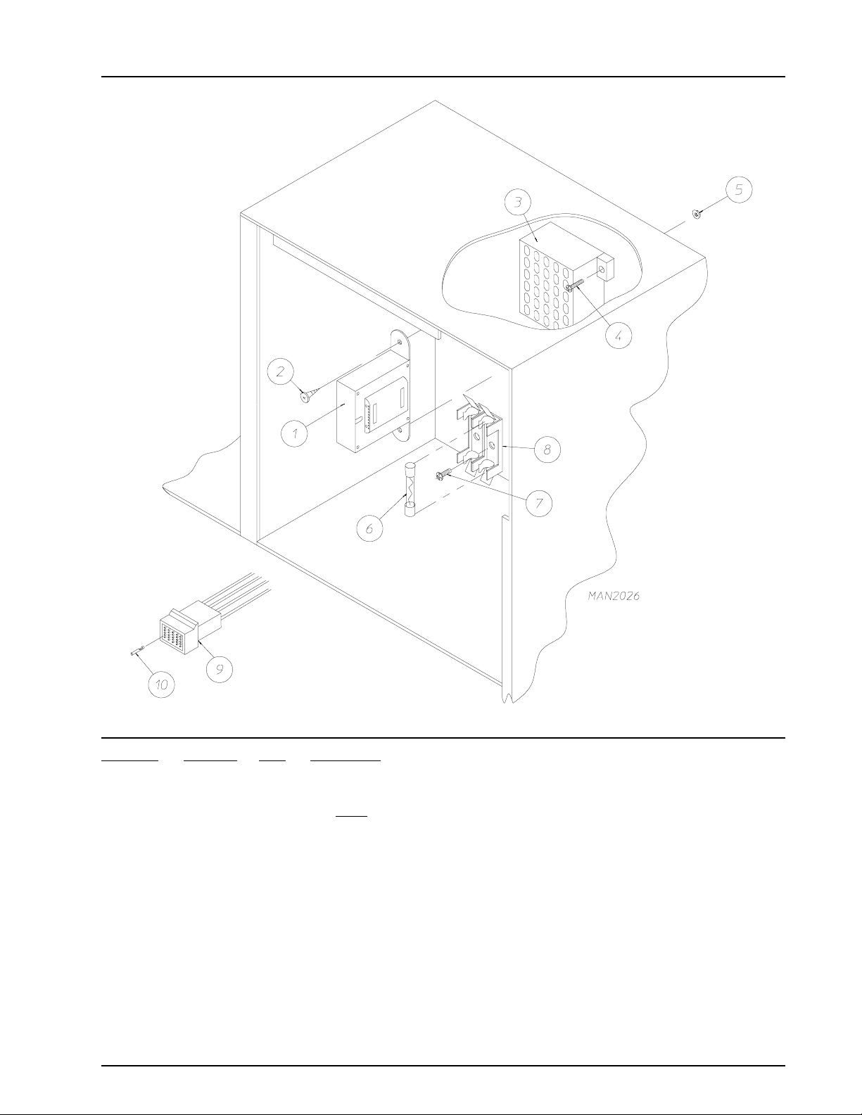
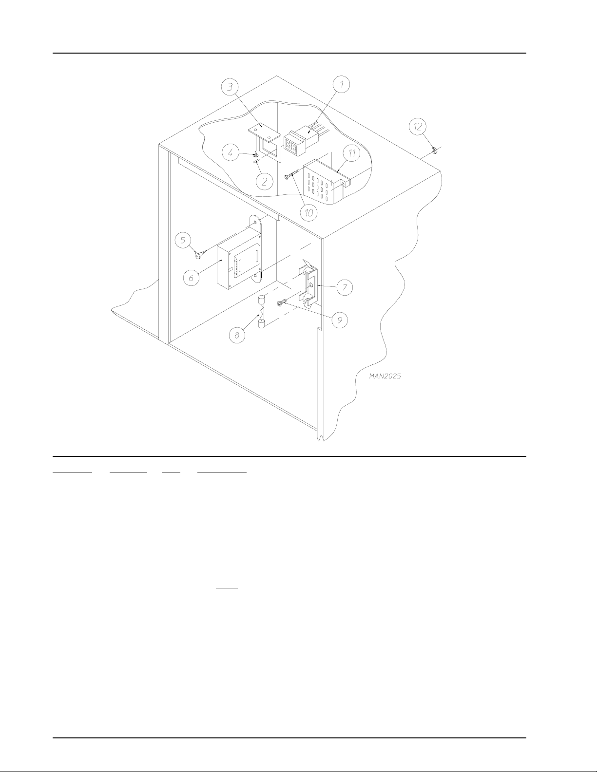
Phase 5 Coin and Non-Coin Microprocessor Control Box Assembly
Illus. No. Part No. Qty. Description
1 141403 1 24 VAC Transformer
For ALL Gas and Steam Models, and Electric Models of 380/416/480 Volt
132070 1 24 VAC Transformer
(for electric models of 208 volt/240 volt)
2 150300 2 #10 x 1/2” Hex Washer TEK Screw
3 120715 1 30-Position Terminal Block
4 150002 2 #6-32 x 1” Phillips Round Head Machine Screw
5 151000 2 #6-32 Pal Nut
6 136057 * 1/2-Amp (Slo-Blo) Fuse
7 150301 * #8-18 x 7/16” Phillips Pan Head TEK Screw
8 136008 * Fuse Block/Strip Only
9 122641 1 15-Pin Microprocessor Connector
10 122706 * Socket
* As required.
450302-5 Telephone: (508) 678-9000 / www.amdry.com 7
Page 10
Dual Timer “Tap Touch” Controls
For Models Mfd. as of November 3, 2000
Illus. No. Part No. Qty. Description
1 124030 1 15 Minute Timer - 24 VAC
2 124025 1 60 Minute Timer - 24 VAC
3 824175 1 Red Pilot Light - 24 VAC
4 122301 1 “Tap Touch” Switch
5 131932 3 Relay SPST 24v
6 120730 1 30-Position Terminal Block
7 151000 6 #6-32 Pal Nut
8 882903 1 Dual Timer Panel Complete
(includes illus. nos. 1 through 15)
850392 - Dual Timer Panel Only
9 153010 2 #6 Star Washer
10 152000 3 #6-32 Hex Nut
11 150207 2 #10-24 x 1/2” Phillips Pan Head Machine Screw
12 150110 4 #8-32 x 1/4” Phillips Round Head Machine Screw
13 112563 1 Dual Timer Panel Overlay
14 124104 1 Pure Touch Knob with Red Pointer
15 124105 1 Pure Touch Knob with Blue Pointer
8 American Dryer Corporation 450302-5
Page 11
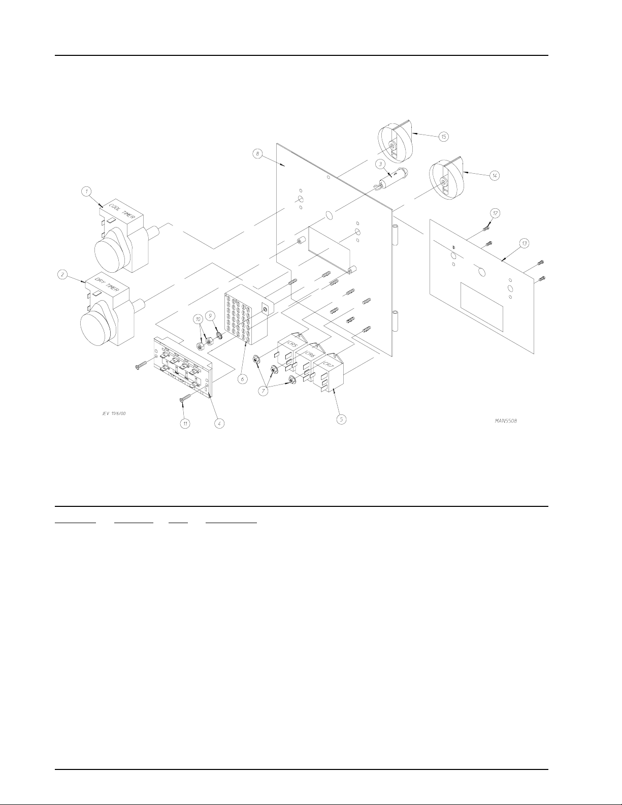
Dual Timer Control Panel Assembly
For Models Mfd. prior to November 3, 2000
Illus. No. Part No. Qty. Description
1 123005 1 Red Indicator Light - 24 VAC
2 122400 1 Rocker Heat Selector Switch
3 824015 1 Dual Timer Control Panel Assembly Complete - 24 VAC
(includes illus. nos. 1 through 21)
800051 1 Dual Timer Control Panel Only
4 131917 1 Push-to-Start Relay - 24 VAC
5 150207 2 #10-24 x 1/2” Round Head Machine Screw
6 154001 2 #10-24 Speed Nut
7 152000 2 #6-32 Hex Nut
8 153010 2 #6 Star Washer
9 120713 1 18-Position Terminal Block
10 150002 2 #6-32 x 1” Round Head Machine Screw
11 150110 4 #8-32 x 1/4” Phillips Machine Screw
12 150001 2 #6-32 x 1/2” Round Head Machine Screw
13 131931 1 Dual Timer Relay - 24 VAC
14 151000 2 #6-32 Pal Nut
15 112050 1 Dual Timer Label Only
16 150309 1 #10-16 x 1/2” Hex Head TEK Crimptite Screw
17 124103 2 Arrow Timer - 24 VAC
18 124025 1 60 Minute Timer - 24 VAC
19 124030 1 15 Minute Timer - 24 VAC
20 122602 1 9-Pin Connector Only
21 122700 8 Pin Terminal Only
-- 122801 1 Pin/Socket Extraction Tool
450302-5 Telephone: (508) 678-9000 / www.amdry.com 9
Page 12
Dual Timer Control Box Assembly
Illus. No. Part No. Qty. Description
1 122603 1 9-Pin Socket Connector
2 122701 9 Socket Terminal Only
122801 1 Pin/Socket Extraction Tool
3 315010 1 9-Pin Connector Bracket
4 150300 2 #10 x 1/2” Hex Washer TEK Screw
5 150300 2 #10 x 1/2” Hex Washer TEK Screw
6 141403 1 24 VAC Transformer
(for ALL gas and steam models, and electric models of 380/416/480 volt)
132070 1 24 VAC Transformer
(for electric models of 208 volt/240 volt)
7 136008 * Fuse Block/Strip Only
8** 136057 * 1/2-Amp (Slo-Blo) Fuse
9 150301 * #8 x 7/16” Phillips Pan Head TEK Screw
10 150002 2 #6-32 x 1” Phillips Round Head Machine Screw
11 120715 1 30-Position Terminal Block
12 151000 2 #6-32 Pal Nut
* As required.
** Check fusing on dryer for verification.
10 American Dryer Corporation 450302-5
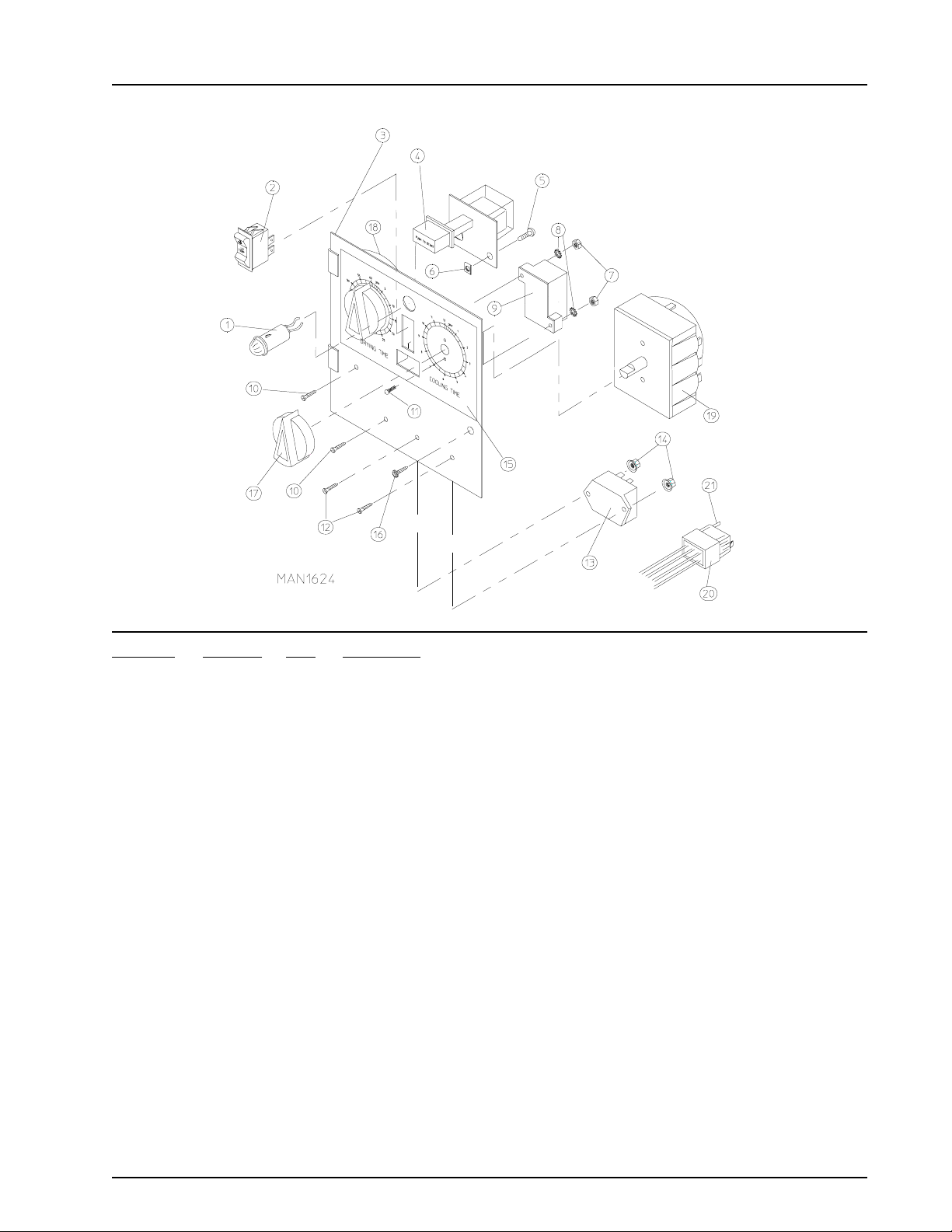
Page 13
Non-Microprocessor Coin Meter Control Panel Assembly
Illus. No. Part No. Qty. Description
1 123005 1 Red Indicator Light - 24 VAC
2 122400 1 Rocker Heat Selector Switch
3 824020 1 Coin Meter Control Panel Assembly Complete - 24 VAC
(includes illus. nos. 1 through 6 and 8 through 12)
800054 1 Coin Meter Control Panel Only
4 131917 1 Push-to-Start Relay - 24 VAC
5 150207 2 #10-24 x 1/2” Round Head Machine Screw
6 154001 2 #10-24 Speed Nut
7* 125601 1 25¢ Coin Meter 24v (specify timing)
8 150303 2 #4 x 3/4” Pan Head “A” Screw
9 120712 1 12-Position Terminal Block
10 150309 1 #10-16 x 1/2” Hex Head TEK Crimptite Screw
11 122602 1 9-Pin Connector Only
12 122700 9 Pin Terminal Only
-- 122801 1 Pin/Socket Extraction Tool
* Consult factory for coin meters not listed.
450302-5 Telephone: (508) 678-9000 / www.amdry.com 11
Page 14
Non-Microprocessor Coin Meter Control Box Assembly
Illus. No. Part No. Qty. Description
1 122603 1 9-Pin Socket Connector
2 122701 9 Socket Terminal Only
122801 1 Pin/Socket Extraction Tool
3 315010 1 9-Pin Connector Bracket
4 150300 2 #10 x 1/2” Hex Washer TEK Screw
5 150300 2 #10 x 1/2” Hex Washer TEK Screw
6 141403 1 24 VAC Transformer
(for ALL gas and steam models, and electric models of 380/416/480 volt)
132070 1 24 VAC Transformer
(for electric models of 208/240 volt)
7 136008 * Fuse Block/Strip Only
8** 136057 * 1/2-Amp (Slo-Blo) Fuse
9 150301 * #8 x 7/16” Phillips Pan Head TEK Screw
10 150002 2 #6-32 x 1” Phillips Round Head Machine Screw
11 120715 1 30-Position Terminal Block
12 151000 2 #6-32 Pal Nut
* As required.
** Check fusing on dryer for verification.
12 American Dryer Corporation 450302-5
Page 15
Coin Meter Replacement Parts
Illus. No. Part No. Qty. Description
1 125541 1 1/60 RPM 24v / 60 Hz Meter Motor
125540 1 1/30 RPM 24v / 50 Hz Meter Motor
2 125500 1 2-Point Cam
125501 1 3-Point Cam
125502 1 4-Point Cam
125503 1 5-Point Cam
125504 1 6-Point Cam
125506 1 8-Point Cam
125507 1 9-Point Cam
125508 1 10-Point Cam
125510 1 12-Point Cam
3 125515 1 Meter Switch “B” with Arm
4 125516 2 Meter Switch “A” or “C”
450302-5 Telephone: (508) 678-9000 / www.amdry.com 13
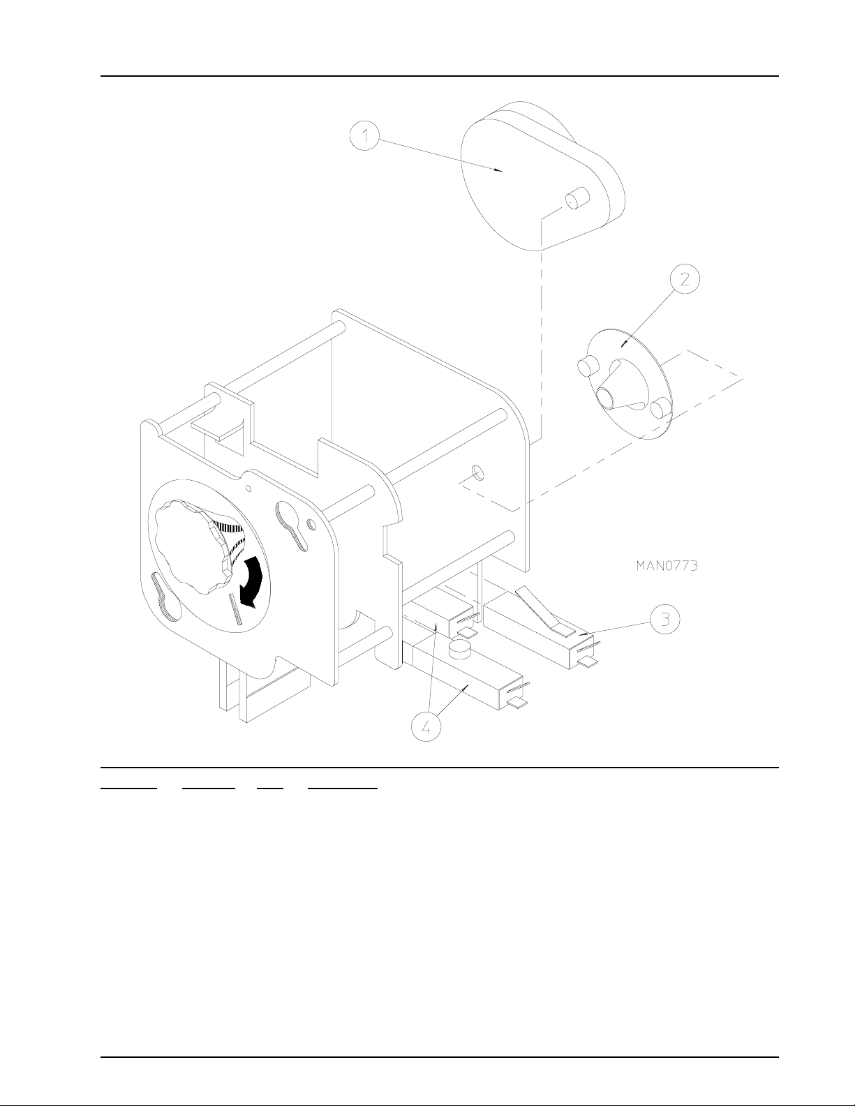
Page 16
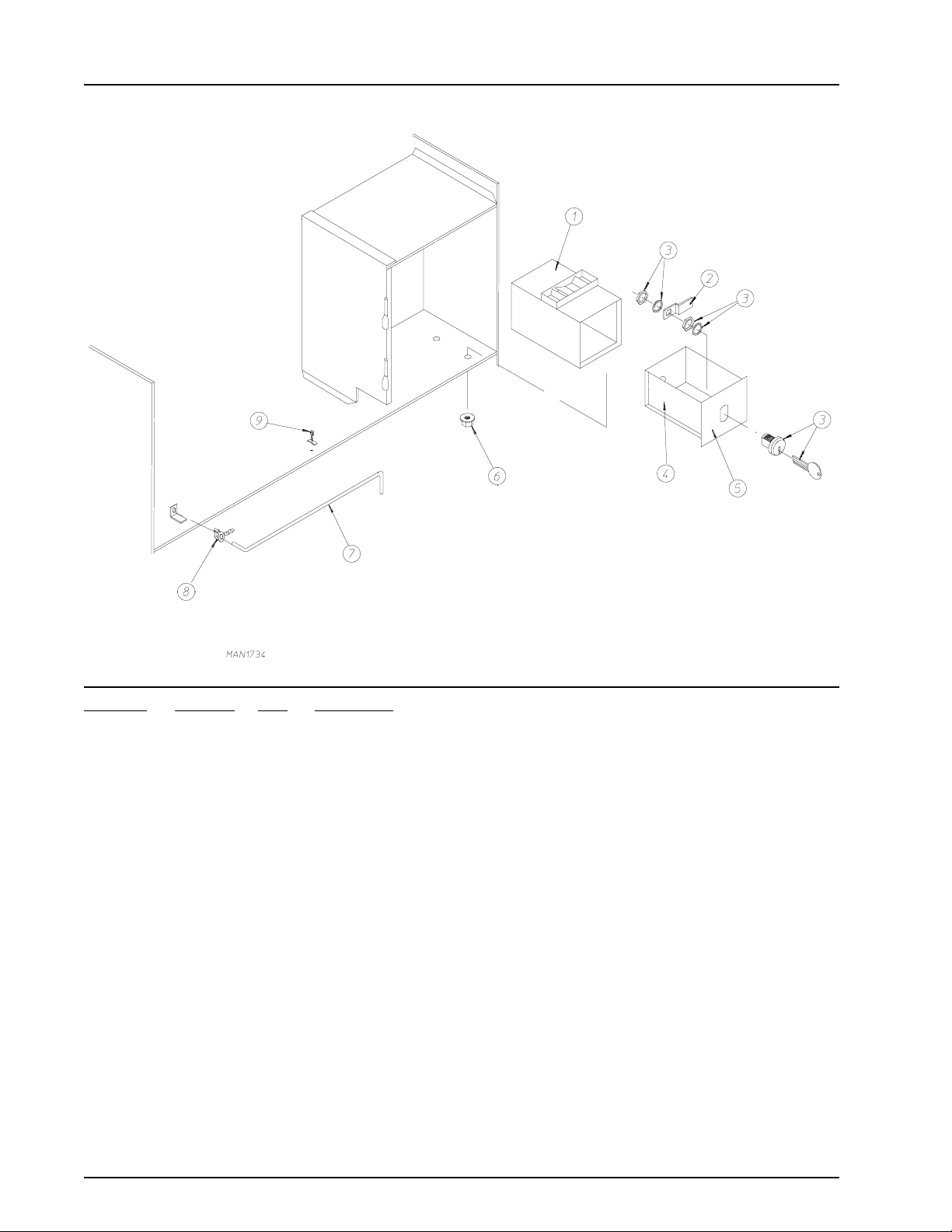
Coin Vault Assembly
Illus. No. Part No. Qty. Description
1 802112 1 Microprocessor Coin Vault Assembly Complete
(includes illus. nos. 1 through 6)
802117 1 Microprocessor Coin Vault Only
802110 1 Non-Microprocessor Coin Vault Assembly Complete
(includes illus. nos. 1 through 6)
802115 1 Non-Microprocessor Coin Vault Only
2 160006 1 Cam For 1/4 Turn Lock Only
3 875061 1 1/4 Turn Lock with Key and Cam
160105* 1 1/4 Turn Mer-Pel Key Only
4 802020 1 1/4 Turn Coin Box Assembly
(includes illus. nos. 2 through 5)
802019 1 1/4 Turn Coin Box Only without Face Plate
125915 1 High Security (Greenwald) Coin Box Only with Key
5 802018 1 1/4 Turn Coin Box Face Plate Assembly
(includes illus. nos. 2 through 5)
6 152014 4 1/4-20 Free Spin Wash Nut
7 102502 1 Control Door Support Rod
8 102601 1 Control Door Rod Retainer Clip
9 102603 1 Control Door Rod Catch
* Specify key number when ordering.
14 American Dryer Corporation 450302-5
Page 17
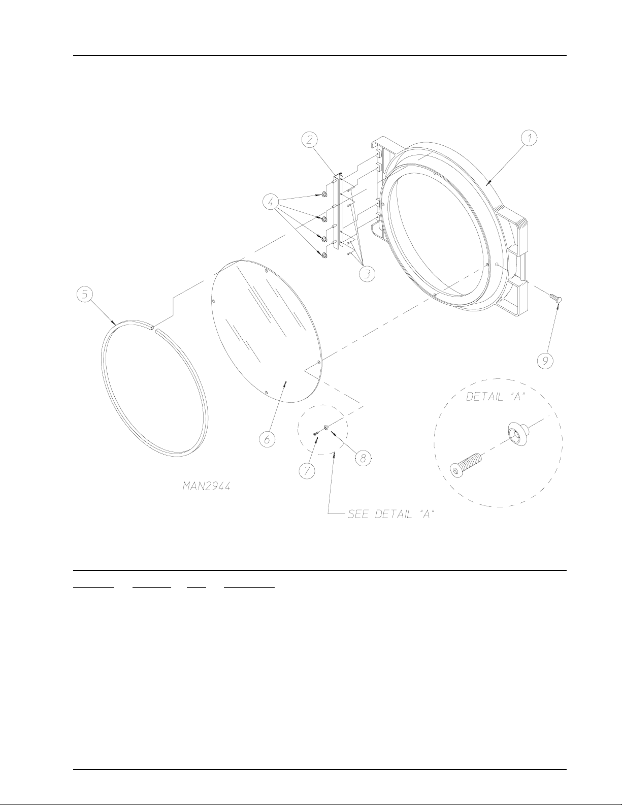
“Plastic” Main Door Assembly
Illus. No. Part No. Qty. Description
1 881421 1 Gray Plastic Main Door Assembly Complete with Mechanical Fasteners
(includes illus. nos. 1 and 5 through 9)
2 800448 4 12-1/2” Stainless Steel Main Door Hinge Assembly
3 150410 4 #10-24 x 3/8” Phillips Pan Head Taptite Screw
4 152014 1 1/4-20 Free Spin Wash Nut
5 102349 1 Main Door Gasket
6 102212 1 20-7/16” Door Glass with Four (4) Holes
170730 1 Main Door Glass Adhesive (10.3 oz. cartridge)
7 150448 4 1/2” Stainless Steel Flat Head Allen Screw
8 170319 4 Door Glass (Nylon) Spacer
9 150431 1 Main Door Latch Screw
(#10 x 7/16” dome hex head)
450302-5 Telephone: (508) 678-9000 / www.amdry.com 15
Page 18

Main Door Switch Assembly For “Plastic” Door
Illus. No. Part No. Qty. Description
1 152013 2 #6-32 Hex Nut
2 153008 2 #6 Lock Washer
3 137005 1 Single-Pole Door Switch
4 121028 2 Insulated Female Terminal
5 154281 2 3/8” Standard Nylon Spacers
6 800448 1 12-1/2” Stainless Steel Main Door Hinge Assembly
(includes illus. nos. 6 and 7)
7 153565 2 #6 Stud
8 313218 1 Main Door Switch Housing Only
9 150201 2 #10-32 x 1/4” Phillips Pan Head Screw
10 121405 1 Rubber Grommet
16 American Dryer Corporation 450302-5
Page 19

Front Panel Assembly For “Plastic” Door
Illus. No. Part No. Qty. Description
1 875301* 1 Insulated Front Panel Assembly Complete - Latch Type
(includes illus. nos. 1 through 3 and 5)
875312 1 Stainless Steel Right Hand Insulated Front Panel Assembly Complete -
Latch Type
(includes illus. nos. 1 through 3 and 5)
2 154215 2 1/8” Pop Rivet
3 170330 1 Friction Door Latch
4 150309 9 #10-16 x 1/2” Hex Head TEK Crimptite Screw
150313 9 #10-16 x 1/2” TORX Plus Type 1 Screw
(for models mfd. as of November 2, 2000)
150318 - TORX Plus Bit
5 121405 1 Rubber Grommet
* Specify color when ordering.
450302-5 Telephone: (508) 678-9000 / www.amdry.com 17
Page 20

Main Door “Steel” Assembly
Illus. No. Part No. Qty. Description
1 881150 1 Black Main Door Assembly Complete
(includes illus. nos. 1, 2, and 8 through 15)
2 102354 1 Door Gasket
170730 1 Clear Glass Adhesive (10.3 oz. cartridge)
170731 1 Black Glass Adhesive (10.3 oz. cartridge)
3 881152 1 Black Top Hinge Block Assembly
(includes illus. nos. 3 and 4)
4 150445 2 1/4-20 x 3/4” Black Cap Head Setscrew
5 153031 1 1/4” Nylon Washer
6 881151 1 Black Bottom Hinge Block Assembly
(includes illus. nos. 5, 6, and 7)
7 150445 2 1/4-20 x 3/4” Black Cap Head Setscrew
150443 2 1/4-20 x 3/4” Stainless Steel Cap Head Setscrew
8 150683 3 1/4-20 x 5/8” Black Carriage Bolt
9 152014 3 1/4-20 Free Spin Wash Nut
10 151010 1 #10-32 Black Hex Acorn Nut
11 150120 1 Door Latch Screw
12 150683 3 1/4-20 x 5/8” Black Carriage Bolt
13 152014 3 1/4-20 Free Spin Wash Nut
14 881210 1 Black Main Door Handle Only
15 102218 1 20-7/16” Door Glass
102360 1 Glass/Door Gasket Tape
(for models mfd. as of February 9, 2001)
170731 1 Black Glass Adhesive (10.3 oz. cartridge)
For Models Mfd. prior to February 9, 2001
16 151013 4 #10-32 Black Nylon Acorn Nut
18 American Dryer Corporation 450302-5
Page 21

Main Door Switch Assembly Cold Rolled Steel Door
Illus. No. Part No. Qty. Description
1 153566 2 #6-32 x 7/8” Clinch Stud
2 152013 2 #6-32 Hex Nut 1/4” ATF Zinc Plated
3 153010 2 #6 Star Washer
4 137005 1 Single-Pole Door Switch
5 122636 2 Flag Terminal
6 881211 1 Main Door Switch Housing
7 150301 2 #8-18 x 7/16” Phillips Pan Head TEK Screw
450302-5 Telephone: (508) 678-9000 / www.amdry.com 19
Page 22

Cold Rolled Steel Door Front Panel
Illus. No. Part No. Qty. Description
1 881270* 1 Right Hand Front Panel Assembly (cold rolled steel door)
(includes illus. nos. 1 through 3)
881288 1 Stainless Steel Front Panel Assembly (cold rolled steel door)
(includes illus. nos. 1 through 3)
881996* 1 Left Hand Front Panel Assembly (cold rolled steel door)
(includes illus. nos. 1 through 3)
2 154215 2 1/8” Pop Rivet
3 170330 1 Friction Door Latch
4 150300 1 #10-16 x 1/2” Hex Washer TEK Screw
5 150309 8 #10-16 x 1/2” Phillips Hex Head TEK Crimptite Screw
6 881152 1 Black Top Hinge Block Assembly
881208 1 Stainless Steel Top Hinge Block Assembly
7 150445 4 1/4-20 x 7/8” Black Cap Head Setscrew
150443 4 1/4-20 x 7/8” Stainless Steel Cap Head Setscrew
8 881151 1 Black Bottom Hinge Block Assembly
881209 1 Stainless Steel Bottom Hinge Assembly
* Specify color when ordering.
20 American Dryer Corporation 450302-5
Page 23

Lint Trap Assembly
Illus. No. Part No. Qty. Description
1 881064 1 Lint Trap Assembly Complete
(includes illus. nos. 1 and 3 through 5)
881063 1 Lint Trap Only
2 154200 7 5/32” Pop Rivet
3 150300 3 #10 x 1/2” Hex Washer TEK Screw
4 304100 1 Lint Screen Hold Down
5 800506 1 Lint Screen Only
6 150419 2 #6 x 1/2” Tamperproof TEK Screw
7 108120 1 Chain For Drop Lint Door
-- 150418 1 Tamperproof Screw Hand Driver
450302-5 Telephone: (508) 678-9000 / www.amdry.com 21
Page 24

Drop Lint Door Assembly Without Trim
For Non-Coin Models Mfd. as of July 13, 1998
Illus. No. Part No. Qty. Description
1 160001 1 AD-100 Lock Assembly with Key (for coin models Only)
160103 1 AD-100 Key Only
800150 1 Knob Latch Kit Assembly
(includes illus. nos. 1 and 2)
160003 1 Dummy Lock Only (for non-coin models)
160104 1 MK-100 Key Only (for dummy lock)
2 160008 1 Lock Cam For AD-100 and Dummy Lock
160009 1 Knob Latch Adjustable Cam Only
150425 1 #12-24 x 3/8” Round Head Machine Screw Only
(screw for knob latch adjustable cam)
3 157000 1 Drop Lint Door Spring
4 882264* 1 Insulated Drop Lint Door Assembly
(includes illus. nos. 4 through 8)
5 150201 6 #10-32 x 1/4” Phillips Pan Head TEK Screw
6 117604 7 Neoprene Sponge Tape (sold by the foot)
7 150419 2 #6 x 1/2” Tamperproof TEK Screw
8 108120 1 Chain For Drop Lint Door (10-1/2” length)
- 150418 1 Tamperproof Screw Hand Driver
* Specify color when ordering.
22 American Dryer Corporation 450302-5
Page 25

Drop Lint Door Assembly With Trim
For ALL Coin Models and Non-Coin Models Mfd. prior to July 13, 1998
Illus. No. Part No. Qty. Description
1 160001 1 AD-100 Lock Assembly with Key
160103 1 AD-100 Key Only
800150 1 Knob Latch Kit Assembly (for non-coin models)
(includes illus. nos. 1 and 2)
160200 1 Knob Latch Kit with Two (2) Screws (for non-coin models)
160003 1 Dummy Lock Only (for non-coin models)
160104 1 MK-100 Key Only
2 160008 1 Lock Cam For AD-100 Lock
160009 1 Knob Latch Adjustable Cam (for non-coin models)
150425 1 #12-24 x 3/8” Round Head Machine Screw
(for knob latch adjustable cam)
3 157000 1 Drop Lint Door Spring
4 800219* 1 Drop Lint Door Assembly
(includes illus. nos. 4 through 8)
800232* 1 Insulated Drop Lint Door Assembly
(includes illus. nos. 4 through 8)
800243 1 Stainless Steel Drop Lint Door Assembly
5 150201 10 #10-32 x 1/4” Phillips Pan Head Machine Screw
6 117600 7 Noise Suppressor Tape (sold by the foot)
7 117603 3 Suppressor Tape/Gasket (sold by the foot)
8 180211 2 Trim/Kick Plate (31-1/8” length)
9 150419 2 #6 x 1/2” Tamperproof Screw
150418 1 Tamperproof Screw Hand Driver
10 108120 1 Chain For Drop Lint Door
* Specify color when ordering.
450302-5 Telephone: (508) 678-9000 / www.amdry.com 23
Page 26

Tumbler/Support Assemblies
Illus. No. Part No. Qty. Description
1* 800838 1 Tumbler Only with Tapered Rib (without felt collar)
800837** 1 Non-Reversing Tumbler and Support Assembly with Tapered Rib
(includes illus. nos. 1 through 10)
800839** 1 Reversing Tumbler and Support Assembly with Tapered Rib
(includes illus. nos. 1 through 10)
2 150309 40 #10-16 x 1/2” Hex Head TEK Crimptite Screw
3 301302 2 Tumbler Rib Only (low rib)
301311 2 Tapered Tumbler Baffle Rib Only (high rib)
4 150500 1 5/16-18 x 3/8” Socket Button Head Screw
5 100903 4 5/16-18 x 38-1/2” Tie Rod
6 153004 4 3/8” Flat Washer
7 800616 1 Non-Reversing Tumbler Support Only
800614 1 Reversing Tumbler Support Only
8 152005 4 3/8-16 Hex Nut
9 153005 4 3/8” Lock Washer
10 153004 4 3/8” Flat Washer
11 116001 1 Felt Collar Only
--- 401010 1 #847 Adhesive For Felt Collar (5.0 oz. tube)
* For stainless steel tumbler, contact the factory.
** Felt collar is not included and must be ordered separately.
24 American Dryer Corporation 450302-5
Page 27

Idler Bearing Assembly
Illus. No. Part No. Qty. Description
1 100165 1 5L-610 V-Belt (idler to tumbler)
For Non-Reversing Models Only
100106 1 5L-690 V-Belt (idler to tumbler)
For Reversing Models Only
2 101140 1 14” x 3” Compound Pulley
3 100166 1 4L-790 V-Belt (idler to motor) 60 Hz
(for non-reversing models Only)
100167 1 4L-800 V-Belt (idler to motor) 50 Hz
(for non-reversing models Only)
100109 1 4L-650 V-Belt (idler to motor) 50/60 Hz
(for reversing models Only)
4 154301 2 5/16-18 x 1” Allen Setscrew
5 100705 1 3/16” x 3/16” x 1-3/8” Key
6 882576 1 Idler Bearing Assembly Complete
(includes illus. nos. 5 through 12)
7 150617 2 3/8-16 x 1” Hex Head Machine Bolt
8 153005 2 3/8” Lock Washer
9 153004 2 3/8” Flat Washer
10 801009 1 Idler Square Washer
11 152004 1 5/16-18 Hex Nut
12 150509 1 5/16-18 x 3” Hex Head Machine Bolt
450302-5 Telephone: (508) 678-9000 / www.amdry.com 25
Page 28

Tumbler Bearing Assembly
26 American Dryer Corporation 450302-5
Page 29

Tumbler Bearing Assembly
Illus. No. Part No. Qty. Description
1 880220 1 1-3/8” Flange Bearing Only
2 153005 4 3/8” Lock Washer
3 152005 4 3/8-16 Hex Nut
4 882544 1 Pillow Block Bearing Assembly Complete
(includes illus. nos. 4 through 14 and 20)
882545 1 Bearing Assembly Complete with Rotational Sensor
(includes illus. nos. 4 through 16 and 20)
882542 1 Bearing Support Only
882543 1 Bearing Support Only (with rotational sensor)
5 880202 1 1-3/8” Pillow Block Bearing Only
880779 1 1-3/8” Pillow Block Bearing Assembly (with rotational sensor)
6 150601 2 3/8-16 x 2” Hex Bolt
7 153004 8 3/8” Flat Washer
8 153005 2 3/8” Lock Washer
9 152005 2 3/8-16 Hex Nut
10 154326 2 5/16-24 x 3/8” Setscrew (black)
11 152004 4 5/16-18 Hex Nut
12 150621 2 5/16-18 x 1-1/2” Tap Bolt
13 153002 4 5/16” Lock Washer
14 150501 4 5/16-18 x 3/4” Tap Bolt
15 102120 1 Sintered 8 Magnet
401010 1 #847 Construction Mastic
16 824807 1 Rotational Sensor Assembly
17 100713 1 1/4” x 1/4” x 7/8” Key
18 101100 1 18” Pulley
19 100106 1 5L-690 V-Belt
20 150610 2 5/16-18 x 1-1/2” Allen Setscrew
450302-5 Telephone: (508) 678-9000 / www.amdry.com 27
Page 30

Non-Reversing Totally Enclosed, Fan-Cooled Motor Mount Assembly
Illus. No. Part No. Qty. Description
1 100166 1 4L-790 V-Belt (to idler assembly) 50/60 Hz Only
2 100701 1 3/16” x 3/16” x 1” Key
3 101130 1 5/8” x 2-1/2” Motor Pulley (60 Hz motors Only)
101139 1 5/8” x 2-3/4” Motor Pulley (50 Hz motors Only)
4 150501 4 5/16-18 x 3/4” Hex Head Machine Bolt
5 153002 4 5/16” Lock Washer
6 153001 4 5/16” Flat Washer
7 100073 1 1 hp 115-230v 1ø 60 Hz Non-Reversing Totally Enclosed, Fan-Cooled
Motor (plug type)
181016 1 3/4 hp 240v 1ø 50 Hz Non-Reversing Totally Enclosed, Fan-Cooled
Motor (plug type)
8 122701 8 Socket Terminal Only
122801 1 Pin/Socket Extraction Tool
9 137030 1 8-Pin Housing Connector
10 152004 4 5/16-18 Hex Nut
28 American Dryer Corporation 450302-5
Page 31

Non-Reversing Totally Enclosed, Fan-Cooled Motor Mount Assembly
Illus. No. Part No. Qty. Description
11 153002 4 5/16” Lock Washer
12 153001 4 5/16” Flat Washer
13 117600 4 Noise Suppressor Tape (sold by the foot)
14 154000 4 5/16-18 Tinnerman Nut
15 800919 1 1 hp Motor Mount Only (56Z frame)
(includes illus. no. 13)
803903 1 1 hp 115-230v 1ø 60 Hz Totally Enclosed, Fan-Cooled
Motor Mount Assembly Complete with Plug Motor
(includes illus. nos. 2 through 7 and 13 through 20)
881080 1 3/4 hp 240v 1ø 60 Hz Totally Enclosed, Fan-Cooled
Motor Mount Assembly Complete
(includes illus. nos. 2 through 7 and 13 through 20)
For Models Mfd. as of February 21, 1995
803904 1 3/4 hp 240v 1ø 50 Hz Totally Enclosed, Fan-Cooled
Motor Mount Assembly Complete
(includes illus. nos. 2 through 6 and 13 through 22)
For Models Mfd. prior to February 21, 1995
803905* 1 1 hp 208/230/380/460v 3ø 50 Hz Totally Enclosed, Fan-Cooled Motor
Mount Assembly Complete
(includes illus. nos. 2 through 6 and 13 through 22)
881065* 1 1 hp 208/230/380/460v 3ø 50 Hz Totally Enclosed, Fan-Cooled Motor
Mount Assembly Complete
(includes illus. nos. 2 through 6 and 13 through 22)
16 153050 2 1/2” S.A.E. Flat Washer
17 100603 1 16” Impellor with 3/4” Bore
18 100702 1 1/8” x 1/8” x 1-1/2” Key
19 153050 2 1/2” S.A.E. Flat Washer
20 152006 2 1/2-20 Left Hand Jam Nut
21 120200 1 3/8 x 90° Connector
22 100075 1 1 hp 208/230/380 460v 3ø 50/60 Hz Totally Enclosed, Fan-Cooled Motor
(56Z frame)
100076 1 3/4 hp 240v 1ø 50 Hz Totally Enclosed, Fan-Cooled Motor (56Z frame)
For Models Mfd. prior to February 21, 1995
* Specify voltage when ordering.
450302-5 Telephone: (508) 678-9000 / www.amdry.com 29
Page 32

Reversing Totally Enclosed, Fan-Cooled Motor Mount Assembly
30 American Dryer Corporation 450302-5
Page 33

Reversing Totally Enclosed, Fan-Cooled Motor Mount Assembly
Illus. No. Part No. Qty. Description
1 100109 1 4L-650 V-Belt (to idler assembly)
2 100701 1 3/16” x 3/16” x 1” Key
3 101130 1 5/8” x 2-1/2” Motor Pulley (60 Hz)
101139 1 5/8” x 2-3/4” Motor Pulley (50 Hz)
4 120200 1 3/8” x 90° Connector
5 181003 1 1/2 hp 208/230/380/460v 3ø 50/60 Hz Totally Enclosed, Fan-Cooled Motor
(56Z frame)
6 150501 4 5/16-18 x 3/4” Hex Head Machine Bolt
7 153002 4 5/16” Lock Washer
8 153001 4 5/16” Flat Washer
9 100075 1 1 hp 208/230/380/460v 3ø 50/60 Hz Totally Enclosed, Fan-Cooled Motor
(56Z frame)
10 120200 1 3/8” x 90° Connector
11 150501 4 5/16-18 x 3/4” Hex Head Machine Bolt
12 153002 4 5/16” Lock Washer
13 153001 4 5/16” Flat Washer
14 154000 8 5/16” Tinnerman
15 152004 4 5/16”-18 Hex Nut
16 153002 4 5/16” Lock Washer
17 153001 4 5/16” Flat Washer
18 800920 1 Reversing Motor Mount Only (56Z frame)
(includes illus. no. 19)
881067* 1 Reversing Totally Enclosed, Fan-Cooled Motor Mount Assembly Complete
(includes illus. nos. 2 through 14 and 18 through 24)
For 60 Hz Models Only
881066* 1 Reversing Totally Enclosed, Fan-Cooled Motor Mount Assembly Complete
(includes illus. nos. 2 through 14 and 18 through 24)
For 50 Hz Models Only
19 117600 5 Noise Suppressor Tape (sold by the foot)
20 153050 2 1/2” S.A.E. Flat Washer
21 100702 1 1/8” x 1/8” x 1-1/2” Key
22 100603 1 16” Impellor with 3/4” Bore
23 153050 2 1/2” S.A.E. Flat Washer
24 152006 2 1/2-20 Left Hand Jam Nut
* Specify voltage when ordering.
450302-5 Telephone: (508) 678-9000 / www.amdry.com 31
Page 34

Sensor Bracket Assemblies
32 American Dryer Corporation 450302-5
Page 35

Sensor Bracket Assemblies
Illus. No. Part No. Qty. Description
1 880251 1 1/4” Temperature Sensor Probe Assembly
(includes illus. nos. 1 and 5 through 8)
2 130103 1 225° Large Automatic Thermostat
130301 1 225° Manual Reset Thermostat
3 153010 2 #6 Star Washer
4 152000 2 #6-32 Hex Nut
5 121028 2 Insulated Terminal Only
6 122701 4 Socket Terminal Only
7 122605 1 4-Pin Socket Connector Only
8 154007 2 1/4” Tinnerman Push On Fastener
9 150005 2 #6-32 x 1/4” Round Head Machine Screw
10 801425 1 Microprocessor Sensor Bracket Assembly Complete
(includes illus. nos. 1 through 10)
305007 1 Universal Sensor Bracket Only
11 122604 1 4-Pin Connector Only
12 122700 4 Pin Terminal Only
13 150301 2 #8-18 x 7/16” Phillips Pan Head TEK Screw
14 150005 5 #6-32 x 1/4” Round Head Machine Screw
15 130111 1 130° Large Thermostat
16 130100 1 150° Large Thermostat
17 130103 1 225° Large Automatic Reset Thermostat
130301 1 225° Manual Reset Thermostat
18 130101 1 180° Large Thermostat
19 153010 5 #6 Star Washer
20 152000 5 #6-32 Hex Nut
21 840065 1 Sensor Jumper (4)
22 121028 8 Insulated Terminal Only
23 122701 4 Socket Terminal Only
24 122605 1 4-Pin Socket Connector Only
831702 1 Sensor (4) Bracket Harness Assembly
(includes illus. nos. 22 through 24)
25 801418 1 Non-Computer Sensor (4) Bracket Assembly Complete
(includes thermostats)
(includes illus. nos. 14 through 25)
305007 1 Universal Sensor Bracket Only
26 122604 1 4-Pin Connector Only
27 122700 4 Pin Terminal Only
122801 1 Pin/Socket Extraction Tool
28 150301 2 #8-18 x 7/16” Phillips Pan Head TEK Screw
450302-5 Telephone: (508) 678-9000 / www.amdry.com 33
Page 36

Direct Spark Ignition Burner Assembly
34 American Dryer Corporation 450302-5
Page 37

Direct Spark Ignition Burner Assembly
Illus. No. Part No. Qty. Description
1 318030 1 Direct Spark Ignition Burner Shield
2 150300 2 #10 x 1/2” Hex Washer TEK Screw
3 150309 2 #10-16 x 1/2” Hex Head TEK Crimptite Screw
4 128915 1 Direct Spark Ignition Ignitor/Flame Probe Assembly
880134 1 Ignitor/Flame Probe Kit Assembly
(includes illus. nos. 4 and 5)
5 880330 1 High Voltage Wire and Connector Assembly
6 150103 3 #8-32 x 1/2” Pan Head Machine Screw
7 153000 3 #8 Steel Burr
8 151001 3 #8-32 Pal Nut
9 141105 3 Large Tube Burner
10* 140856 3 #23 Natural Gas Burner Orifice (60 Hz Only)
140810 3 #42 Liquid Propane Gas Burner Orifice (60 Hz Only)
140821 3 #28 Natural Gas Burner Orifice (50 Hz Only)
140808 3 #44 Liquid Propane Gas Burner Orifice (50 Hz Only)
11 141232 1 1/2” Direct Spark Ignition Manifold (3-Port)
12 318700 2 Pipe Bracket (bent)
13 150300 4 #10 x 1/2” Hex Washer TEK Screw
14 128927 1 1/2” 24 VAC Redundant (natural gas) Gas Valve
880960 1 1/2” 24 VAC Redundant (liquid propane gas) Gas Valve
140411 1 1/2” Valve Conversion Kit (liquid propane gas)
15 318712 1 GV Pipe Bracket
(for models mfd. as of August 10, 1995)
16 150309 2 #10-16 x 1/2” Phillips Round Head Crimptite
(for models mfd. as of August 10, 1995)
17 881367 1 1/2” Union Shut Off with Tail Piece
18 142809 1 1/2” x 29-1/8” Pipe
19 150299 2 #10 x 1” Hex Washer TEK Screw
20 128935 1 Johnson Controls Direct Spark Ignition Module (blue)
For Models Mfd. as of April 15, 2000
880815 1 ADC Direct Spark Ignition Module Only (50/60 Hz) (white)
21 850899 1 Non-Heat Reclaimer Burner Box Only
--- 809627** 1 Natural Gas Burner Assembly Complete Less Orifices
--- 809628** 1 Liquid Propane Gas Burner Assembly Complete Less Orifices
--- 880984* 1 Super AD-50 Liquid Propane Conversion Kit (60 Hz models)
--- 880985* 1 Super AD-50 Liquid Propane Conversion Kit (50 Hz models)
* Consult factory for elevations over 2,000 feet.
** Orifices are not included and must be ordered separately.
450302-5 Telephone: (508) 678-9000 / www.amdry.com 35
Page 38

Electric Oven Assembly
36 American Dryer Corporation 450302-5
Page 39

Electric Oven Assembly
Illus. No. Part No. Qty. Description
1 803007* 1 Large Electric Oven Box Only
--------* 1 Electric Oven Assembly Complete
2 --------* - Electric Element
3 150300 2 #10 x 1/2” Hex Washer TEK Screw
4 802800 1 Sail Switch Box with Cover and Bracket Only
802801 1 Sail Switch Box Assembly Complete
(includes illus. nos. 4 through 12)
5 154004 1 Twin Speed Nut
6 150309 2 #10-16 x 1/2” Hex Head TEK Crimptite Screw
7 802799 1 Sail Switch Box Cover Only
8 122200 1 Sail Switch
9 150303 2 #4 x 3/4” Pan Head “A” Machine Screw
10 105500 1 Sail Switch Actuator Rod
11 319202 1 Sail Switch Damper (flat)
12 154002 1 1/8” Push On Fastener
13 150300 2 #10 x 1/2” Hex Washer TEK Screw
14 803100 1 Electric Oven Front Cover Only
15 320611 1 Large Relay Box Cover Only
16 150402 2 #10-24 x 5/8” Slotted Truss Head Machine Screw
17 130400 1 290° Hi-Limit
18 150300 2 #10 x 1/2” Hex Washer TEK Screw
19 154001 1 #10-24 Speed Nut
20 121010 1 L-70 Ground Lug
21 152014 3 1/4”-20 Free Spin Wash Nut
22 --------* 1 Oven Relay
23 --------* 1 Oven Relay Replacement Coil
24 120081 - Internal Ceramic Insulator (2 per element)
25 120080 - External Ceramic Insulator (2 per element)
26 152008 - #10-32 Hex Nut (4 per element)
27 121011* - Bus Bar (sold by the foot)
28 --------* - Terminal Lug
29 153009 - #10 Star Washer (2 per element)
30 320607 1 Large Electric Oven Right Side Cover Only
31 150402 2 #10-24 x 5/8” Slotted Truss Head Machine Screw
* Refer to Electric Oven Chart on page 46.
450302-5 Telephone: (508) 678-9000 / www.amdry.com 37
Page 40

Steam Coil/Air Operated Steam Damper Assembly
38 American Dryer Corporation 450302-5
Page 41

Steam Coil/Air Operated Steam Damper Assembly
Illus. No. Part No. Qty. Description
1 165009 1 Steam Coil Assembly
2 153002 6 5/16” Lock Washer
3 152004 6 5/16-18 Hex Nut
4 152002 4 1/4-20 Hex Nut
5 153007 4 1/4” Lock Washer
6 820321 2 Steam Damper Hinge Assembly
7 803415 1 Steam Damper Assembly
(includes illus. nos. 7, 10, and 11)
8 153007 4 1/4” Lock Washer
9 152002 4 1/4-20 Hex Nut
10 115995 60 Steam Damper Gasket (sold by the inch)
11 102350 1 68-1/2” Long Steam Damper Foam Gasket
12 151007 1 7/16-20 Stainless Steel Acorn Nut
13 152007 1 7/16-20 Hex Nut
14 100497 1 1-1/4” x 3” Stroke Piston
15 100492 1 Piston Support Bracket
16 152002 2 1/4-20 Hex Nut
17 153007 2 1/4” Lock Washer
18 100472 1 1/4” Poly x 1/8” M.P.T. Connector
19 143110 1 1/4” Poly Flo Tubing (sold by the foot)
20 100472 1 1/4” Poly x 1/8” M.P.T. Connector
21 100496 1 1/8” Needle Valve
22 143238 1 1/8” Brass Close Nipple
23 100498 1 3-Way Micro Valve 24 VAC
24 150002 2 #6-32 x 1” Machine Bolt
25 153010 2 #6 Star Washer
26 152000 2 #6-32 Hex Nut
27 330987 1 Micro Valve Support
28 152002 2 1/4-20 Hex Nut
29 153007 2 1/4” Lock Washer
30 100520 1 1/8” N.P.T. Silencer (muffler)
450302-5 Telephone: (508) 678-9000 / www.amdry.com 39
Page 42

Sail Switch/Hi-Limit Assembly
Illus. No. Part No. Qty. Description
1 154004 1 Twin Speed Nut
2 150309 2 #10-16 x 1/2” Hex Head TEK Crimptite Screw
3 802799 1 Sail Switch Box Cover and Bracket Only
4 150303 2 #4 x 3/4” Pan Head “A” Machine Screw
5 122200 1 Sail Switch Only
6 105500 1 Sail Switch Actuator Rod
7 319202 1 Sail Switch Damper (flat)
8 154002 1 1/8” Push On Fastener
9 802800 1 Sail Switch Box with Cover and Bracket Only
802801 1 Sail Switch Assembly Complete
(includes illus. nos. 1 through 8)
10 142809 1 1/2” x 29-1/8” Pipe
11 150309 2 #10-16 x 1/2” Round Head Machine Screw
12 319704 1 Hi-Limit Mounting Bracket Only
13 151000 2 #6-32 Pal Nut
14 151001 2 #6-32 x 1/2” Round Head Machine Screw
15 130403 1 330° Hi-Limit (automatic reset)
130201 1 330° Hi-Limit (manual reset)
16 143000 1 1/2” x 3/4” Reducing Coupling
40 American Dryer Corporation 450302-5
Page 43

Single-Phase (1Ø) Motor, Electric Relay Panel Assembly
Illus. No. Part No. Qty. Description
1 132475 1 2-Pole Contactor 24 VAC
2 150299 2 #10 x 1” Hex Head Screw
3 824828 1 RC Network with Connectors
(for microprocessor controlled models Only)
- 322809 1 Back Electrical Box Cover...Not Illustrated
- 150301 4 #8-18 x 7/16” Phillips Pan Head TEK Screw...Not Illustrated
450302-5 Telephone: (508) 678-9000 / www.amdry.com 41
Page 44

3-Phase (3Ø) Motor, Electric Relay Panel Assembly
Illus. No. Part No. Qty. Description
1 322812 1 Back Electrical Box Component Plate
2 132430 1 Impellor Contactor (208/230/240v, 50/60 Hz) 24v Coil
3 150103 2 #8-32 x 3/4” Phillips Round Head Machine Screw
4 151001 2 #8-32 Pal Nut
5 153002 1 5/16-18 Lock Washer
6 152004 1 5/16-18 Hex Nut
7 120701 1 4-Position Terminal Block
8 150008 2 #6-32 x 1-1/4” Slotted Round Head Machine Screw
9 151000 2 #6-32 Pal Nut
10 121300 3 Open/Closed Bushing
11 137015 1 RC Filter (for microprocessor controlled models Only)
12 150300 2 #10 x 1/2” Hex Washer TEK Screw
13 --------- - Transformer
(refer to Transformer Listings on page 47 and page 48)
-- 322809 1 Back Electrical Box Cover...Not Illustrated
-- 150301 4 #8-18 x 7/16” Phillips Pan Head TEK Screw...Not Illustrated
42 American Dryer Corporation 450302-5
Page 45

Microprocessor Reversing Rear Control Box Assembly
Illus. No. Part No. Qty. Description
1 322812 1 Back Electrical Box Component Plate
2 137060 1 Arc Suppressor Board
3 137013 4 Nylon Standoff
4 882386 1 Reversing Contactor (208/230/240v, 50/60 Hz) 24v Coil
5 150103 2 #8-32 x 3/4” Phillips Round Head Machine Screw
6 151001 2 #8-32 Pal Nut
7 153002 1 5/16-18 Lock Washer
8 152004 1 5/16-18 Hex Nut
9 132430 1 Impellor Contactor (208/230/240v, 50/60 Hz) 24v Coil
10 150103 2 #8-32 x 3/4” Phillips Round Head Machine Screw
11 151001 2 #8-32 Pal Nut
12 120701 1 4-Position Terminal Block
13 150008 2 #6-32 x 1-1/4” Slotted Round Head Machine Screw
14 151000 2 #6-32 Pal Nut
15 121300 3 Open/Closed Bushing
16 150300 2 #10 x 1/2” Hex Washer TEK Screw
17 --------- - Transformer
(refer to Transformer Listings on page 47 and page 48)
-- 322809 1 Back Electrical Box Cover...Not Illustrated
-- 150301 4 #8-18 x 7/16” Phillips Pan Head TEK Screw...Not Illustrated
450302-5 Telephone: (508) 678-9000 / www.amdry.com 43
Page 46

Dual Timer Reversing Rear Control Box Assembly
Illus. No. Part No. Qty. Description
1 322812 1 Back Electrical Box Component Plate
2 132198 1 Reversing Timer 24v 50/60 Hz
3 150301 2 #8-18 x 7/16” Phillips Pan Head TEK Screw
4 882386 1 Reversing Contactor (208/230/240v, 50/60 Hz) 24v Coil
5 150103 2 #8-32 x 3/4” Phillips Round Head Machine Screw
6 151001 2 #8-32 Pal Nut
7 153002 1 5/16-18 Lock Washer
8 152004 1 5/16-18 Hex Nut
9 132430 1 Impellor Contactor (208/230/240v, 50/60 Hz) 24v Coil
10 150103 2 #8-32 x 3/4” Phillips Round Head Machine Screw
11 151001 2 #8-32 Pal Nut
12 120701 1 4-Position Terminal Block
13 150008 2 #6-32 x 1-1/4” Slotted Round Head Machine Screw
14 151000 2 #6-32 Pal Nut
15 121300 3 Open/Closed Bushing
16 150300 2 #10 x 1/2” Hex Washer TEK Screw
17 --------- - Transformer
(refer to Transformer Listings on page 47 and page 48)
-- 322809 1 Back Electrical Box Cover...Not Illustrated
-- 150301 4 #8-18 x 7/16” Phillips Pan Head TEK Screw...Not Illustrated
44 American Dryer Corporation 450302-5
Page 47

Outer Top/Back Guard Assemblies
Illus. No. Part No. Qty. Description
1 322809 1 Back Electrical Box Cover
2 150301 4 #8-18 x 7/16” Phillips Pan Head TEK Screw
3 314421 1 Top Back Guard (gas models Only)
(for models mfd. as of April 20, 1998)
314422 1 Top Back Guard (electric models Only)
(for models mfd. as of April 20, 1998)
314411 1 Top Back Guard
(for models mfd. prior to April 20, 1998)
No Top Back Guard on Steam Models
4 150301 7 #8-18 x 7/16” Phillips Pan Head TEK Screw
5 150301 10 #8-18 x 7/16” Phillips Pan Head TEK Screw
6 801577 1 Outer Top (electric models Only)
312533 1 Outer Top (gas models Only)
No Outer Top on Steam Models
7 314523 1 Bottom Back Guard (plain)
8 150301 13 #8-18 x 7/16” Phillips Pan Head TEK Screw
9 103500 4 Leveling Legs
450302-5 Telephone: (508) 678-9000 / www.amdry.com 45
Page 48

Electric Oven Chart
Element Oven Wire Terminal Lug Bus Bar Oven Relay
SUPER AD-50
Qty. Kw Part # Qty. Size Part # Qty. Part # 121011 Cat # Part #
48 208 3Ø 3 or 4 881624 6 8 120051 5 #4 133300 6 121010 1 DPA63 131369
48 240 3Ø 3 -- -- -- -- -- -- -- -- -- -- -- --
483803Ø3 or 4 -- ---------------- -- -- --
484163Ø3 or 4 -- ---------------- -- -- --
48460/4803Ø3 or 4 -- ---------------- -- -- --
Kw Volt Phase Wire Oven Assy.
42 208 3Ø 3 or 4 881629 6 7 120034 5 #6 133200 6 121010 1 DPA63 131369
42 240 3Ø 3 881630 6 7 120035 5 #2 133302 5 121012 1 GEAJ 131385
423803Ø3 or 4 -- ---------------- -- -- --
424163Ø3 or 4 -- ---------------- -- -- --
42460/4803Ø3 or 4 -- ---------------- -- -- --
402083Ø3 or 4 -- ---------------- -- -- --
40 240 3Ø 3 -- -- -- -- -- -- -- -- -- -- -- --
403803Ø3 or 4 -- ---------------- -- -- --
40 416 3Ø 3 or 4 824922 6 6.6 120027 4 #6 133200 6 121010 1 DFAJ 131361
36 208 3Ø 3 or 4 824921 6 6 120015 4 #2 133302 8 121012 1 GEAJ 131385
40460/4803Ø3 or 4 -- ---------------- -- -- --
36 240 3Ø 3 824920 6 6 120014 4 #2 133302 6 121010 1 FEAJ 131375
363803Ø3 or 4 -- ---------------- -- -- --
36 416 3Ø 3 or 4 824921 6 6 120015 4 #2 133302 3 121012 1 DFAJ 131361
36 460/480 3Ø 3 or 4 824920 6 6 120014 4 #2 133302 6 121010 1 CEAJ 131357
30 208 3Ø 3 or 4 824917 6 5 120012 3 #4 133300 5 121012 1 DPA43 131357
30 240 3Ø 3 824934 6 5 120013 3 #4 133300 5 121012 1 EEAJ 131369
30 380 3Ø 3 or 4 824976 6 5 120000 4 #8 133100 6 121010 2 FEAJ 131375
30 416 3Ø 3 or 4 824949 6 5 120012 4 #8 133100 6 121010 2 DPA43 131357
30 480 3Ø 3 or 4 824955 6 5 120013 4 #8 133100 6 121010 2 DPA43 131357
44 460 3Ø 3 824003 8 6 120052 4 #2 133302 6 121010 1 DEAJ 131352
NOTE: Information not listed was not available at time of printing contact factory.
46 American Dryer Corporation 450302-5
Page 49

Transformer Listing Gas/Steam Dryers
egatloVlortnoC
.oNtraP
.oNtraPremrofsnarT
nwodpetS
05-DArepuS
eriW
ecivreS
042-8024ro3---304141
0833 950231304141
0834 950231304141
6143 260231304141
6144 260231304141
084/0643 350231304141
084/0644 350231304141
5753 050231304141
maetS
taeHegatloV
saG
450302-5 Telephone: (508) 678-9000 / www.amdry.com 47
Page 50

Transformer Usage Listing For Electric Dryers
SUPER AD-50
Kw Volt Phase Wire
48 208 3Ø 3 or 4 -- 132070
48 240 3 Ø 3 -- 132070
48 380 3 Ø 3 or 4 132059 132070
48 416 3 Ø 3 or 4 132062 132070
48 460/480 3Ø 3 or 4 132053 132070
42 208 3Ø 3 or 4 -- --
42 240 3Ø 3 -- --
42 380 3Ø 3 or 4 -- --
42 416 3Ø 3 or 4 -- --
42 460/480 3Ø 3 or 4 -- --
40 208 3Ø 3 or 4 -- --
Stepdown Transformer
Part No.
Control Voltage Transformer
Part No.
40 240 3Ø 3 -- --
40 380 3 Ø 3 or 4 132059 141403
40 416 3 Ø 3 or 4 132062 141403
40 460/480 3Ø 3 or 4 132053 141403
36 208 3Ø 3 or 4 -- 132070
36 240 3 Ø 3 -- 132070
36 380 3 Ø 3 or 4 132059 141403
36 416 3 Ø 3 or 4 132062 141403
36 460/480 3Ø 3 or 4 132053 141403
30 208 3Ø 3 or 4 -- 132070
30 240 3 Ø 3 -- 132070
30 380 3 Ø 3 or 4 132059 141403
30 416 3 Ø 3 or 4 132062 141403
30 480 3 Ø 3 or 4 132053 141403
NOTE: Information not listed was not available at time of printing contact factory.
48 American Dryer Corporation 450302-5
Page 51

Microprocessor Coin Acceptors Listing
NOTE: Coin acceptors listed include optical switch (ADC Part No. 137056 Greenwald).
Coin acceptors listed include optical switch (ADC Part No. 881143 Hanke).
Single Coin*
ADC Part No. Nation Description
882689 United States 25¢ Hanke Optic Coin Acceptor
(for models mfd. as of July 26, 2000)
125100 U.S. and Canada 25¢ Greenwald Optic Coin Acceptor
(for models mfd. prior to July 26, 2000)
125107 Australia 20¢ Greenwald Australian Optic Coin Acceptor
881768 Australia $1 Hanke Australian Optic Coin Acceptor
881604 Japan 100 Yen Hanke Optic Coin Acceptor
125103 --- 0.882 Greenwald Token Optic Coin Acceptor
125121 --- 0.800 Greenwald Token Optic Coin Acceptor
125133 Hong Kong $1 Hong Kong Optic Coin Acceptor
Dual Coin*
ADC Part No. Nation Description
881508 U.S. and Canada 10¢/25¢ Hanke Dual Optic Coin Acceptor
881842 Canada 25¢/$1 Hanke Dual Optic Coin Acceptor
881542 United Kingdom 1£/20 Pence Hanke Dual Optic Coin Acceptor
881846 France 2/5 French Franc Hanke Dual Optic Coin Acceptor
881541 Netherlands 25¢/1 Hanke Guilder Dual Optic Coin Acceptor
* Consult factory for coin acceptors not listed.
450302-5 Telephone: (508) 678-9000 / www.amdry.com 49
Page 52

Part Number Description
112039 “Black/White/Green Ground” Label
112280 “Clean Lint Screen” Label
112534 “Phase 5 Non-Coin Program Location Summary” Label
112533 “Phase 5 Coin Program Location Summary” Label
114001 “CAUTION - Exhaust/Lint Screen” Label
114006 “WARNING - Fire Hazards” Label
120800 1/4” In-Line Connector
120802 Red Butt Connector
120902 #74B Wire Nut
120903 Crimp-on Wire Nut
121006 #10 Insulated Ring Terminal
121014 1/4” Insulated (Female) Terminal
121026 Tab Receptacle Combination
121499 5-1/2” Harness Tie
121500 8” Harness Tie
121503 Harness Tie Mounting Clip
122804 Manometer (water column test gauge)
404500 Almond Brush-in-Cap Bottle Touch-Up Paint
404502 White Brush-in-Cap Bottle Touch-Up Paint
404506 Beige Brush-in-Cap Bottle Touch-Up Paint
404507 Cornflower Blue Brush-in-Cap Bottle Touch-Up Paint
Additional Parts Available
50 American Dryer Corporation 450302-5
Page 53

Notes _________________________________________________________________________
_______________________________________________________________________________
_______________________________________________________________________________
_______________________________________________________________________________
_______________________________________________________________________________
_______________________________________________________________________________
_______________________________________________________________________________
_______________________________________________________________________________
_______________________________________________________________________________
_______________________________________________________________________________
_______________________________________________________________________________
_______________________________________________________________________________
_______________________________________________________________________________
_______________________________________________________________________________
_______________________________________________________________________________
_______________________________________________________________________________
_______________________________________________________________________________
_______________________________________________________________________________
_______________________________________________________________________________
_______________________________________________________________________________
_______________________________________________________________________________
_______________________________________________________________________________
_______________________________________________________________________________
_______________________________________________________________________________
_______________________________________________________________________________
_______________________________________________________________________________
_______________________________________________________________________________
_______________________________________________________________________________
_______________________________________________________________________________
_______________________________________________________________________________
_______________________________________________________________________________
_______________________________________________________________________________
_______________________________________________________________________________
_______________________________________________________________________________
_______________________________________________________________________________
_______________________________________________________________________________
_______________________________________________________________________________
_______________________________________________________________________________
450302-5 Telephone: (508) 678-9000 / www.amdry.com 51
Page 54

ADC 450302 5 - 01/21/05-0
 Loading...