

ADG-385/WDA-385
Parts Manual
24 VAC Phase 5
1996/1997
American Dryer Corporation
88 Currant Road
Fall River, MA 02720-4781
T elephone: (508) 678-9010 / Fax: (508) 678-9447
E-mail: techsupport@amdry.com
ADC Part No. 450195

Retain This Manual In A Safe Place For Future Reference
American Dryer Corporation products embody advanced concepts in engineering, design, and safety. If this
product is properly maintained, it will provide many years of safe, efficient, and trouble-free operation.
ONLY properly licensed technicians should service this equipment.
OBSERVE ALL SAFETY PRECAUTIONS displayed on the equipment or specified in the installation/operator's manual included with the dryer.
WARNING:
WARNING: The dryer must never be operated with any of the back guards, outer tops, or
We have tried to make this manual as complete as possible and hope you will find it useful. ADC reserves the
right to make changes from time to time, without notice or obligation, in prices,
specifications, colors, and material, and to change or discontinue models.
UNDER NO CIRCUMSTANCES should the door switch or the heat circuit
devices ever be disabled.
service panels removed. PERSONAL INJURY or FIRE COULD RESULT.
Important
For your convenience, log the following information:
DATE OF PURCHAS E MODEL NO.
DIS TRI BUT ORS N AME
Serial Number(s)
Replacement parts can be obtained from your distributor or the ADC factory . When ordering replacement parts
from the factory, you can FAX your order to ADC at (508) 678-9447 or telephone your orders directly to the
ADC Parts Department at (508) 678-9010. Please specify the dryer model number and serial number in
addition to the description and part number, so that your order is processed accurately and promptly.
The illustrations on the following pages may not depict your particular dryer exactly. The
illustrations are a composite of the various dryer models. Be sure to check the descriptions of the parts thoroughly before ordering.
INSTRUCTIONS TO BE FOLLOWED IN THE EVENT THE USER
SMELLS GAS MUST BE POSTED IN A PROMINENT LOCATION. THE
INSTRUCTIONS TO BE POSTED SHALL BE OBT AINED FROM THE
LOCAL GAS SUPPLIER.

Table of Contents
High Security Control Door Assembly........................................................................... 2
Phase 5 Coin Microprocessor Control Panel Assembly ................................................ 3
Phase 5 Microprocessor Control Box Assembly........................................................... 4
Coin V ault Assembly ...................................................................................................... 5
Main Door “Steel” Assembly..................................................................................... 6, 7
Insulated Front Panel Assembly ..................................................................................... 8
Main Door Switch Assembly ......................................................................................... 9
Drop Lint Door Assembly............................................................................................ 10
Lint Trap Assembly...................................................................................................... 11
Basket (Tumbler) / Support Assemblies................................................................. 12, 13
Tumbler Bearing Assembly .................................................................................... 14, 15
Idler Bearing Assembly .......................................................................................... 16, 17
Totally Enclosed, Fan-Cooled (T.E.F.C.) Motor Mount Assembly ....................... 18, 19
Sensor Bracket Assemblies .................................................................................... 20, 21
Direct Spark Ignition (DSI) Burner Assembly........................................................ 22, 23
ADG-385 Sail Switch / Hi-Limit Assembly ............................................................ 24, 25
Single Phase Motor, Electric Relay Panel Assembly .................................................... 26
Outer Top / Back Guard Assembly.............................................................................. 27
Microprocessor Coin Acceptor Listing ....................................................................... 28
Step Down Transformer Usage Listing ........................................................................ 29
Additional Parts A vailable ............................................................................................ 30
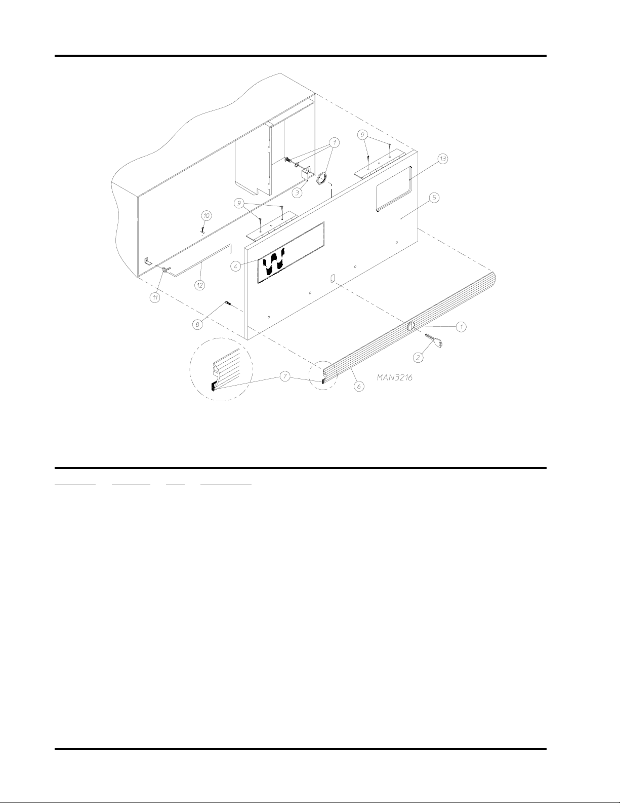
High Security Control Door Assembly
Illus. No. Part No. Qty. Description
1 160038 1 XX4451 Lock Assembly with Hardware
2 160140 1 XX4451 Key ONLY
3 160031 1 Lock Cam
4 112347 1 Wascodry Logo
5 881434* 1 High Security Control Door Assembly Less Lock
(includes illus. nos. 5 through 8)
881435* 1 High Security Textured Control Door Assembly LessLock
(includes illus. nos. 5 through 8)
6 180303 1 Top Black Trim Strip with Lock Hole
7 117603 3 Suppressor Tape/Gasket (sold in feet)
8 150201 4 #10-32 x 1/4” Phillips Round Head Machine Screw
9 150300 4 #10 x 1/2” Hex Washer TEK Screw
10 102600 1 Control Door Support Rod Catch
1 1 102601 1 Control Door Rod Retainer Clip
12 102505 1 Control Door Support Rod
13 117602 2 Suppressor Tape/Gasket (sold in feet)
* Specify color when ordering.
2 American Dryer Corp. 450195-3
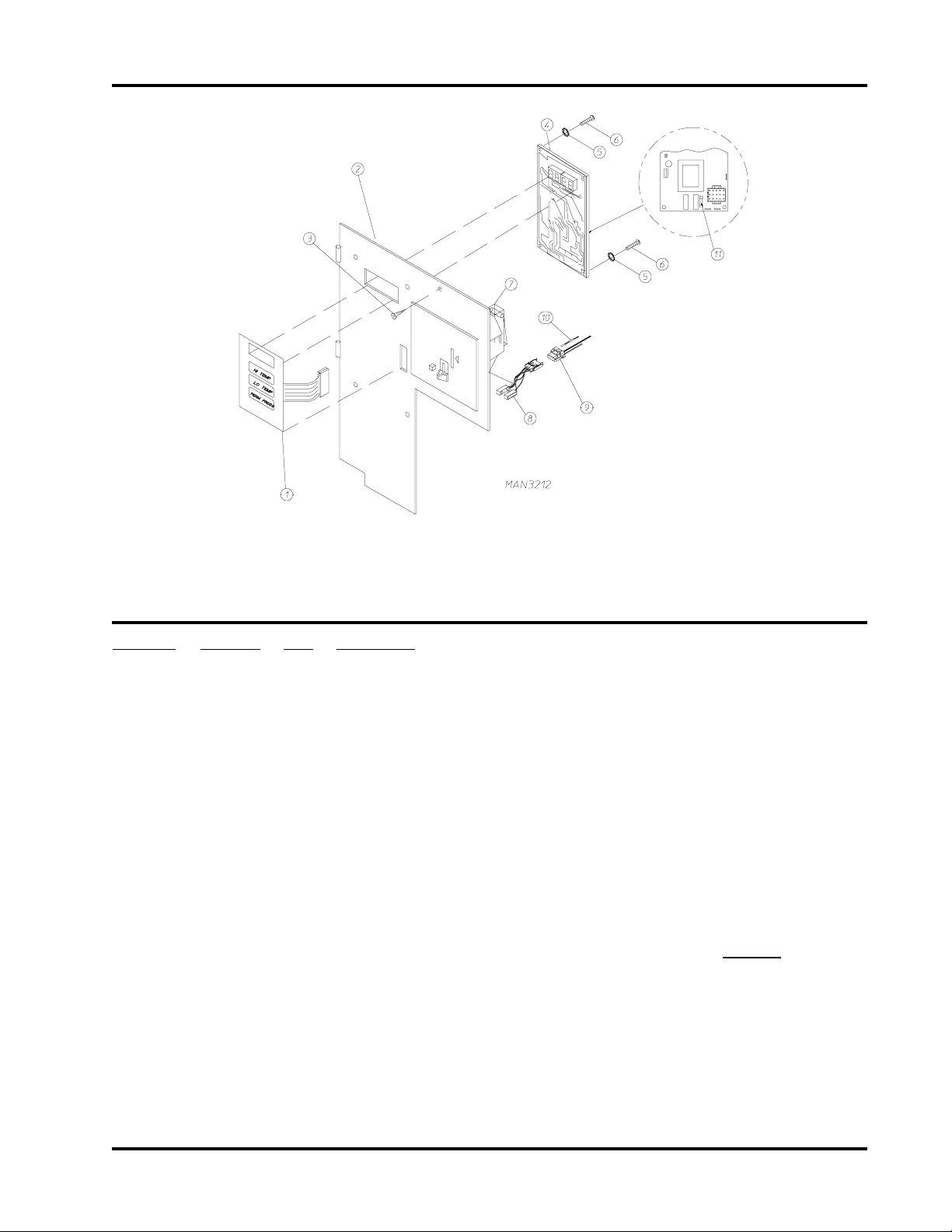
Phase 5 Coin Micropr ocessor Contr ol Panel Assembly
Illus. No. Part No. Qty. Description
1 112526 1 Coin Keyboard Label Assembly
2 881506 1 Coin Control Panel Assembly Less Acceptor
(includes illus. nos. 1, 2, 4, 5, 6 and 11)
881507 1 Coin Control Panel Assembly with Battery Bracket
Less Acceptor (includes illus. nos. 1, 2, 4, 5, 6 and 11)
881540 1 Coin Control Panel ONLY
881430 1 Coin Control Panel with Battery Bracket ONLY
3 150309 1 #10-16 x 1/2” HH TEK Crimptite Screw
4 137213 1 Phase 5 Coin Controller ONLY
824998 1 Phase 5 Battery Clip
5 153010 2 #6 S tar Washer
6 150005 2 #6-32 x 1/4” Phillips Round Head Machine Screw
7 --------- 1 Microprocessor Coin Acceptor with Optical Switch
(refer to Microprocessor Coin Acceptor Listing on page 28)
8 137056 1* Optic Switch ONLY
9 37023 1* Optic Switch Connector ONLY
10 137021 3* Microprocessor Socket ONLY
880772 1 Single Coin Optical Switch Harness
824080 1 Dual Coin Optical Switch Harness
122800 1 Microprocessor (female) Pin Extraction Tool
11 136048 1 1/8-Amp (Slo Blo) Fuse ONLY
* For Dual Coin Models, double the quantity.
450195-3 www.amdry.com 3
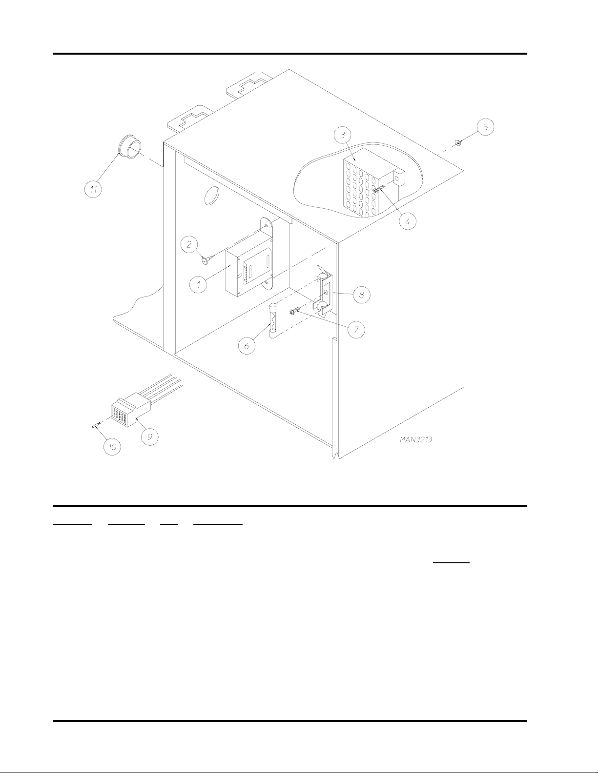
Phase 5 Micropr ocessor Contr ol Box Assembly
Illus. No. Part No. Qty. Description
1 --------- 1 Step Down Transformer
(refer to Step Down Transformer Usage Listing on page 29)
2 150300 2 #10 x 1/2” Hex Washer TEK Screw
3 120715 1 30-Position T erminal Block
4 150002 2 #6-32 x 1” Slotted Round Head Machine Screw
5 151000 2 #6-32 Pal Nut
6 136057 * 1/2-Amp (Slo Blo) Fuse
7 150301 * #8 x 7/16” Phillips Pan Head TEK Screw
8 136008 * Fuse Block/Strip ONLY
9 122641 1 15-Pin Microprocessor Connector
10 122706 * Socket T erminal ONLY
1 1 121400 1 7/8” Universal Bushing
* As required.
4 American Dryer Corp. 450195-3
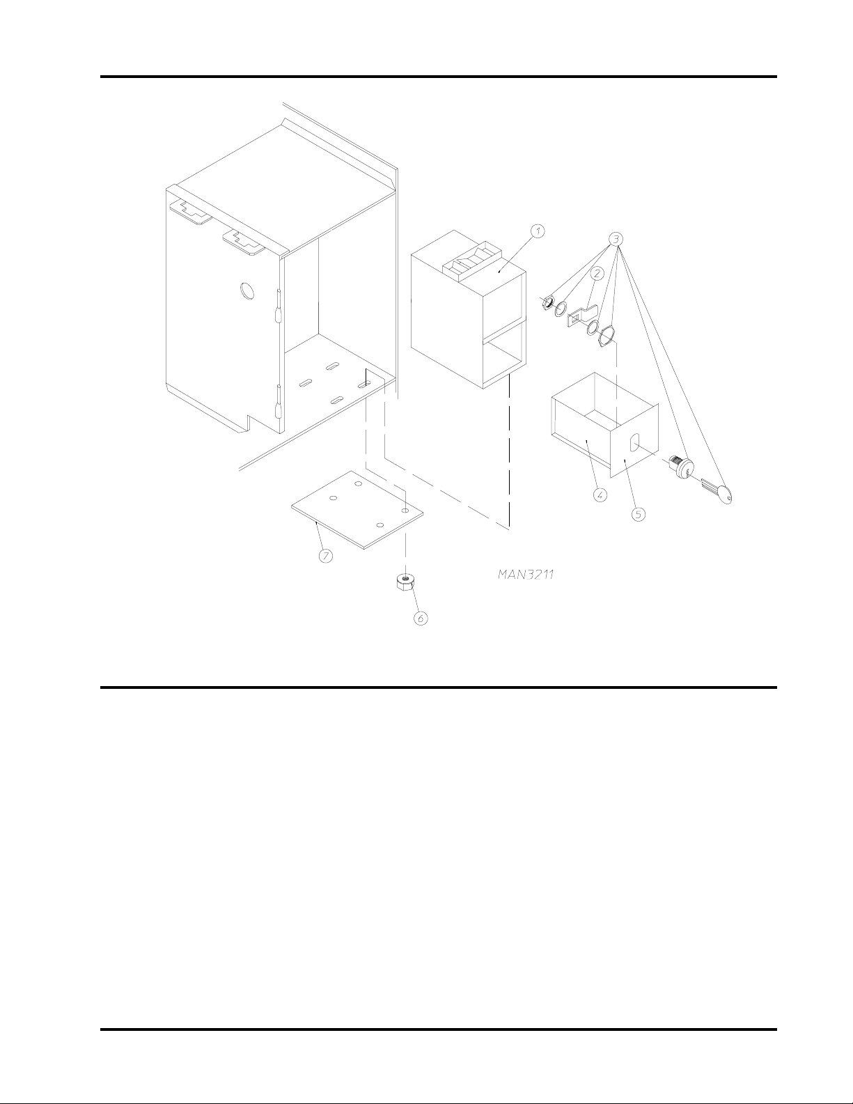
Coin Vault Assembly
Illus. No. Part No. Qty. Description
1 881431 1 Microprocessor Coin Vault Assembly Complete
(includes illus. nos. 1 through 6)
802123 1 Microprocessor Coin Vault ONLY
2 160006 Cam for 1/4-Turn Lock ONLY
3 875061 1 1/4-Turn Lock Assembly
(includes illus. nos. 2 and 3)
160007 1 1/4-Turn Lock with Key ONLY
160105* 1 1/4-Turn Mer-Pel Key ONLY
4 802020 1 1/4-Turn Coin Box Assembly
(includes illus. nos. 2 through 4)
802019 1 1/4 Turn Coin Box ONLY W ithout Faceplate
5 802018 1 1/4 T urn Coin Box Faceplate ONLY
6 152014 4 1/4-20 Free Spin Wash Nut
7 309250 1 Coin V ault Slot Cover
* Specify key number when ordering.
450195-3 www.amdry.com 5
Main Door “Steel” Assembly
6 American Dryer Corp. 450195-3

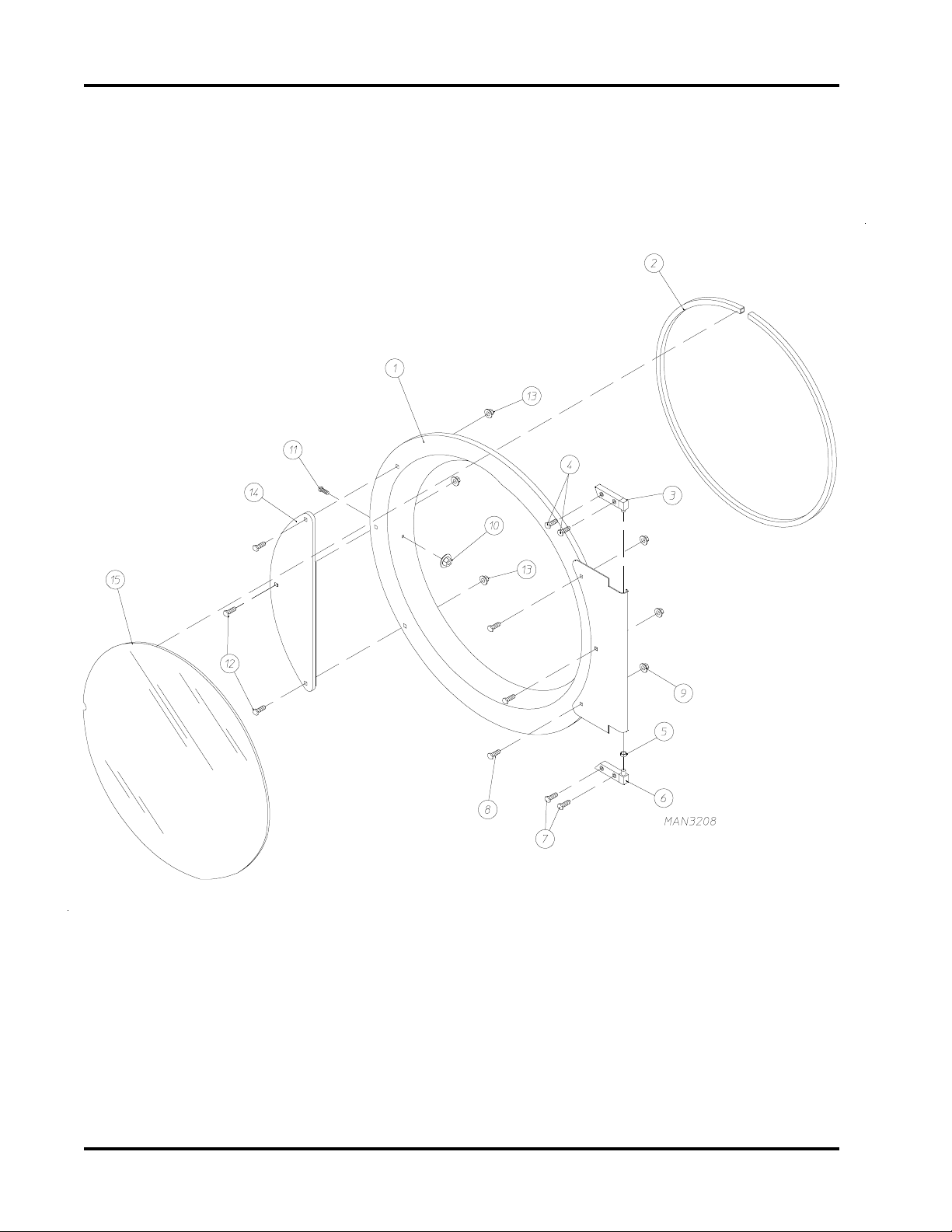
Main Door “Steel” Assembly
Illus. No Part No. Qty. Description
1 8 8 1150 1 Black Main Door Assembly Complete
(includes illus. nos. 1, 2, 8-15)
881207 1 Stainless Steel Main Door Assembly Complete
(includes illus. nos. 1, 2, 8-15)
2 102349 1 Door Gasket
170731 1 Gasket Adhesive (Black) 10.7 oz. Cartridge
170730 1 Gasket Adhesive (Clear) 10.7 oz. Cartridge
3 8 8 1152 1 Top Hinge Block (Black)
(includes illus. nos. 3 and 4)
881208 1 Top Hinge Block (Stainless Steel)
(includes illus. nos. 3 and 4)
4 150445 2 1/4-20 x 3/4” Black Cap Head Set Screw
150443 2 1/4-20 x 3/4” Stainless Steel Cap Head Set Screw
53031 1 1/4” Nylon Washer
6 8 8 1 1 5 1 1 Bottom Hinge Block (Black)
(includes illus. nos. 5, 6 and 7)
881209 1 Bottom Hinge Block (Stainless Steel)
(includes illus. nos. 5, 6 and 7)
7 150445 2 1/4-20 x 3/4” Black Cap Head Set Screw
150443 2 1/4-20 x 3/4” Stainless Steel Cap Head Set Screw
8 150683 3 Black 1/4-20 x 5/8 Carriage Bolt
150682 3 Polished 1/4-20 x 5/8 Carriage Bolt
(for models with stainless steel doors)
9 152014 3 1/2-20 Free Spin Wash Nut
10 151010 1 10-32 Hex Acorn Nut (Black)
151009 1 10-32 Hex Acorn Nut (Stainless Steel)
11 150120 1 Door Latch Screw
12 150683 3 Black 1/4-20 x 5/8 Carriage Bolt
150682 3 Polished 1/4-20 x 5/8 Carriage Bolt
(for models with stainless steel doors)
13 152014 3 1/2-20 Free Spin Wash Nut
14 881210 1 Black Main Door Handle ONLY
170333 1 Stainless Steel Main Door Handle ONLY
15 102211 1 20-9/16” Door Glass with Notch
170731 1 Glass Adhesive (Black) 10.3 oz. Cartridge
170730 1 Glass Adhesive (Clear) 10.3 oz. Cartridge
450195-3 www.amdry.com 7
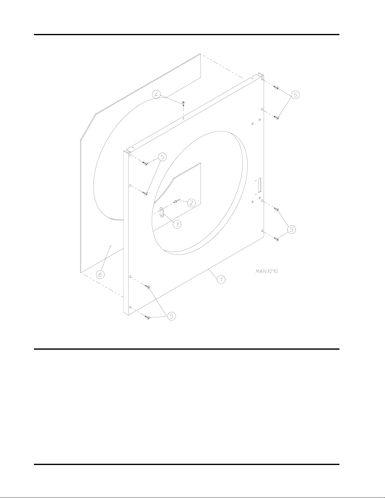
Insulated Front Panel Assembly
Illus. No. Part No. Qty. Description
1 881510 1* Insulated Front Panel Assembly
(includes illus. nos. 1, 2, 3 and 6)
881509 1* Textured and Insulated Front Panel Assembly
(includes illus. nos. 1, 2, 3 and 6)
2 154215 2 5/32” Pop Rivet
3 170330 1 Friction Door Latch
4 150300 1 #10 x 1/2” Hex Washer TEK Screw
5 150415 8 #10-16 x 1/2” Phillips Round Head Screw
6 116526 1 Front Panel Insulation
* Specify color when ordering.
8 American Dryer Corp. 450195-3

Main Door Switch Assembly
Illus. No. Part No. Qty. Description
1 153565 2 #6-32 x 1” Clinch Stud
2 152013 2 #6-32 Hex Nut
3 153010 2 #6 S tar Washer
4 137005 1 Door Switch
5 122636 2 Flag T erminal
6 881211 1 Black Main Door Switch Housing ONLY
88 1153 1 Black Main Door Switch Housing Complete
(includes illus. nos. 1, 2, 3, 4 and 6)
7 150301 2 #8 x 7/16” Phillips Head TEK Screw
450195-3 www.amdry.com 9

Dr op Lint Door Assembly
Illus. No. Part No. Qty. Description
1 160039 1 Lint Door Lock
2 160140 1 Key ONLY for XX 4451 Lock
3 881436* Insulated Drop Lint Door Assembly Complete
(includes illus. nos. 3 through 7)
881437* Insulated T extured Drop Lint Door Assembly Complete
(includes illus. nos. 3 through 7)
4 150201 10 #10-32 x 1/4” Phillips Pan Head TEK Screw
5 117600 Noise Suppressor Tape (sold in feet)
6 117603 5 Suppressor Tape / Gasket (sold in feet)
7 180313 2 Black Trim
8 150419 2 #6 x 1/2” Tamperproof TEK Screw
--- 150418 1 T amperproof Screw Hand Driver
9 108120 1 Chain for Drop Lint Door (10-1/2” length)
* Specify color when ordering.
10 American Dryer Corp. 450195-3

Lint T rap Assembly
Illus. No. Part No. Qty. Description
1 881432 1 Lint Trap ONLY
881433 1 Lint Trap Assembly Complete
(includes illus. nos. 1 thru 5)
2 154200 7 5/32” Pop Rivet
3 150300 3 #10 x 1/2” Hex Washer TEK Screw
4 304100 1 Lint Trap Screen Hold Down
5 800500 2 Lint Screen
6 50419 2 #6 x 1/2” Tamperproof Screw
- 150418 1 Tamperproof Screw Hand Driver
7 108120 1 Chain for Drop Lint Door (10-1/2” length)
450195-3 www.amdry.com 11

Basket (T umbler) / Support Assemblies
12 American Dryer Corp. 450195-3

Basket (T umbler) / Support Assemblies
Illus. No. Part No. Qty. Description
1 800830 1 AD-385 Basket and Support Assembly Complete with Felt
Collars (includes illus. nos. 1 through 11)
800890 Complete with Felt Collar
(includes illus. nos. 1 through 11)
800720* 1 AD-385 Basket Only without Felt Collars
(includes illus. nos. 1, 2, and 6)
800840* 1 AD-385 Stainless Steel Basket ONLY without Felt Collar
(includes illus. nos. 1, 2, and 6)
2 301315 2 AD-385 (short) Basket Rib ONLY
301316 1 AD-385 (tall) Basket Rib ONLY
301414 2 AD-385 Stainless Steel (short) Basket Rib ONLY
301415 1 AD-385 Stainless Steel (tall) Basket Rib ONLY
3 150518 1 5/16-18 x 3/8” Socket Button Head Screw
4 882050 3 5/16-18 x 31” Tie Rod
5 153001 3 5/16” Flat Washer
6 150313 30 #10-16 x 1/2” TORX+ BTN Type 1
7 800612 1 AD-385 Basket (Tumbler) Support ONLY
8 152004 3 5/16-18 Hex Nut
9 153002 3 5/16” Lock Washer
10 153001 3 5/16” Flat Washer
1 1 116003 1 Felt Collar ONLY
--- 401010 1 #847 Adhesive for Felt Collar (5 oz Tube)
* Felt collar not included and must be ordered separately.
450195-3 www.amdry.com 13

T umbler Bearing Assembly
14 American Dryer Corp. 450195-3

T umbler Bearing Assembly
Illus. No. Part No. Qty. Description
1 880203 1 1-3/8” Flange Bearing
2 153005 4 3/8” Lock Washer
3 152005 4 3/8-16 Hex Nut
4 150508 2 3/8-16 x 3/4” Hex Head Machine Bolt
5 153005 2 3/8” Lock Washer
6 152005 2 3/8-16 Hex Nut
7 150600 2 3/8-16 x 1/2” Hex Head Machine Bolt
8 153004 2* 3/8” Flat Washer
9 153005 2 3/8” Lock Washer
10 152005 2 3/8-16 Hex Nut
11 150501 4 5/16-18 x 3/4” Hex Head Machine Bolt
12 153002 4 5/16” Lock Washer
13 153001 4 5/16” Flat Washer
14 150621 2 5/16-18 x 1-1/2” Hex Head Machine Bolt
15 152004 2 5/16-18 Hex Nut
16 80 110 1 1 1-3/8” Bearing Box Assembly Complete
(for models mfg. without Rotational Sensor)
(includes illus. nos. 4 through 20)
801 103 1 1-3/8” Bearing Box and Support Assembly ONLY
(includes illus. nos. 4, 5, 6, 16, and 17)
801105 1 1-3/8” Bearing Box ONLY
17 80 1104 1 1-3/8” Pillow Block Bearing Support ONLY
18 880202 1 1-3/8” Pillow Block Bearing ONLY
19 152004 2 5/16-18 x 1-1/2” Allen Set Screw
22 154301 2 5/16-18 x 5/16” Allen Set Screw
23 100713 1 1/4” x 1/4” x 7/8” Key
24 100189 1 5L650 “V” Belt (to idler assembly)
* Some models require a quantity of 4.
450195-3 www.amdry.com 15

Idler Bearing Assembly
16 American Dryer Corp. 450195-3

Idler Bearing Assembly
Illus. No. Part No. Qty. Description
1 100111 1 5L650 “V” Belt (basket / tumbler to idler)
(prior to April 16, 1999)
100189 1 5L540 “V” Belt (basket / tumbler to idler)
(as of April 16, 1999)
2 1 0 1129 1 9” x 2-1/2” Compound Pulley ONLY
3 100101 1 4L480 “V” Belt (idler to motor)
4 54301 4 5/16-18 x 1 Cone Point Set Scew
5 100705 1 3/16” x 3/16” x 1-3/8” Key
6 301850 1 5/8” x 3/4” Idler Shaft ONLY
7 150529 3 1/4-20 x 2-1/4” Carriage Bolt
8 100214 2 5/8” Flange Bearing (with flanges) ONLY
9 153007 3 1/4” Lock Washer
10 152002 3 1/4-20 Hex Nut
11 801008 1 Idler Bearing Assembly Complete
(includes illus. nos. 6 through 22)
100406 1 Idler Bearing Mount ONLY
2 150613 1 5/16-18 x 4” Hex Head Machine Bolt
13 150617 2 3/8-16 x 1” Hex Head Machine Bolt
14 153005 2 3/8” Lock Washer
15 153004 2 3/8” Flat Washer
16 152020 1 5/16-18 Standard Square Nut
17 152004 1 5/16-18 Hex Nut
18 152005 1 3/8-16 Hex Nut
19 153005 1 3/8” Lock Washer
20 150617 1 3/8-16 x 1” Hex Head Machine Bolt
21 301851 1 Idler Bracket Adjustment Plate
22 801009 1 Idler Square Washer
450195-3 www.amdry.com 17

Totally Enclosed, Fan-Cooled (T .E.F.C.) Motor Mount Assembly
18 American Dryer Corp. 450195-3

Totally Enclosed, Fan-Cooled (T .E.F.C.) Motor Mount Assembly
Illus. No. Part No. Qty. Description
1 100101 1 4L480 “V” Belt (to idler assembly)
2 101133 1 5/8” x 2-1/4” Sheave
(for use on 1Ø - 60 Hz Motors ONLY)
3 150501 4 5/16-18 x 3/4” Hex Head Machine Bolt
4 153002 4 5/16” Lock Washer
5 153001 4 5/16” Flat Washer
6 100073 1 1 H P 115/230v 60 Hz 1Ø T.E.F.C. Plug-Type Motor
7 122701 8 Socket Terminal ONLY
122801 1 Pin/Socket Extraction T ool
8 137030 1 8-Pin Housing Connector
9 152004 4 5/16-18 Hex Nut
10 153002 4 5/16” Lock Washer
11 153001 4 5/16” Flat Washer
12 117600 4 Noise Suppressor Tape (sold in feet)
13 154000 4 5/16-18 Tinnerman Nut
14 800911 1 1 HP Motor Mount ONLY
881661 1 1 HP 120-230V 1ø 60 Hz Motor Mount Assembly Complete
(includes illus. nos. 2 through 12 and 19)
15 153050 2 1/2” S.A.E. Flat Washer
16 100603 1 16” Impellor (fan/blower) with 3/4” Bore
17 100702 1 1/8” x 1/8” x 1-1/2” Key
18 153050 2 1/2” S.A.E. Flat Washer
19 152006 2 1/2-20 Left Hand Jam Nut
450195-3 www.amdry.com 19

Sensor Bracket Assemblies
20 American Dryer Corp. 450195-3

Sensor Bracket Assemblies (continued)
Illus. No. Part No. Qty. Description
1 880251 1 1/4” Temperature Sensor Probe Assembly
(includes illus. nos. 1 and 5 through 8)
2 130103 1 225° Large Automatic Thermostat
3 153010 2 #6 Star Washer
4 152000 2 #6-32 Hex Nut
5 21028 2 Insulated T erminal ONL Y
6 122701 4 Socket T erminal ONLY
7 122605 1 4-Pin Socket ONLY
8 154007 2 1/4” Tinnerman Push-on Fastener
9 150005 2 #6-32 x 1/4” Round Head Machine Screw
10 801425 1 Microprocessor Sensor Bracket Assembly Complete
(includes illus. nos. 1 through 10)
305007 1 Universal Sensor Bracket ONLY
11 122604 1 4-Pin Connector ONLY
12 122700 4 Pin Terminal ONLY
13 150301 2 #8-18 X 7/16” Phillips Pan Head TEK Screw
450195-3 www.amdry.com 21

Direct Spark Ignition (DSI) Burner Assembly
22 American Dryer Corp. 450195-3

Direct Spark Ignition (DSI) Burner Assembly
Illus. No. Part No. Qty. Description
1 318030 1 DSI Burner Shield ONLY
2 150300 2 #10 x 1/2” Hex Washer TEK Screw
3 150415 2 #10-16 x 1/2” Phillips Round Head Crimptite Screw
4 880134 1 DSI Ignitor/Flame-Probe Assembly Kit
(includes high voltage [HV] wire and connector)
305410 1 DSI Ignitor Gap Feeler Gauge ... Not Illustrated
5 880330 1 DSI Ignitor HV Wire/Connector ONLY
6 150103 2 8-32 x 3/4” Pan Head Machine Screw
7 153000 2 #8 Steel Burr
8 151001 2 8-32 Pal Nut
9 141105 2 Large Gas “T” Burner
10** 140822 2 #27 Burner Orifice (natural gas) ONLY
140808 2 #44 Burner Orifice (liquid propane) ONLY
11 141230 1 1/2” 2-Port DSI Manifold
12 318700 1 Pipe Bracket (bent)
13 150300 2 #10 x 1/2” Hex Washer TEK Screw
14 128927 1 1/2” 24 VAC Redundant (natural gas) Gas Valve
140411 1 1/2” 24 VAC Gas Valve L.P . (liquid propane) Conversion Kit
880960 1 1/2” DSI L.P. (Liquid Propane) Gas Valve Assembly
15 141313 1 90°1/2 X 1” Gas Shutoff Assembly
16 142809 1 1/2” x 29-1/8” Pipe
17 150309 2 10-16 x 1/2” Phillips HH TEK Crimptite Screw
18 318712 1 Pipe Bracket
19 850858 1 Burner Box ONLY
881607* 1 385 DSI (Natural) Burner Assembly Complete Less Orifice
(includes illus. nos. 1 through 9 and 11 through 19)
881608* 1 385 DSI (L.P.) Burner Assembly Complete Less Orifice
(includes illus. nos. 1 through 9 and 11 through 19)
20 880815 1 DSI Module Only (50/60 Hz)
21 150299 4 #10 x 1” Hex Washer TEK Screw
xx 881478** 1 Dryer L.P. Conversion Kit
* Burner orifices are not included and must be ordered separately.
** Consult factory for elevations over 2,000 feet.
450195-3 www.amdry.com 23

ADG-385 Sail Switch / Hi-Limit Assembly
24 American Dryer Corp. 450195-3

ADG-385 Sail Switch / Hi-Limit Assembly
Illus. No. Part No. Qty. Description
1 154004 1 Twin Speed Nut
2 150415 2 10-16 x 1/2” Phillips Round Head Crimptite Screw
3 802799 1 Sail Switch Box Cover and Bracket ONLY
4 150303 2 #4 x 3/4” Pan Head “A” Machine Screw
5 122200 1 Sail Switch ONLY
6 105500 1 Sail Switch Actuator Rod
7 319202 1 Sail Switch Damper (flat)
8 54002 1 1/8” Push-On Fastener
9 802800 1 Sail Switch Box With Cover and Bracket ONLY
802801 1 Sail Switch Box Assembly Complete
(includes illus. nos. 1 through 8)
10 142809 1 1/2” x 29-1/8” Pipe
11 150415 2 #10-16 x 1/2” Phillips Round Head Crimptite Screw
12 319704 1 Hi-Limit Mounting Bracket ONLY
13 151000 2 #6-32 Pal Nut
14 150001 2 #6-32 x 1/2” Round Head Machine Screw
15 130401 1 330°Hi-Limit
450195-3 www.amdry.com 25

Single Phase Motor, Electric Relay Panel Assembly
Illus. No. Part No. Qty. Description
1 132451 1 2-Pole Contactor - 24 VAC
2 150299 2 #10 x 1” Hex Head Screw
3 824828 1 RC Network with Connectors
(for Microprocessor Models ONLY)
322809 1 Back Electrical Box Cover ... Not Illustrated
150301 5 #8-18 x 7/16” Phillips Pan Head TEK Screw ... Not Illustrated
26 American Dryer Corp. 450195-3

Outer Top / Back Guard Assembly
Illus. No. Part No. Qty. Description
1 330605 1 Outer Top
2 330606 1 Top Back Guard Assembly
3 322809 1 Back Electrical Box Cover
4 330604 1 Lower Back Guard Assembly
5 150301 10 #8-18 x 7/16” Phillips Pan Head TEK Screw
6 103500 4 Leveling Leg
7 150300 9 #10 x 1/2” Hex Washer TEK Screw
8 150301 5 #8-18 x 7/16” Phillips Pan Head TEK Screw
9 150301 7 #8-18 x 7/16” Phillips Pan Head TEK Screw
450195-3 www.amdry.com 27

Micropr ocessor Coin Acceptor Listing
NOTE: Coin acceptors listed include optical switch (ADC Part No. 137056).
Single Coin*
Part Numer Nation Description
125100 United States and Canada 25¢ Optic Coin Acceptor
125114 United Kingdom 20 New Pence Optic Coin Acceptor
125102 Belgium 5 Belgian Franc Optic Coin Acceptor
125120 France 2 French Franc Optic Coin Acceptor
125124 France 5 French Franc Optic Coin Acceptor
125137 Denmark New 1 Danish Krone Optic Coin Acceptor
125140 Denmark New 2 Danish Krone Optic Coin Acceptor
125107 Austrailia 20¢ Austrailian Optic Coin Acceptor
125130 Austrailia $1 Austrailian Optic Coin Acceptor
125123 New Zealand 50¢ New Zealand Optic Coin Acceptor
125132 Singapore 50¢ Singapore Optic Coin Acceptor
125104 Japan 100 Yen Optic Coin Acceptor
125133 Hong Kong $1 Hong Kong Optic Coin Acceptor
125103 --- .882 Token Optic Coin Acceptor
125121 --- .800 Token Optic Coin Acceptor
125129 --- Muller Token Optic Coin Acceptor
Dual Coin*
Part Numer Nation Description
125128 Canada 25¢/$1 Dual Optic Coin Acceptor
125113 United Kingdom 1£
125119 Belgium 5/20 Belgian Franc Dual Optic Coin Acceptor
125122 France 2/5 French Franc Dual Optic Coin Acceptor
125134 Denmark New 1/5 Danish Krone Dual Optic Coin Acceptor
125139 Denmark New 2/5 Danish Krone Dual Optic Coin Accepto
125126 Netherlands 25/1 Dutch Guilder Dual Optic Coin Acceptor
* Consult Factory For Coin Acceptors Not Listed.
/20 Pence Dual Optic Coin Acceptor
28 American Dryer Corp. 450195-3

ADG-385 Step Down Transformer Usage Listing
Voltage W ir e S er vic e
208/2 40 3 or 4 ---- -----
380 3 132059
380 4 132059
416 3 132062
416 4 132062
Step Down Transforme r
Part N o.
460/480 3 132053
ADG-385
NOTE: Step Down Transformer used on models mfd. for 380 volts or higher.
460/480 4 132053
575 3 132050
450195-3 www.amdry.com 29

Part No. Description
112027 “W ater W ashed Fabrics” Label
112040 “Lint Compartment” Label
112041 “Caution-Exhausted” Label
112533 Phase 5 Coin “Program Location Summary” Label
112534 Phase 5 OPL Program Location Summary” Label
120100 3/8” Straight (BX) Connector
120300 3/8” x 45°(BX) Connector
120400 3/8” Red Jacket (BX) Insulator
120500 3/8” Jiffy Clip (BX Retainer Clip)
120600 3/8” Greenfield (BX)
120707 Terminal Strip (2-position)
120708 Terminal Strip (3-position)
120800 1/4” In-Line Connector
120802 Red Butt Connector
120902 #74B Wire Nut
120903 Crimp-on Wire Nut
121014 1/4” Insulated (female) T erminal
121026 T ab Receptacle Combination
121499 4” Harness Tie
121500 7” Harness Tie
121503 Harness Tie Mounting Clip
122804 Manometer (water column test gauge)
404500 Almond Brush-In-Cap Bottle T ouch-Up Paint
404502 White-Brush-In-Cap Bottle Touch-Up
404506 Beige Brush-In-Cap Bottle Touch-Up Paint
404507 Cornflower Blue Brush-In-Cap Bottle Touch-Up Paint
880200 Electrical T erminal (assortment) Kit
Additional Parts Available
30 American Dryer Corp. 450195-3

ADC 450195 3 - 03/23/05-0
 Loading...