

American Dryer ML-758 User Manual
ML-758 Installation Manual
Phase 7 / DSI / Dual Timer / F.S.S.
WARNING: For your safety the information
in this manual must be followed to
minimize the risk of fire or explosion and
to prevent property damage, personal
injury or death.
— Do not store or use gasoline or other
flammable vapors and liquids in the
vicinity of this or any other appliance.
— WHAT TO DO IF YOU SMELL GAS:
●
Do not try to light any appliance.
●
Do not touch any electrical switch;
do not use any phone in your
building.
●
Clear the room, building or area of
all occupants.
●
Immediately call your gas supplier
from a neighbor’s phone. Follow
the gas supplier’s instructions.
●
If you cannot reach your gas
supplier, call the fire department.
— Installation and service must be
performed by a qualified installer,
service agency or the gas supplier.
AVERTISSEMENT: Assurez-vous de
bien suivre les instructions données dans
cette notice pour réduire au minimum le
risque d’incendie ou d’explosion ou pour
éviter tout dommage matériel, toute
blessure ou la mort.
—Ne pas entreposer ni utiliser d’essence
ni d’autres vapeurs ou liquides
inflammables à proximité de cet
appareil ou de tout autre appareil.
—QUE FAIRE SI VOUS SENTEZ UNE
ODEUR DE GAZ:
●
Ne pas tenter d’allumer d’appareils.
●
Ne touchez à aucun interrupteur. Ne
pas vous servir des téléphones se
trouvant dans le bâtiment.
●
Évacuez la pièce, le bâtiment ou la
zone.
●
Appelez immédiatement votre
fournisseur de gaz depuis un voisin.
Suivez les instructions du fournisseur.
●
Si vous ne pouvez rejoindre le
fournisseur de gaz, appelez le service
des incendies.
—L’installation et l’entretien doivent être
assurés par un installateur ou un
service d’entretien qualifié ou par le
fournisseur de gaz.
American Dryer Corporation
88 Currant Road
Fall River MA 02720-4781 USA
Telephone: +1 (508) 678-9000 / Fax: +1 (508) 678-9447
e-mail: techsupport@amdry.com
www.amdry.com
ADC Part No. 113226-6
Retain This Manual in a Safe Place for Future Reference
This product embodies advanced concepts in engineering, design, and safety. If this product is properly
maintained, it will provide many years of safe, efficient, and trouble free operation.
Only qualified technicians should service this equipment.
OBSERVE ALL SAFETY PRECAUTIONS displayed on the equipment or specified in the installation
manual included with the dryer.
The following “FOR YOUR SAFETY” caution must be posted near the dryer in a prominent location.
FOR YOUR SAFETY
Do not store or use gasoline
or other flammable vapors
and liquids in the vicinity of
this or any other appliance.
We have tried to make this manual as complete as possible and hope you will find it useful. The manufacturer
reserves the right to make changes from time to time, without notice or obligation, in prices, specifications,
colors, and material, and to change or discontinue models. The illustrations included in this manual may not
depict your particular dryer exactly.
POUR VOTRE SÉCURITÉ
Ne pas entreposer ni utiliser d’essence
ni d’autres vapeurs ou liquides
inflammables à proximité de cet
appareil ou de tout autre appareil.
IMPORTANT
For your convenience, log the following information:
DATE OF PURCHASE __________________________________________________ MODEL NO. ________________________
RESELLER’S NAME ______________________________________________________________________________________
ML-758 Phase 7
SERIAL NUMBER(S) ______________________________________________________________________________________
_______________________________________________________________________________________________________
_______________________________________________________________________________________________________
Replacement parts can be obtained from your reseller or the ADC factory. When ordering replacement parts
from the factory, you can FAX your order to ADC at +1 (508) 678-9447 or telephone your order directly to the
ADC Parts Department at +1 (508) 678-9000. Please specify the dryer model number and serial number in
addition to the description and part number, so that your order is processed accurately and promptly.
“IMPORTANT NOTE TO PURCHASER”
Information must be obtained from your local gas supplier on the
instructions to be followed if the user smells gas. These instructions
must be posted in a prominent location near the dryer.
!
▲ WARNING
Proposition 65
Use of this product could expose you to substances from fuel combustion
that contain chemicals known to the State of California to cause cancer,
birth defects and other reproductive harm.
IMPORTANT
YOU MUST DISCONNECT AND LOCKOUT THE ELECTRIC SUPPLY AND THE GAS
SUPPLY OR THE STEAM SUPPLY BEFORE ANY COVERS OR GUARDS ARE
REMOVED FROM THE MACHINE TO ALLOW ACCESS FOR CLEANING,
ADJUSTING, INSTALLATION, OR TESTING OF ANY EQUIPMENT PER OSHA
(Occupational Safety and Health Administration) STANDARDS.
“Caution: Label all wires prior
to disconnection when
servicing controls. Wiring
errors can cause improper
operation.”
«Attention: Au moment de l’entretien des
commandes, étiquetez tous les fils avant de les
débrancher. Des erreurs de câblage peuvent
entraîner un fonctionnement inadéquat et
dangereux.»
CAUTION
DRYERS SHOULD NEVER BE LEFT UNATTENDED WHILE IN OPERATION.
WARNING
CHILDREN SHOULD NOT BE ALLOWED TO PLAY ON OR NEAR THE DRYER(S).
CHILDREN
SHOULD BE SUPERVISED IF NEAR DRYERS IN OPERATION.
FOR YOUR SAFETY
DO NOT DRY MOP HEADS IN THE DRYER.
DO NOT USE DRYER IN THE PRESENCE OF DRY CLEANING FUMES.
WARNING
UNDER NO CIRCUMSTANCES should the dryer door switches, lint drawer switch,
or heat safety circuit ever be disabled.
WARNING
The dryer must never be operated with any of the back guards, outer tops, or
service panels removed. PERSONAL INJURY OR FIRE COULD RESULT.
WARNING
DRYER MUST NEVER BE OPERATED WITHOUT THE LINT FILTER/SCREEN IN
PLACE, EVEN IF AN EXTERNAL LINT COLLECTION SYSTEM IS USED.
IMPORTANT
PLEASE OBSERVE ALL SAFETY PRECAUTIONS displayed on the equipment
and/or specified in the installation manual included with the dryer.
Dryer must not be installed or stored in an area where it
weather.
The wiring diagram for the dryer is located in the front electrical control box area.
will be exposed to water or
IMPORTANT
Dryer must be installed in a location/environment, which the ambient temperature
remains between 40° F (4.44° C) and 130° F (54.44° C).

Table of Contents
SECTION I
SAFETY PRECAUTIONS .................................................................................................................................. 2
SECTION II
SPECIFICATIONS/COMPONENT IDENTIFICATION ......................................................................................... 4
A. Specifications........................................................................................................................................4
B. Component Identification ....................................................................................................................... 6
SECTION III
INSTALLATION PROCEDURES ........................................................................................................................ 8
A. Location Requirements ......................................................................................................................... 8
B. Unpacking/Setting Up ........................................................................................................................... 9
C. Dryer Enclosure Requirements ............................................................................................................. 9
D. Fresh Air Supply Requirements ........................................................................................................... 10
E. Exhaust Requirements ........................................................................................................................ 11
F. Electrical Information........................................................................................................................... 15
G. Gas Information ................................................................................................................................... 19
H. Steam Information ............................................................................................................................... 22
I. Preparation for Operation/Start-Up....................................................................................................... 26
J. Preoperational Test ............................................................................................................................. 27
K. Preoperational Instructions ................................................................................................................. 29
L. Shutdown Instructions......................................................................................................................... 31
SECTION IV
SERVICE/PARTS INFORMATION ................................................................................................................... 32
A. Service ................................................................................................................................................ 32
B. Parts ................................................................................................................................................... 32
SECTION V
WARRANTY INFORMATION ........................................................................................................................... 33
A. Returning Warranty Cards ................................................................................................................... 33
B. Warranty ............................................................................................................................................. 33
C. Returning Warranty Parts .................................................................................................................... 33
SECTION VI
ROUTINE MAINTENANCE ............................................................................................................................... 35
A. Cleaning .............................................................................................................................................. 35
B. Adjustments ....................................................................................................................................... 36
C. Lubrication .......................................................................................................................................... 36
D. Lint Drawer Removal ........................................................................................................................... 37
SECTION VII
DATA LABEL INFORMATION .......................................................................................................................... 38
SECTION VIII
PROCEDURE FOR FUNCTIONAL CHECK OF REPLACEMENT COMPONENTS ........................................... 39
SECTION IX
MANUAL RESET BURNER HI-LIMIT INSTRUCTIONS ................................................................................... 42
A. Phase 7 .............................................................................................................................................. 42
B. Dual Timer .......................................................................................................................................... 42
SECTION X
FIRE SUPPRESSION SYSTEM (F.S.S.) ......................................................................................................... 43
SECTION I
SAFETY PRECAUTIONS
WARNING: For your safety, the information in this manual must be followed to minimize the risk of
fire or explosion or to prevent property damage, personal injury, or loss of life.
WARNING: The dryer must never be operated with any of the back guards, outer tops, or
service panels removed. PERSONAL INJURY OR FIRE COULD RESULT.
1. DO NOT store or use gasoline or other flammable vapors and liquids in the vicinity of this or any other
appliance.
2. Purchaser/user should consult the local gas supplier for proper instructions to be followed in the event the
user smells gas. The instructions should be posted in a prominent location.
3. WHAT TO DO IF YOU SMELL GAS:
a. DO NOT try to light any appliance.
b. DO NOT touch any electrical switch.
c. DO NOT use any phone in your building.
d. Clear the room, building, or area of
e. Immediately call your gas supplier from a neighbor’s phone. Follow the gas supplier’s instructions.
f. If you
4. Installation and service must be performed by a qualified installer, service agency, or gas supplier.
5. Dryer(s) must be exhausted to the outdoors.
6. Although ADC produces a very versatile dryer, there are some articles that, due to fabric composition or
cleaning method, should not be dried in it.
cannot reach your gas supplier, call the fire department.
ALL occupants.
WARNING: Dry only water washed fabrics. DO NOT dry articles spotted or washed in dry
cleaning solvents, a combustible detergent, or “all purpose” cleaner. EXPLOSION
COULD RESULT.
WARNING: DO NOT dry rags or articles coated or contaminated with gasoline, kerosene, oil, paint,
or wax. EXPLOSION COULD RESULT.
WARNING: DO NOT dry mop heads. Contamination by wax or flammable solvents will create a
fire hazard.
WARNING: DO NOT use heat for drying articles that contain plastic, foam, sponge rubber, or
similarly textured rubber materials. Drying in a heated basket (tumbler) may damage
plastics or rubber and may be a fire hazard.
2 American Dryer Corp. 113226- 6
7. A program should be established for the inspection and cleaning of lint in the burner area, exhaust ductwork,
and area around the back of the dryer. The frequency of inspection and cleaning can best be determined
from experience at each location.
WARNING: The collection of lint in the burner area and exhaust ductwork can create a potential fire
hazard.
8. For personal safety, the dryer must be electrically grounded in accordance with local codes and/or the
National Electrical Code ANSI/NFPA NO. 70-LATEST EDITION or in Canada, the Canadian Electrical
Codes Parts 1 & 2 CSA C22.1-1990 or LATEST EDITION.
NOTE: Failure to electrically ground the dryer properly will VOID THE WARRANTY.
9. UNDER NO CIRCUMSTANCES should the dryer door switches, lint drawer switch, or heat safety
circuit ever be disabled.
WARNING: PERSONAL INJURY OR FIRE COULD RESULT SHOULD THE DRYER
DOOR SWITCHES, LINT DRAWER SWITCH, OR HEAT SAFETY CIRCUIT
EVER BE DISABLED.
10. This dryer is not to be used in the presence of dry cleaning solvents or fumes.
11. Remove articles from the dryer as soon as the drying cycle has been completed.
WARNING: Articles left in the dryer after the drying and cooling cycles have been completed can
create a fire hazard.
12. READ AND FOLLOW ALL CAUTION AND DIRECTION LABELS ATTACHED TO THE
DRYER.
13. For safety, proper operation, and optimum performance, the dryer must not be operated with a load less
than sixty-six percent (66%), 50 lb (22.7 kg) of its rated capacity.
WARNING: YOU MUST DISCONTINUE AND LOCK OUT THE ELECTRIC SUPPLY
AND THE GAS SUPPLY OR STEAM SUPPLY BEFORE ANY COVERS OR
GUARDS ARE REMOVED FROM THE DRYER TO ALLOW ACCESS FOR
CLEANING, ADJUSTING, INSTALLATION, OR TESTING OF ANY
EQUIPMENT PER OSHA (Occupational Safety and Health Administration)
STANDARDS.
IMPORTANT: Dryer must be installed in a location/environment, which the ambient
temperature remains between 40° F (4.44° C) and 130° F (54.44° C).
113226- 6 www.amdry.com 3
SPECIFICATIONS/COMPONENT IDENTIFICATION
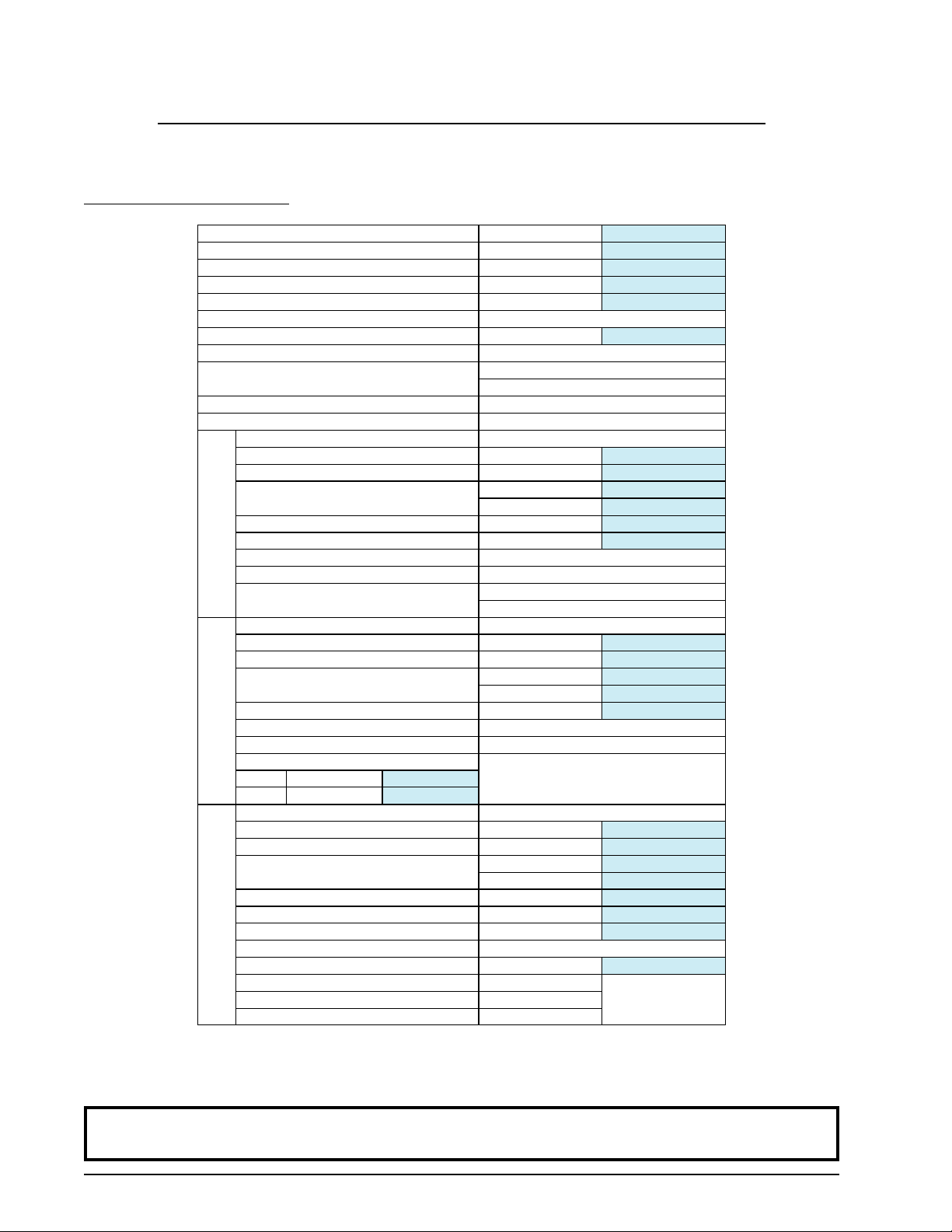
A. SPECIFICATIONS
SECTION II
MAXIMUM CAPACITY (DRY WEIGHT) 75 lb
TUMBLER DIAMETER 37”
TUMBLER DEPTH 36”
TUMBLER VOLUME 22.40 cu ft
TUMBLER/DRIVE MOTOR 1 hp *
BLOWER/FAN MOTOR N / A
DOOR OPENING (DIAMETER) 31-3/ 8”
DOOR SILL HEIGHT N / A
WATER CONNECTION 3/4”-11.5 NH
3/4” B.S.P.T. (Outside North America)
DRYERS PER 20’ /40’ C ONTAINER 10 / 20
DRYERS PER 48’ /53’ TRUCK 24 / 26
VOLTAGE AVAILABLE 120-575V 1,3ø 2,3,4w 50/60 Hz
APPROXIMATE NET WEIGHT 741 lb
APPROXIMATE SHIPPING WEIGHT 793 lb
kcal/h r
25,800
60 Hz
50 Hz
60 Hz
50 Hz
60 Hz
50 Hz
1,000 cfm
833 cfm
3/4” B.S.P.T.
1,000 cfm
833 cfm
1,000 cfm
833 cfm
(CE and Australia Only)
AIRFLOW
HEAT INPUT 175,000 Btu/hr
EXHAUST CONNECTION (DIAMETER) 8”
GAS
COMPRESSED AIR CONNECTION N / A
COMPRESSED AIR VOLUME N / A
INLET P IPE C ONNECTION 3 /4 ” F. N. P.T.
VOLTAGE AVAILABLE 208-575V 3ø 3,4w 50/60 Hz
APPROXIMATE NET WEIGHT 741 lb
APPROXIMATE SHIPPING WEIGHT 793 lb
AIRFLOW
EXHAUST CONNECTION (DIAMETER) 8”
COMPRESSED AIR CONNECTION N / A
COMPRESSED AIR VOLUME N / A
ELECTRIC
kW Btu/hr
30 102,400
VOLTAGE AVAILABLE 120-575V 1,3ø 2,3,4w 50/60 Hz
APPROXIMATE NET WEIGHT 836 lb
APPROXIMATE SHIPPING WEIGHT 888 lb
AIRFLOW
STEAM CONSUMPTION 239 lb/hr
OPERATING STEAM PRESSURE 125 psi max
EXHAUST CONNECTION (DIAMETER) 8”
COMPRESSED AIR CONNECTION 1/8 ” F.N.P.T.
STEAM
COMPRESSED AIR VOLUME 0.75 c fh
BOILER HORSEPOWER (NORMAL LOAD) 7 Bhp
SUPPLY CONNECTION 1” F.N.P.T.
RETURN CONNEC TION 1” F.N.P.T.
Shaded areas are stated in metric equivalents 8/24/06
* All reversing dryers are supplied with two (2) 3-phase (3ø) motors standard: a 1 hp (0.75 kW) blower motor
and a 1/2 hp (0.37 kW) drive motor.
OVEN SIZE
34.02 kg
93.98 cm
91.44 cm
634.30 L
0.75 kW
79.69 cm
(North America)
336.11 kg
359.70 kg
28.32 cmm
23.60 cmm
44,099 kcal/hr
20.32 cm
336.11 kg
359.70 kg
28.32 cmm
23.60 cmm
20.32 cm
379.20 kg
402.79 kg
28.32 cmm
23.60 cmm
108.41 kg/hr
8.62 bar
20.32 cm
0.02 cmh
NOTE: ADC reserves the right to make changes in specifications at any time without notice or
obligation.
4 American Dryer Corp. 113226- 6
Specifications (Gas / Electric / Steam)
NOTE: ADC reserves the right to make changes in specifications at any time without notice or
obligation.
113226- 6 www.amdry.com 5
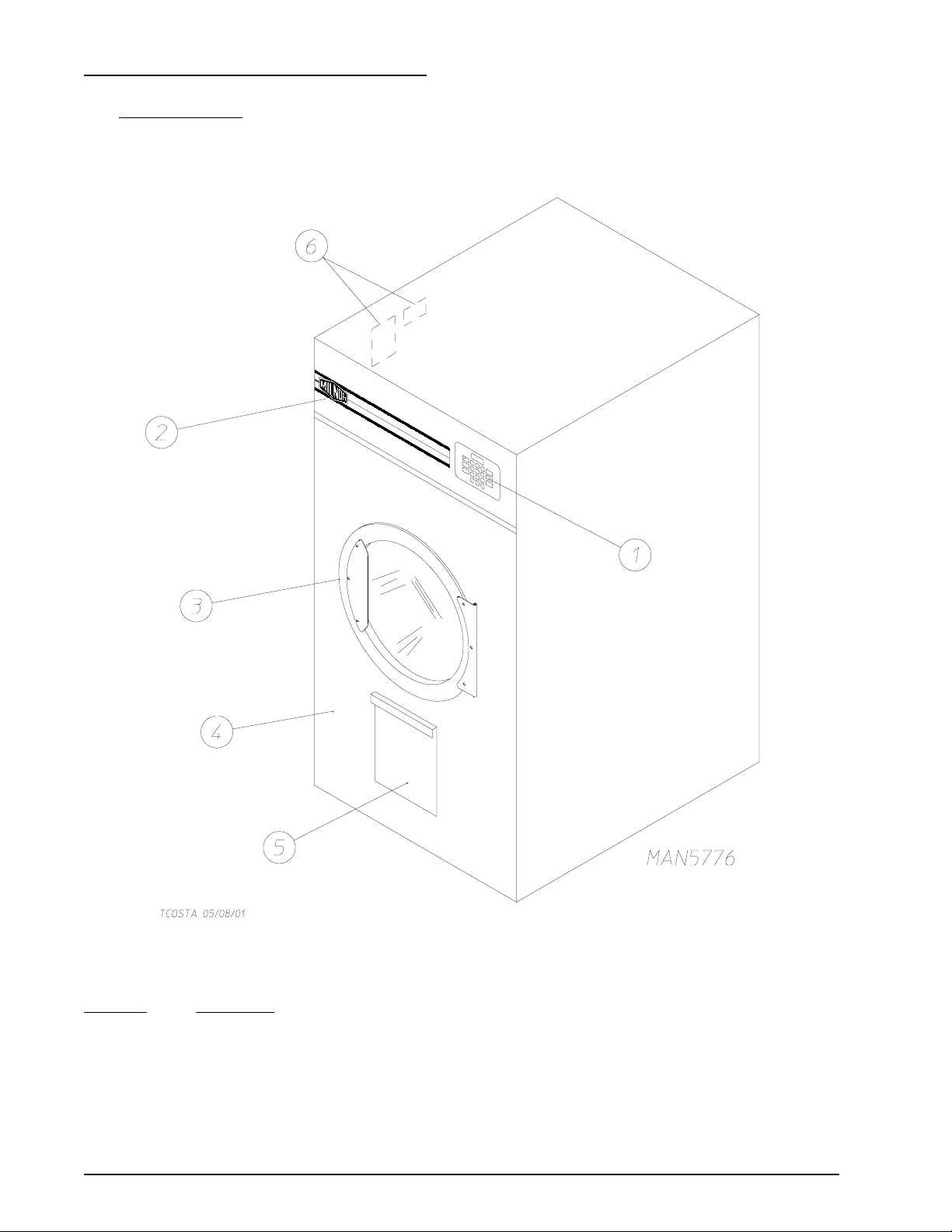
B. COMPONENT IDENTIFICATION
1. Dryer Front View
Illus. No. Description
1 Controls
2 Control (top access) Door Assembly
3 Main Door Assembly
4 Lint Compartment Area (lint screen located in lint drawer)
5 Lint Drawer
6 Data Label and Installation Label
6 American Dryer Corp. 113226- 6
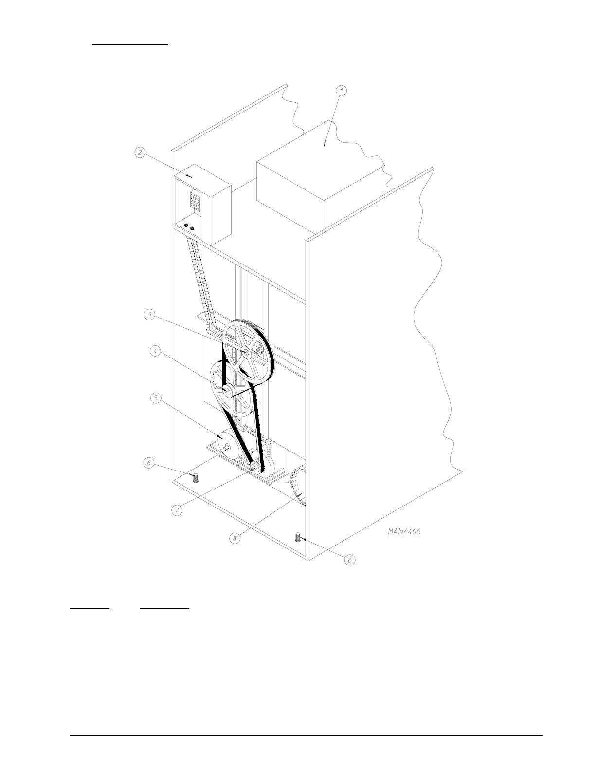
Dryer Rear View
2.
Illus. No. Description
1 Heating Unit
2 Electric Service Relay Box
3 Basket (tumbler) Bearing Mount Assembly
4 Idler Bearing Mount Assembly
5 Blower Motor Assembly (for reversing models only)
6 Leveling Legs (rear)
7 Basket (drive) Motor Assembly
8 Dryer Exhaust
113226- 6 www.amdry.com 7
SECTION III
INSTALLATION PROCEDURES
Installation should be performed by competent technicians in accordance with local and state codes. In the
absence of these codes, the installation must conform to applicable American National Standards: ANSI Z223.1LATEST EDITION (National Fuel Gas Code) or ANSI/NFPA NO. 70-LATEST EDITION (National Electrical
Code) or in Canada, the installation must conform to applicable Canadian Standards: CAN/CGA-B149.1-M91
(Natural Gas) or CAN/CGA-B149.2-M91 (Liquid Propane [L.P.] Gas) or LATEST EDITION (for General
Installation and Gas Plumbing) or Canadian Electrical Codes Parts 1 & 2 CSA C22.1-1990 or LATEST EDITION
(for Electrical Connections).
A. LOCATION REQUIREMENTS
Before installing the dryer, be sure the location conforms to local codes and ordinances. In the absence of such
codes or ordinances the location must conform with the National Fuel Gas Code ANSI.Z223.1 LATEST
EDITION, or in Canada, the installation must conform to applicable Canadian Standards: CAN/CGA-B149.1M91 (Natural Gas) or CAN/CGA-B149.2-M91 (L.P. Gas) or LATEST EDITION (for General Installation and
Gas Plumbing).
1. The dryer must be installed on a sound level floor capable of supporting its weight. Carpeting must be
removed from the floor area that the dryer is to rest on.
IMPORTANT: “The dryer must be installed on noncombustible floors only.”
2. The dryer must not be installed or stored in an area where it will be exposed to water and/or weather.
3. The dryer is for use in noncombustible locations.
4. Provisions for adequate air supply must be provided as noted in this manual (refer to Fresh Air Supply
Requirements in
5. Clearance provisions must be made from noncombustible construction as noted in this manual (refer to
Dryer Enclosure Requirements in
6. Provisions must be made for adequate clearances for servicing and for operation as noted in this manual
(refer to Dryer Enclosure Requirements in
7. Dryer must be exhausted to the outdoors as noted in this manual (refer to Exhaust Requirements in
Section E).
8. Dryer must be located in an area where correct exhaust venting can be achieved as noted in this manual
(refer to Exhaust Requirements in
Section D).
Section C).
Section C).
Section E).
9. The dryer must be installed with a proper exhaust duct connection to the outside.
10. The dryer must be installed with provisions for adequate combustion and make-up air supply.
CAUTION: This dryer produces combustible lint and must be exhausted to the outdoors. Every
6 months, inspect the exhaust ducting and remove any lint buildup.
8 American Dryer Corp. 113226- 6
IMPORTANT: Dryer should be located where a minimum amount of exhaust duct will be necessary.
IMPORTANT: Dryer must be installed in a location/environment, which the ambient
temperature remains between 40° F (4.44° C) and 130° F (54.44° C).
B. UNPACKING/SETTING UP
Remove protective shipping material (i.e., plastic wrap and/or optional shipping box) from dryer.
IMPORTANT: Dryer must be transported and handled in an upright position at ALL times.
The dryer can be moved to its final location while still attached to the skid or with the skid removed. To unskid
the dryer, locate and remove the two (2) bolts securing the base of the dryer to the wooden skid. One (1) is at
the rear base (remove the back panel for access), and the other is located in the bottom of the lint chamber. To
remove the bolt located in the lint chamber area, remove the lint drawer.
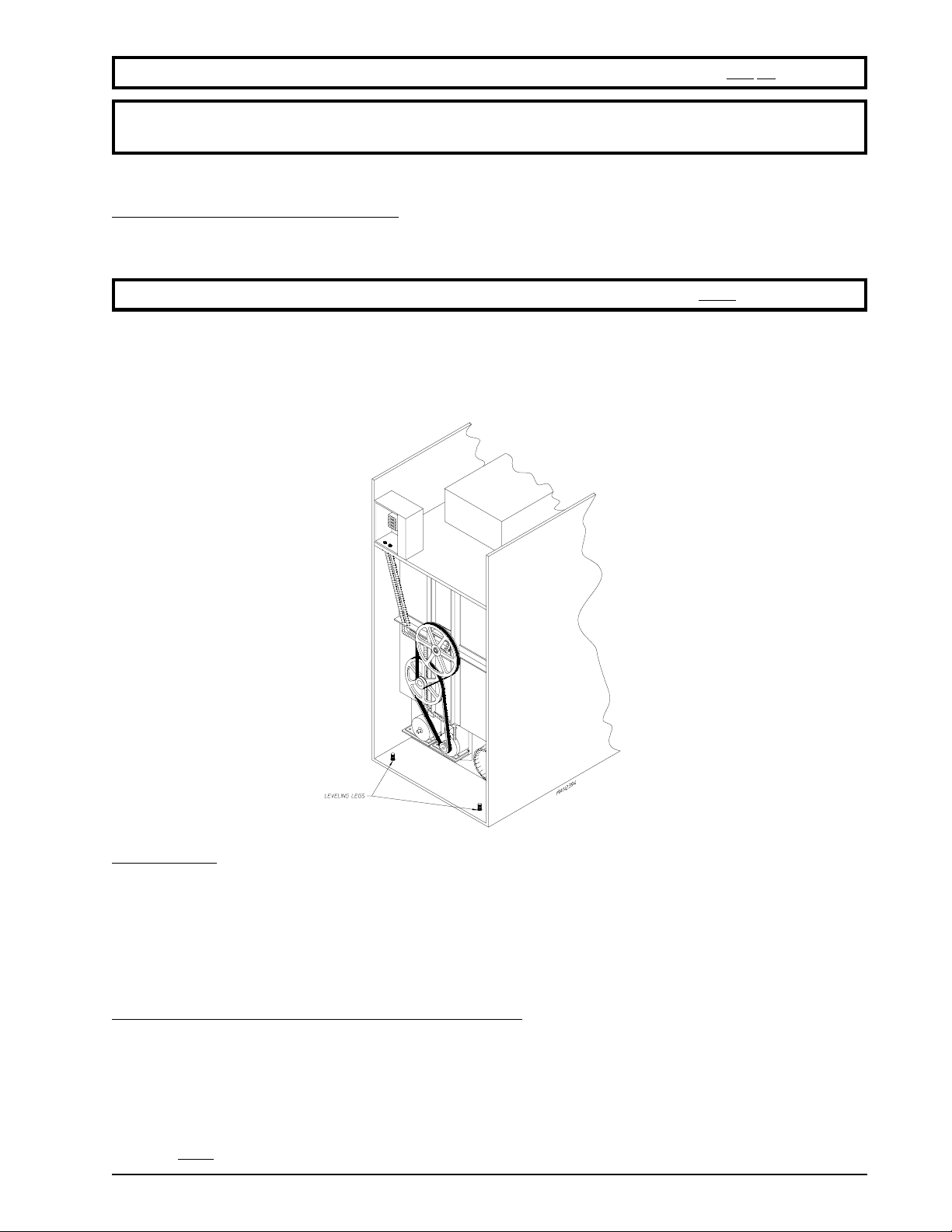
Leveling Dryer
The dryer is equipped with four (4) leveling legs, one (1) at each corner of the base. Two (2) are located at the
rear of the dryer base, and two (2) are located in the lint chamber (coop). To increase bearing life and improve
efficiency, the dryer should be tilted slightly to the rear.
C. DRYER ENCLOSURE REQUIREMENTS
Bulkheads and partitions should be made of noncombustible materials and must be located a minimum of
12-inches (30.48 cm), 18-inches (45.72 cm) or more is recommended for ease of installation, maintenance, and
service above the dryer’s outer top, except along the front of the dryer, which may be partially closed in if
desired. The clearance between the bulkhead header and the dryer must be a minimum of 4-inches (10.16 cm)
and must not extend more than 4-inches (10.16 cm) to the rear of the front. The bulkhead facing must not be
closed in
113226- 6 www.amdry.com 9
ALL the way to the top of the dryer. A 1-inch (2.54 cm) clearance is required.
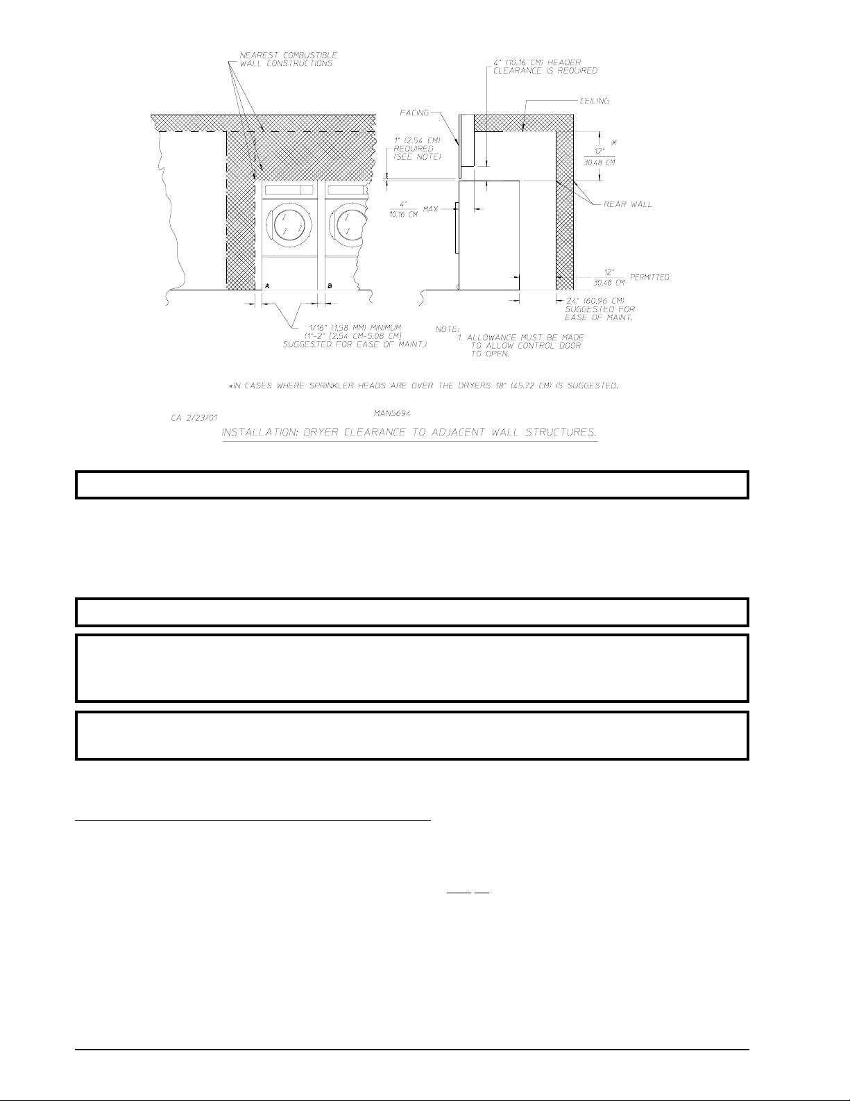
NOTE: Allowances must be made for the opening of the control door.
Dryers may be positioned sidewall to sidewall. However, a 1/16” (1.58 mm) minimum allowance must be made
for the opening and closing of the control door. It is suggested that the dryer be positioned about 2 feet (0.61
meters) away from the nearest obstruction for ease of installation, maintenance, and service (to be measured
from the back guard). Refer to the illustration above for details.
NOTE: Air considerations are important for proper and efficient operation.
IMPORTANT: Even though a minimum of only 12-inches (30.48 cm) is required, 24-inches
(60.96 cm) or more is suggested. The additional clearance is advantageous for ease
of installation and service.
IMPORTANT: When fire sprinkler systems are located above the dryers, a minimum of 18-inches
(45.72 cm) above the dryer console (module) is required.
D. FRESH AIR SUPPLY REQUIREMENTS
When the dryer is operating, it draws in room air, heats it, passes this air through the basket (tumbler), and
exhausts it out of the building. Therefore, the room air must be continually replenished from the outdoors. If the
make-up air is inadequate, drying time and drying efficiency
sail switch “fluttering” problems may result, as well as premature motor failure from overheating.
will be adversely affected. Ignition problems and
Air supply (make-up air) must be given careful consideration to ensure proper performance of each dryer. An
unrestricted source of air is necessary for each dryer. An airflow of 1,000 cfm (cubic feet per minute),
(28.3 cmm [cubic meters per minute]) must be supplied to each dryer. As a general rule, an unrestricted air
entrance from the outdoors (atmosphere) of a minimum of 1-1/2 square feet (0.14 square meters) is required for
each dryer. (Calculation based on 1 inch
installed with provisions for adequate combustion and make-up air supply.
10 American Dryer Corp. 113226- 6
2
[6.4516 cm2] per 1,000 Btu [251.9958 kcal].) The dryer must be
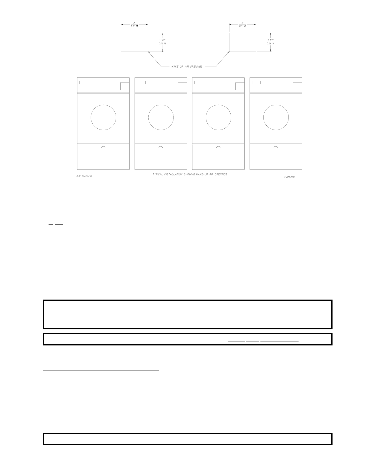
To compensate for the use of registers or louvers used over the openings, these make-up air openings must be
increased by approximately thirty-three percent (33%). Make-up air openings should not be located in an area
directly near where exhaust vents exit the building.
is not necessary to have a separate make-up air opening for each dryer. Common make-up air openings are
It
acceptable. However, they must be set up in such a manner that the make-up air is distributed equally to
the dryers.
ALL
EXAMPLE: For a bank of four (4) dryers, two (2) unrestricted openings measuring 2 feet by 1-1/2 feet (0.61
meters by 0.46 meters) are acceptable. (Calculation based on 1 inch
[251.9958 kcal].)
Allowances must be made for remote or constricting passageways or where dryers are located at excessive
altitudes or predominantly low pressure areas.
2
[6.4516 cm2] per 1,000 Btu
IMPORTANT: Make-up air must be provided from a source free of dry cleaning solvent fumes.
Make-up air that is contaminated by dry cleaning solvent fumes will result in
irreparable damage to the motors and other dryer components.
NOTE: Component failure due to dry cleaning solvent fumes will VOID THE WARRANTY.
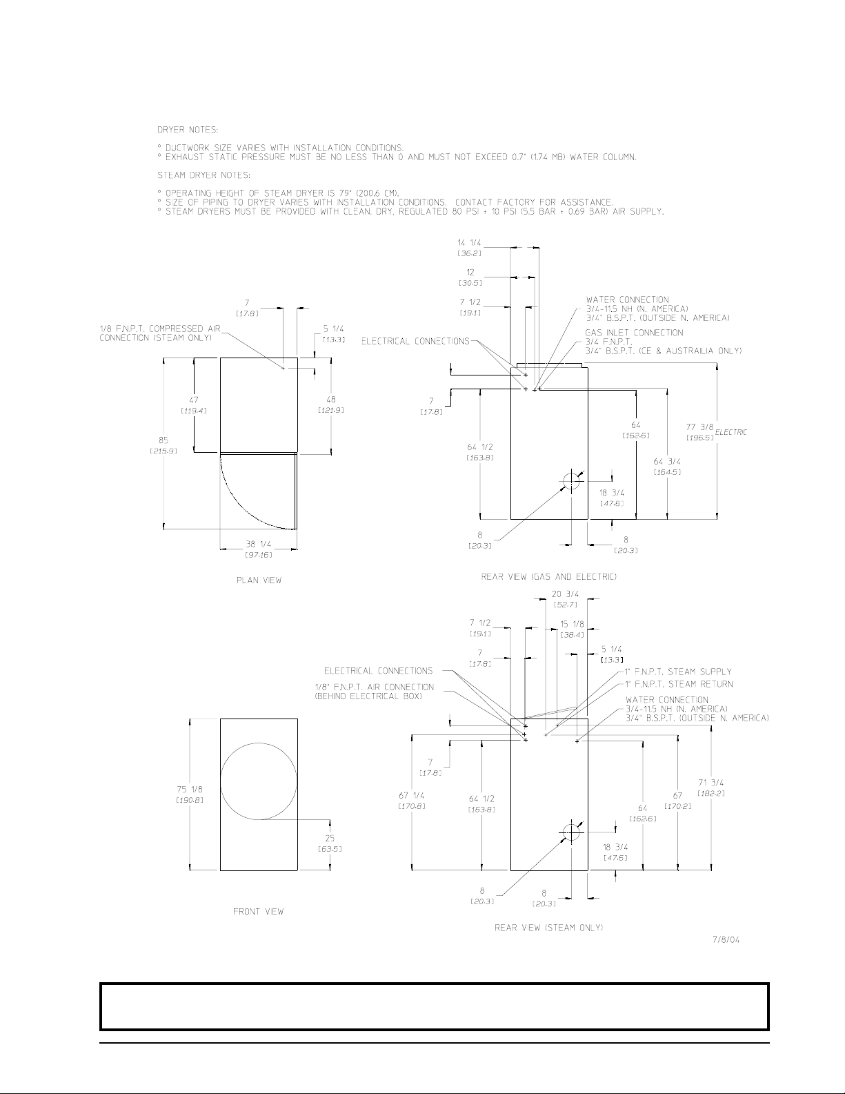
E. EXHAUST REQUIREMENTS
1. General Exhaust Ductwork Information
Exhaust ductwork should be designed and installed by a qualified professional. Improperly sized ductwork
will create excessive back pressure, which results in slow drying, increased use of energy, overheating of
the dryer, and shutdown of the burner by the airflow (sail) switches, burner hi-limits, or basket (tumbler)
hi-limits. The dryer must be installed with a proper exhaust duct connection to the outside.
CAUTION: This dryer produces combustible lint and must be exhausted to the outdoors.
113226- 6 www.amdry.com 11
CAUTION: IMPROPERLY SIZED OR INSTALLED EXHAUST DUCTWORK CAN
CREATE A POTENTIAL FIRE HAZARD.
The ductwork should be laid out in such a way that the ductwork travels as directly as possible to the
outdoors with as few turns as possible. Single or independent dryer venting is recommended.
Horizontal Venting:
When single dryer venting is used, the length of ductwork from the dryer to the outside exhaust outlet must
not exceed 25 feet (7.62 meters). The minimum diameter of this ductwork must be at least 8-inches
(20.32 cm). In the case of multiple (common) dryer venting, the distance from the last dryer to the outside
exhaust outlet must not exceed 15 feet (4.57 meters). The shape of the ductwork
as the minimum cross-sectional area is provided. It is suggested that the use of 90° turns
30° and/or 45° angles instead. The radius of the elbows should preferably be 1-1/2 times the diameter of
the duct. Including basket (tumbler)/dryer elbow connections or elbows used for outside protection from
the weather, no more than one (1) elbow should be used in the exhaust duct run. If more than one (1)
elbow is used, the cross-sectional area of the ductwork must be increased.
smooth inside with no projections from sheet metal screws or other obstructions, which will collect lint.
When adding ducts, the duct to be added should overlap the duct to which it is to be connected.
ductwork joints must be taped to prevent moisture and lint from escaping into the building. Inspection
doors should be installed at strategic points in the exhaust ductwork for periodic inspection and cleaning of
lint from the ductwork.
is not critical as long
be avoided; use
ALL ductwork should be
ALL
Vertical Venting:
When single dryer venting is used, the length of the ductwork from the dryer to the outside exhaust outlet
must not exceed 15 feet (4.57 meters). The minimum diameter of this ductwork must be at least
8-inches (20.32 cm). In the case of multiple (common) dryer venting, the distance from the last dryer to the
outside exhaust outlet must not exceed 15 feet (4.57 meters). The shape of the ductwork
long as the minimum cross-sectional area is provided. It is suggested that the use of 90° turns
be avoided; use 30° and/or 45° bends instead. The radius of the elbows should preferably be 1-1/2 times
the diameter of the duct.
screws or other obstructions, which will collect lint. When adding ducts, the duct to be added should
overlap the duct to which it is to be connected.
and lint from escaping into the building. Inspection doors should be installed at strategic points in the
exhaust ductwork for periodic inspection and cleaning of lint from the ductwork.
ALL ductwork should be smooth inside with no projections from sheet metal
ALL ductwork joints must be taped to prevent moisture
is not critical as
IMPORTANT: It is recommended that exhaust or booster fans not be used in the exhaust ductwork
system.
IMPORTANT: Exhaust back pressure measured by a manometer in the exhaust duct must be no less
than 0 and must not exceed 0.7 inches (1.74 mb) of water column (W.C.).
NOTE: When the exhaust ductwork passes through a wall, ceiling, or roof made of combustible
materials, the opening must be 2-inches (5.08 cm) larger than the duct (all the way around).
The duct must be centered within this opening.
Outside Ductwork Protection
To protect the outside end of the horizontal ductwork from the weather, a 90° elbow bent downward
should be installed where the exhaust exits the building. If the ductwork travels vertically up through the
roof, it should be protected from the weather by using a 180° turn to point the opening downward. In
either case, allow at least twice the diameter of the duct between the duct opening and the nearest obstruction.
12 American Dryer Corp. 113226- 6
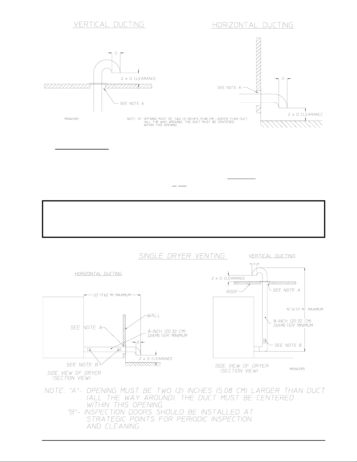
2. Single Dryer Venting
When possible, it is suggested to provide a separate exhaust duct for each dryer. The exhaust duct should
be laid out in such a way that the ductwork travels as directly as possible to the outdoors with as few turns
as possible. It is suggested that the use of 90° turns in the ducting
instead. The shape of the exhaust ductwork
provided.
is not critical as long as the minimum cross section area is
be avoided; use 30° and/or 45° angles
NOTE: As per the National Fuel Gas Code, “Exhaust ducts for type 2 clothes dryers shall be
constructed of sheet metal or other noncombustible material. Such ducts shall be equivalent in
strength and corrosion resistance to ducts made of galvanized sheet steel not less than 26
gauge (0.0195 inches [0.50 mm]) thick.”
113226- 6 www.amdry.com 13
 Loading...