

American Dryer D3030 User Manual
D3030 Installation Manual
(DSI/Phase 7 with S.A.F.E.)
W ARNING: For your safety the information in
this manual must be followed to minimize the risk
of fire or explosion or to prevent property
damage, personal injury or death.
— Do not store or use gasoline or other flammable
vapors and liquids in the vicinity of this or any
other appliance.
— WHA T TO DO IF YOU SMELL GAS:
• Do not try to light any appliance.
• Do not touch any electrical switch; do not
use any phone in your building.
• Clear the room, building or area of all
occupants.
• Immediately call your gas supplier from a
neighbor’s phone. Follow the gas supplier’s
instructions.
• If you cannot reach your gas supplier, call
the fire department.
— Installation and service must be performed by a
qualified installer, service agency or the gas
supplier .
AVERTISSEMENT: Assurez-vous de bien
suivre les instructions données dans cette notice
pour réduire au minimum le risque d’incendie
ou d’explosion ou pour éviter tout dommage
matériel, toute blessure ou la mort.
— Ne pas entreposer ni utiliser d’essence ni
d’autres vapeurs ou liquides inflammables à
proximité de cet appareil ou de tout autre
appareil.
— QUE F AIRE SI VOUS SENTEZ UNE ODEUR
DE GAZ:
• Ne pas tenter d’allumer d’appareils.
• Ne touchez à aucun interrupteur. Ne pas
vous servir des téléphones se trouvant dans
le bâtiment.
• Évacuez la pièce, le bâtiment ou la zone.
• Appelez immédiatement votre fournisseur
de gaz depuis un voisin. Suivez les
instructions du fournisseur .
• Si vous ne pouvez rejoindre le fournisseur
de gaz, appelez le service des incendies.
— L ’installation et l’entretien doivent être assurés par
un installateur ou un service d’entretien qualifié
ou par le fournisseur de gaz.
JLA Limited
Meadowcroft Lane, Halifax Road
Ripponden
W est Y orkshire, England
HX6 4AJ
Telephone: 01422 822282 / Fax: 01422 824390
Part No. 113338
Retain This Manual In A Safe Place For Future Reference
This product embodies advanced concepts in engineering, design, and safety. If this product is properly maintained, it will
provide many years of safe, efficient, and trouble free operation.
ONLY qualified technicians should service this equipment.
OBSERVE ALL SAFETY PRECAUTIONS displayed on the equipment or specified in the installation manual included with
the dryer.
The following “FOR YOUR SAFETY” caution must be posted near the dryer in a prominent location.
FOR YOUR SAFETY
Do not store or use gasoline or
other flammable vapors and
liquids in the vicinity of this or
any other appliance.
W e have tried to make this manual as complete as possible and hope you will find it useful. Manufacturer reserves the right
to make changes from time to time, without notice or obligation, in prices, specifications, colors, and material, and to change
or discontinue models. The illustrations included in this manual may not depict your particular dryer exactly.
POUR VOTRE SÉCURITÉ
Ne pas entreposer ni utiliser d’essence
ni d’autres vapeurs ou liquides
inflammables à proximité de cet
appareil ou de tout autre appareil.
Important
For your convenience, log the following information:
DA TE OF PURCHASE________________________________________________________ MODEL NO. __________________
DISTRIBUTOR’S NAME ____________________________________________________________________________________
Serial Number(s) ________________________________________________________________________________________
D3030
________________________________________________________________________________________
________________________________________________________________________________________
Replacement parts can be obtained from your distributor or JLA. When ordering replacement parts from JLA, you can F AX
your order to JLA at 01422 824390 or telephone your order directly to the JLA Parts Department at 01422 822282. Please
specify the dryer model number and serial number in addition to the description and part number, so that your order is
processed accurately and promptly.
“IMPORT ANT NOTE TO PURCHASER”
Information must be obtained from your local gas supplier on the instructions
to be followed if the user smells gas. These instructions must be posted in a
prominent location near the dryer.
IMPORTANT
YOU MUST DISCONNECT AND LOCKOUT THE ELECTRIC SUPPL Y AND THE GAS
SUPPLY OR THE STEAM SUPPLY BEFORE ANY COVERS OR GUARDS ARE
REMOVED FROM THE MACHINE TO ALLOW ACCESS FOR CLEANING,
ADJUSTING, INSTALLATION, OR TESTING OF ANY EQUIPMENT PER OSHA
(Occupational Safety and Health Administration) STANDARDS.
«Attention: Au moment de l’entretien des
“Caution: Label all wires prior to
disconnection when servicing controls. W iring
errors can cause improper operation.”
commandes, étiquetez tous les fils avant de
les débrancher. Des erreurs de câblage
peuvent entraîner un fonctionnement
inadéquat et dangereux.»
CAUTION
DRYERS SHOULD NEVER BE LEFT UNA TTENDED WHILE IN OPERA TION.
WARNING
CHILDREN SHOULD NOT BE ALLOWED TO PLA Y ON OR NEAR THE DRYER(S).
CHILDREN
SHOULD BE SUPER VISED IF NEAR DR YERS IN OPERATION.
FOR YOUR SAFETY
DO NOT DR Y MOP HEADS IN THE DRYER.
DO NOT USE DR YER IN THE PRESENCE OF DR Y CLEANING FUMES.
WARNING
UNDER NO CIRCUMSTANCES should the dryer door switch or the heat circuit
devices ever be disabled.
WARNING
The dryer must never be operated with any of the back guards, outer tops, or service
panels removed. PERSONAL INJURY OR FIRE COULD RESUL T .
WARNING
DRYER MUST NEVER BE OPERA TED WITHOUT THE LINT FIL TER/SCREEN IN
PLACE, EVEN IF AN EXTERNAL LINT COLLECTION SYSTEM IS USED.
IMPORTANT
PLEASE OBSERVE ALL SAFETY PRECAUTIONS displayed on the equipment and/or
specified in the installation manual included with the dryer.
Dryers must not be installed or stored in an area where it
The wiring diagram for the dryer is located in the front electrical control box area.
will be exposed to water or weather .

Table of Contents
SECTION I
IMPORTANT INFORMATION ...............................................................................3
A. Receiving and Handling ............................................................................................................... 3
B. Safety Precautions ...................................................................................................................... 4
SECTION II
SPECIFICATIONS.....................................................................................................6
A. Specifications ............................................................................................................................. 6
SECTION III
INSTALLATION PROCEDURES ........................................................................... 8
A. Unpacking/Setting Up ................................................................................................................. 8
B. Location Requirements ............................................................................................................... 9
C. Dryer Enclosure Requirements .................................................................................................. 10
D. Fresh Air Supply Requirements ................................................................................................. 11
E. Exhaust Requirements ............................................................................................................... 12
F. Electrical Information ................................................................................................................ 18
G . Gas Information ........................................................................................................................ 24
H. Steam Information .................................................................................................................... 28
I. Preparation For Operation/Start-Up ......................................................................................... 33
J. Preoperational T ests ................................................................................................................. 34
K. Preoperational Instructions ........................................................................................................ 35
L. Shut Down Instructions ............................................................................................................. 37
SECTION IV
SERVICE/PARTS INFORMATION ...................................................................... 3 8
A. Service ..................................................................................................................................... 38
B. Parts ........................................................................................................................................ 38
SECTION V
WARRANTY INFORMATION ............................................................................... 39
A. Returning W arranty Cards......................................................................................................... 39
B. Warranty .................................................................................................................................. 39
SECTION VI
ROUTINE MAINTENANCE .................................................................................. 4 0
A. Cleaning ................................................................................................................................... 40
B. Adjustments ............................................................................................................................. 41
C. Lubrication ............................................................................................................................... 41

SECTION VII
DATA LABEL INFORMATION............................................................................. 4 2
A. Data Label ............................................................................................................................... 42
SECTION VIII
REVERSING TIMER SPIN/DWELL ADJUSTMENTS ..................................... 44
SECTION IX
OPL SENSOR ACTIVATED FIRE EXTINGUISHING (S.A.F.E.) SYSTEM .. 4 5
Installation ...................................................................................................................................... 46
W ater Connection........................................................................................................................... 47
S.A.F .E. Theory of Operation......................................................................................................... 49
Parts Break Down .......................................................................................................................... 50
SECTION X
COIN SENSOR ACTIVATED FIRE EXTINGUISHING (S.A.F.E.) SYSTEM 5 2
Installation ...................................................................................................................................... 53
W ater Connection........................................................................................................................... 54
S.A.F .E. Theory of Operation......................................................................................................... 56
Parts Break Down .......................................................................................................................... 57
SECTION I
IMPORTANT INFORMATION
A. RECEIVING AND HANDLING
The dryer is shipped in a protective stretch wrap cover with protective cardboard corners and top cover (or
optional box) as a means of preventing damage in transit. Upon delivery , the dryer and packaging, and wooden
skid should be visually inspected for shipping damage. If any damage whatsoever is noticed, inspect further
before delivering carrier leaves.
Dryers damaged in shipment:
1.
ALL dryers should be inspected upon receipt and before they are signed for.
2. If there is suspected damage or actual damage, the trucker ’s receipt should be so noted.
3. If the dryer is damaged beyond repair, it should be refused. Those dryers, which were not damaged in a
damaged shipment, should be accepted, but the number received and the number refused must be noted
on the receipt.
4. If you determine that the dryer was damaged after the trucker has left your location, you should call the
delivering carrier’s freight terminal immediately and file a claim. The freight company considers this
concealed damage. This type of freight claim is very difficult to get paid and becomes extremely difficult
when more than a day or two passes after the freight was delivered. It is your responsibility to file freight
claims. Dryer/parts damaged in transit cannot be claimed under warranty.
5. Freight claims are the responsibility of the consignee, and ALL claims must be filed at the receiving end.
JLA assumes no responsibility for freight claims or damages.
6. If you need assistance in handling the situation, please contact the JLA Traffic Manager at 01422
822282.
IMPORTANT: The dryer must be transported and handled in an upright position at ALL times.
3

B. SAFETY PRECAUTIONS
WARNING: For your safety, the information in this manual must be followed to minimize the risk of
fire or explosion or to prevent property damage, personal injury , or loss of life.
WARNING: The dryer must never be operated with any of the back guards, outer tops, or
service panels removed. PERSONAL INJURY OR FIRE COULD RESUL T.
1. DO NOT store or use gasoline or other flammable vapors and liquids in the vicinity of this or any other
appliance.
2. Purchaser/user should consult the local gas supplier for proper instructions to be followed in the event the
user smells gas. The instructions should be posted in a prominent location.
3. WHAT TO DO IF YOU SMELL GAS...
a. DO NOT try to light any appliance.
b. DO NOT touch any electrical switch.
c. DO NOT use any phone in your building.
d. Clear the room, building, or area of ALL occupants.
e. Immediately call your gas supplier from a neighbor’ s phone. Follow the gas supplier’s instructions.
f. If you cannot reach your gas supplier, call the fire department.
4. Installation and service must be performed by a qualified installer, service agency, or gas supplier.
5. Dryer(s) must be exhausted to the outdoors.
6. Although JLA produces a very versatile dryer, there are some articles that, due to fabric composition or
cleaning method, should not be dried in it.
WARNING: Dry only water washed fabrics. DO NOT dry articles spotted or washed in dry
cleaning solvents, a combustible detergent, or “all purpose” cleaner .
EXPLOSION COULD RESUL T.
WARNING: DO NOT dry rags or articles coated or contaminated with gasoline, kerosene, oil, paint,
or wax.
EXPLOSION COULD RESUL T.
4
WARNING: DO NOT dry mop heads. Contamination by wax or flammable solvents will create a
fire hazard.
WARNING: DO NOT use heat for drying articles that contain plastic, foam, sponge rubber , or
similarly textured rubber materials. Drying in a heated basket (tumbler) may damage
plastics or rubber and may be a fire hazard.
7. A program should be established for the inspection and cleaning of lint in the burner area, exhaust ductwork,
and area around the back of the dryer. The frequency of inspection and cleaning can best be determined
from experience at each location.
WARNING: The collection of lint in the burner area and exhaust ductwork can create a potential fire
hazard.
8. For personal safety, the dryer must be electrically grounded in accordance with local codes and/or the
National Electrical Code ANSI/NFPA NO. 70-LATEST EDITION or in Canada, the Canadian Electrical
Codes Parts 1 & 2 CSA C22.1-1990 or LATEST EDITION.
NOTE: Failure to do so will VOID THE WARRANTY.
9. UNDER NO CIRCUMSTANCES should the dryer door switch or the heat circuit devices ever be
disabled.
WARNING: PERSONAL INJURY OR FIRE COULD RESUL T .
10. This dryer is not to be used in the presence of dry cleaning solvents or fumes.
11. Remove articles from the dryer as soon as the drying cycle has been completed.
WARNING: Articles left in the dryer after the drying and cooling cycles have been completed can
create a fire hazard.
12. READ AND FOLLOW ALL CAUTION AND DIRECTION LABELS ATTACHED TO THE
DRYER.
13. For safety, proper operation, and optimum performance, the dryer must not be operated with a load less
than sixty-six percent (66%), 20 lb (9 kg) of its rated capacity.
WARNING: YOU MUST DISCONNECT AND LOCKOUT THE ELECTRIC SUPPLY AND
THE GAS SUPPL Y OR THE STEAM SUPPL Y BEFORE ANY COVERS OR
GUARDS ARE REMOVED FROM THE MACHINE TO ALLOW ACCESS
FOR CLEANING , ADJUSTING, INST ALLA TION, OR TESTING OF ANY
EQUIPMENT PER OSHA (Occupational Safety and Health Administration)
STANDARDS.
5
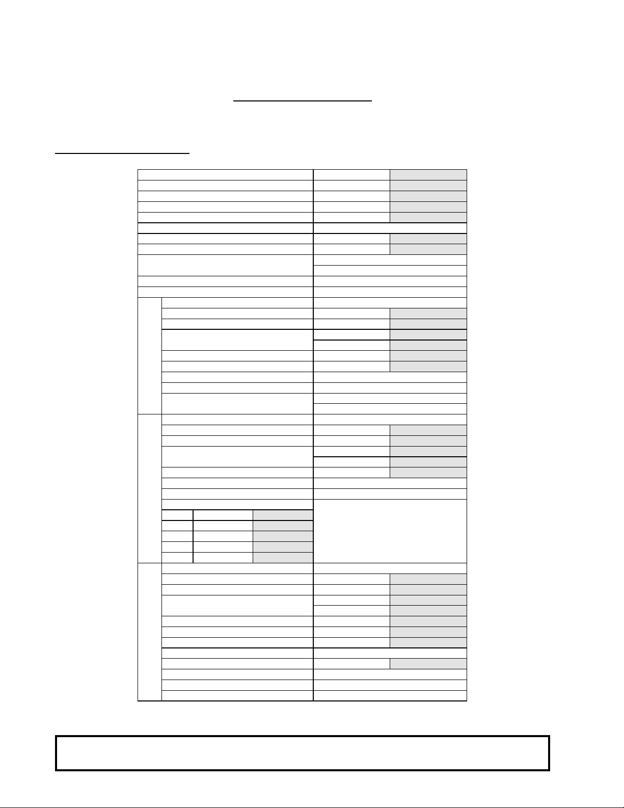
A. SPECIFICATIONS
SECTION II
SPECIFICATIONS
MAXIMUM CAPA CITY (DRY WEIGHT) 3 0 lb
TUMBLER DIAMETER 30 ”
TUMB LER DEPTH 30 ”
TUMBLER VOLUME 12.27 cu ft
TUMBLER/DRIVE MOTOR 1 /2 hp
BLOWER/FAN MOTOR N / A
DOOR OPENING (DIAMETER) 21-1/2”
DOOR SILL HEIGHT 31-1/2”
WATER CONNECTION 3/ 4”- 11.5 NH
3/4” B.S.P.T. (Outside North America)
DRYERS P ER 20’/40’ CONTAINER 1 2 / 28
DRYERS PER 48’/53’ TRUCK 32 / 36
VOLTAGE AVAILABLE 120-460V 1,3ø 50/60 Hz
APPROXIMATE NET WEIGHT 535 lb
APPROXIMATE SHIPPING WEIGHT 585 lb
AIRFLOW
HEAT INPUT 95,000 Btu/hr
EXHAUS T CONNECTION (DIAMETER) 8”
Gas
COMPRESSED AIR CONNECTION N / A
COMPRESSED AIR VOLUME N / A
INLET PIPE CONNECTION 1/2 ” F.B.S.P.T.
VOLTAGE AVAILABLE 208-460V 1,3ø 2,3,4w 50/60 Hz
APPROXIMATE NET WEIGHT 535 lb
APPROXIMATE SHIPPING WEIGHT 585 lb
AIRFLOW
EXHAUS T CONNECTION (DIAMETER) 8”
COMPRESSED AIR CONNECTION N / A
COMPRESSED AIR VOLUME N / A
OVEN SIZE
kW Btu/hr
Electric
15 51,200
20 68,300
24 81,900
30 102,400
VOLTAGE AVAILABLE 120-460V 1,3ø 50/60 Hz
APPROXIMATE NET WEIGHT 580 lb
APPROXIMATE SHIPPING WEIGHT 630 lb
AIRFLOW
STEAM CONSUMPTION 104 lb/hr
OPERATING STEAM PRESSURE 12 5 psi m ax
EXHAUS T CONNECTION (DIAMETER) 8”
COMPRESSED AIR CONNECTION 1/8 ” F.N.P.T.
Steam
COMPRESSED AIR VOLUME 0.5 cfh
BOILER HORSE POWER (NORMAL LOAD) 3. 0 Bhp
SUPPLY CONNECTION 1” F.N.P.T.
RETUR N CONNE CTION 1” F.N.P.T.
Shaded areas are stated in metric equivalents
kcal/hr
12,900
17,200
20,600
25,800
60 Hz
50 Hz
60 Hz
50 Hz
60 Hz
50 Hz
600 cfm
500 cfm
1/2” B.S.P.T.
600 cfm
500 cfm
600 cfm
500 cfm
(North America)
23,940 kcal/hr
(CE and Australia Only)
13.6 kg
76.2 cm
76.2 cm
347.45 L
0.373 kW
54.61 cm
80.01 cm
242.7 kg
265.4 kg
17 cmm
14.16 cmm
20.3 cm
242.7 kg
265.4 kg
17 cmm
14.16 cmm
20.3 cm
263.1 kg
285.8 kg
17 cmm
14.16 cmm
47.2 kg/hr
8.6 bar
20.3 cm
0.01 cmh
NOTE: Manufacturer reserves the right to make changes in specifications at any time without notice or
obligation.
6
Specifications
NOTE: Manufacturer reserves the right to make changes in specifications at any time without notice or
obligation.
7
SECTION III
INSTALLATION PROCEDURES
Installation should be performed by competent technicians in accordance with local and state codes. In the
absence of these codes, the installation must conform to applicable American National S tandards: ANSI Z223.1LATEST EDITION (National Fuel Gas Code) or ANSI/NFPA NO. 70-LATEST EDITION (National Electrical
Code) or in Canada, the installation must conform to applicable Canadian Standards: CAN/CGA-B149.1-M91
(Natural Gas) or CAN/CGA-B149.2-M91 (Liquid Propane [L.P.] Gas) or LATEST EDITION (for General
Installation and Gas Plumbing) or Canadian Electrical Codes Parts 1 & 2 CSA C22.1-1990 or LATEST EDITION
(for Electrical Connections).
A. UNPACKING/SETTING UP
Remove protective shipping material (i.e., plastic wrap and optional shipping box) from dryer.
IMPORTANT: Dryer must be transported and handled in an upright position at ALL times.
The dryer can be moved to its final location while still attached to the skid or with the skid removed. T o unskid
the dryer, locate and remove the four (4) bolts securing the base of the dryer to the wooden skid. Two (2) are
at the rear base (remove the back panel for access), and two (2) are located in the bottom of the lint chamber.
T o remove the two (2) bolts located in the lint chamber area, remove the lint door.
With the skid removed, to make it easier to slide the dryer into its final position, slightly lower ALL four (4)
leveling legs, so that the dryer will slide on the legs instead of the base frame.
T o increase bearing life and improve efficiency, the dryer should be tilted slightly to the rear.
The lint coops of ALL D3030 model dryers are supported during shipping by a bracket. REMOVE THIS
BRACKET BEFORE STARTING THE DRYER.
1. Leveling Dryer
The dryer is equipped with four (4) leveling legs, one (1) at each corner of the base. Two (2) are located
at the rear of the dryer base, and two (2) are located in the lint chamber (coop). To increase bearing life
and improve efficiency , the dryer should be tilted slightly to the rear.
8
B. LOCATION REQUIREMENTS
Before installing the dryer, be sure the location conforms to local codes and ordinances. In the absence of such
codes or ordinances the location must conform with the National Fuel Gas Code ANSI.Z223.1 LATEST
EDITION, or in Canada, the installation must conform to applicable Canadian Standards: CAN/CGA-B149.1-
M91 (Natural Gas) or CAN/CGA-B149.2-M91 (Liquid Propane [L.P .] Gas) or LATEST EDITION (for General
Installation and Gas Plumbing).
1. The dryer must be installed on a sound level floor capable of supporting its weight. Carpeting must be
removed from the floor area that the dryer is to rest on.
IMPORTANT: “The dryer must be installed on noncombustible floors only.”
2. The dryer must not be installed or stored in an area where it will be exposed to water and/or weather.
3. The dryer is for use in noncombustible locations.
4. Provisions for adequate air supply must be provided as noted in this manual (refer to Fresh Air Supply
Requirements in
5. Clearance provisions must be made from combustible construction as noted in this manual (refer to Dryer
Enclosure Requirements in Section C).
Section D).
6. Provisions must be made for adequate clearances for servicing and for operation as noted in this manual
(refer to Dryer Enclosure Requirements in Section C).
7. Dryer must be exhausted to the outdoors as noted in this manual (refer to Exhaust Requirements in
Section E).
8. Dryer must be located in an area where correct exhaust venting can be achieved as noted in this manual
(refer to Exhaust Requirements in Section E).
IMPORTANT: Dryer should be located where a minimum amount of exhaust duct will be necessary.
9. The dryer must be installed with a proper exhaust duct connection to the outside.
10. The dryer must be installed with provisions for adequate combustion and make-up air supply .
CAUTION: This dryer produces combustible lint and must be exhausted to the outdoors. Every 6
months, inspect the exhaust ducting and remove any lint build up.
9
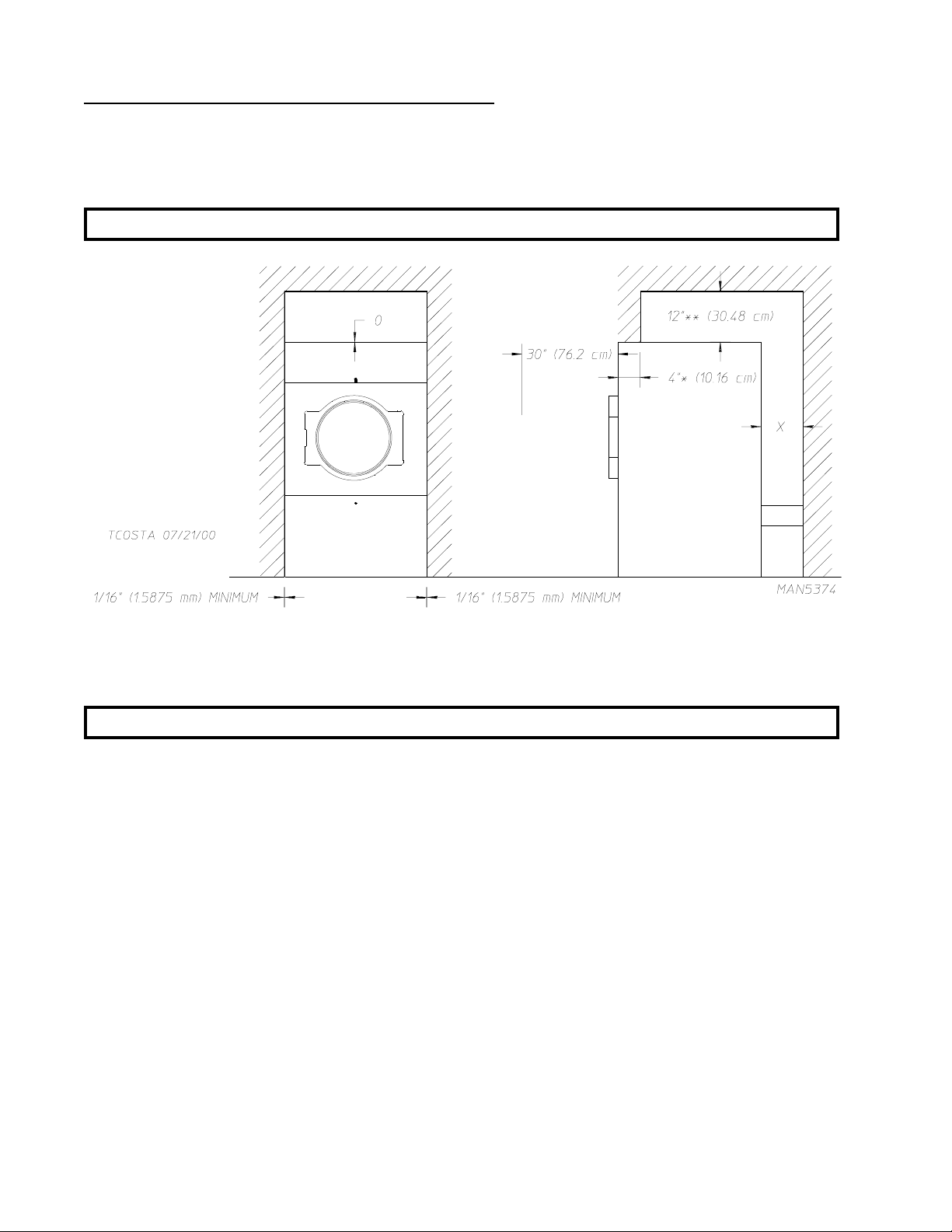
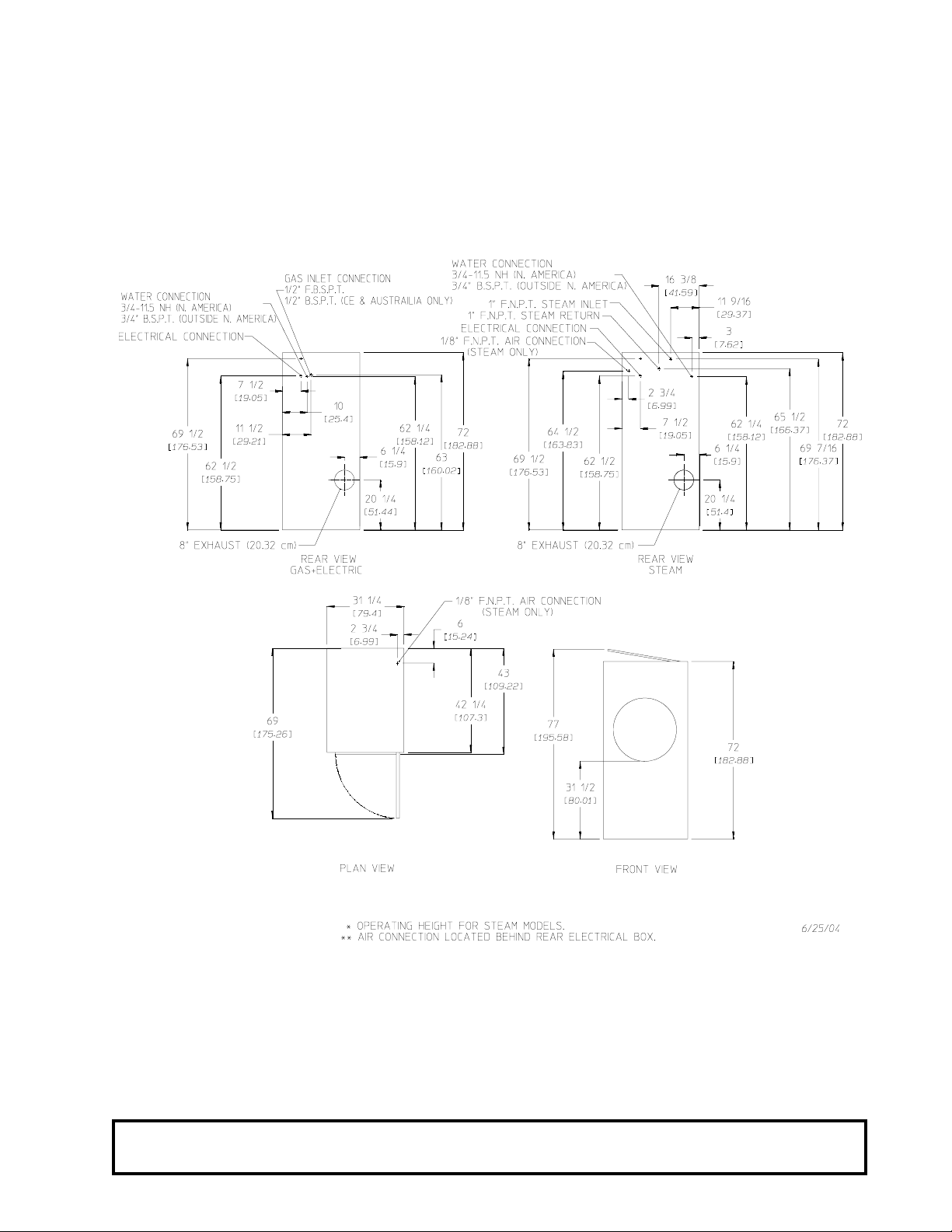
C. DRYER ENCLOSURE REQUIREMENTS
Bulkheads and partitions should be made of noncombustible materials and must be located a minimum of
12-inches (30.48 cm) above the dryer’s outer top; 18-inches (45.72 cm) for steam dryers, except along the front
of the dryer which may be closed if desired.
NOTE: Allowances must be made for opening the control door .
X = 12-inch (30.48 cm) minimum, 24-inches (60.96 cm) is suggested for ease of maintenance.
* 1-inch (2.54 cm) maximum for electric dryers.
** 18-inch (45.72 cm) minimum for steam dryers.
NOTE: Air considerations are important for proper and efficient operation.
Dryers may be positioned sidewall to sidewall. However, a 1/16” (1.5875 mm) minimum allowance must be
made for the opening and closing of the control door and the lint door. It is suggested that the dryer be positioned
about 2 feet (0.61 meters) away from the nearest obstruction for ease of installation, maintenance, and service
(to be measured from the back guard). Refer to the illustration above for details.
10
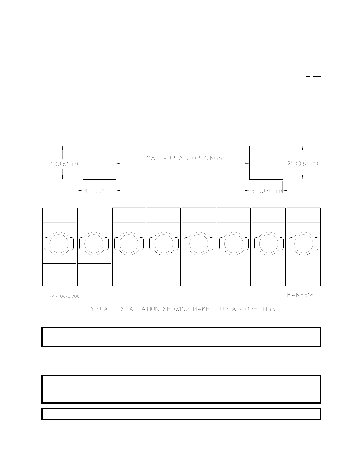
D. FRESH AIR SUPPLY REQUIREMENTS
The D3030 air supply (make-up air) must be given careful consideration to assure proper performance of each
dryer. An unrestricted source of air is necessary for each dryer. As a general rule, an unrestricted air entrance
from the outdoors (atmosphere) of a minimum of 1-1/2 square feet (0.14 square meters) is required for each
dryer. If registers or louvers are installed over the openings, then the area must be increased. It
necessary to have a separate make-up air opening for each dryer. Common make-up air openings are acceptable.
However, they must be set up in such a manner that the make-up air is distributed equally to the dryers. The
dryer must be installed with provisions for adequate combustion and make-up air supply.
EXAMPLE: For a bank of eight (8) dryers, two (2) unrestricted openings measuring 2 feet by 3
feet (0.61 meters by 0.91 meters), (6 square feet [0.56 square meters]) are
acceptable.
is not
IMPORTANT: Make-up air openings should not be located in an area directly near where exhaust
vents exit the building.
Allowances must be made for remote or constricting passageways or where dryers are located at excessive
altitudes or predominantly low pressure areas.
IMPORTANT: Make-up air must be provided from a source free of dry cleaning solvent fumes.
Make-up air that is contaminated by dry cleaning solvent fumes will result in
irreparable damage to the motors and other dryer components.
NOTE: Component failure due to dry cleaning solvent fumes will VOID THE WARRANTY.
11
E. EXHAUST REQUIREMENTS
Exhaust ductwork should be designed and installed by a qualified professional. Improperly sized ductwork will
create excessive back pressure which results in slow drying, increased use of energy, and shutdown of the
burner by the airflow (sail) switch, burner hi-limit, or lint chamber hi-heat protector thermostat. The dryer must
be installed with a proper exhaust duct connection to the outside.
CAUTION: This dryer produces combustible lint and must be exhausted to the outdoors.
Where possible, it is suggested to provide a separate (single) exhaust duct for each dryer.
CAUTION: IMPROPERLY SIZED OR INSTALLED EXHAUST DUCTWORK CAN
CREA TE A POTENTIAL FIRE HAZARD.
CAUTION: DRYER MUST BE EXHAUSTED TO THE OUTDOORS.
The exhaust ductwork should be laid out in such a way that the ductwork travels as directly as possible to the
outdoors with as few turns as possible. The shape of the ductwork is not critical so long as the minimum cross
section area is provided. Single or independent dryer venting is recommended.
It is suggested that the use of 90° turns be avoided; use 30° or 45° angles instead.
The ductwork should be smooth inside with no projections from sheet metal screws or other obstructions,
which will collect lint. When adding ducts, the ducts to be added should overlap the duct to which it is connected.
ALL ductwork joints must be taped to prevent moisture and lint from escaping into the building. Additionally,
inspection doors should be installed at strategic points in the exhaust ductwork for periodic inspection and
cleaning.
IMPORTANT: When connecting ductwork to the dryer exhaust duct, be sure that when screws are
used they DO NOT restrict the operation (both opening and closing) of the damper.
NOTE: When the exhaust ductwork passes through a wall, ceiling, or roof made of combustible
materials, the opening must be 2-inches (5.08 cm) larger than the duct (all the way around).
The duct must be centered within this opening.
T o protect the outside end of the horizontal ductwork from the weather, a 90° elbow bent downward should be
installed where the exhaust exits the building. If the ductwork travels vertically up through the roof, it should be
protected from the weather by using a 180° turn to point the opening downward. In either case, allow at least
twice the diameter of the duct between the duct opening and the nearest obstruction (i.e., roof or ground level).
IMPORTANT: DO NOT use screens, louvers, or caps on the outside opening of the exhaust
ductwork.
IMPORTANT: Exhaust back pressure measured by a manometer at the dryer exhaust duct area must
be no less than 0 and must not exceed 0.3 inches (0.74 mb) of water column
(W.C.).
IMPORTANT: It is recommended that exhaust or booster fans not be used in the exhaust ductwork
system.
12
SINGLE DRYER VENTING
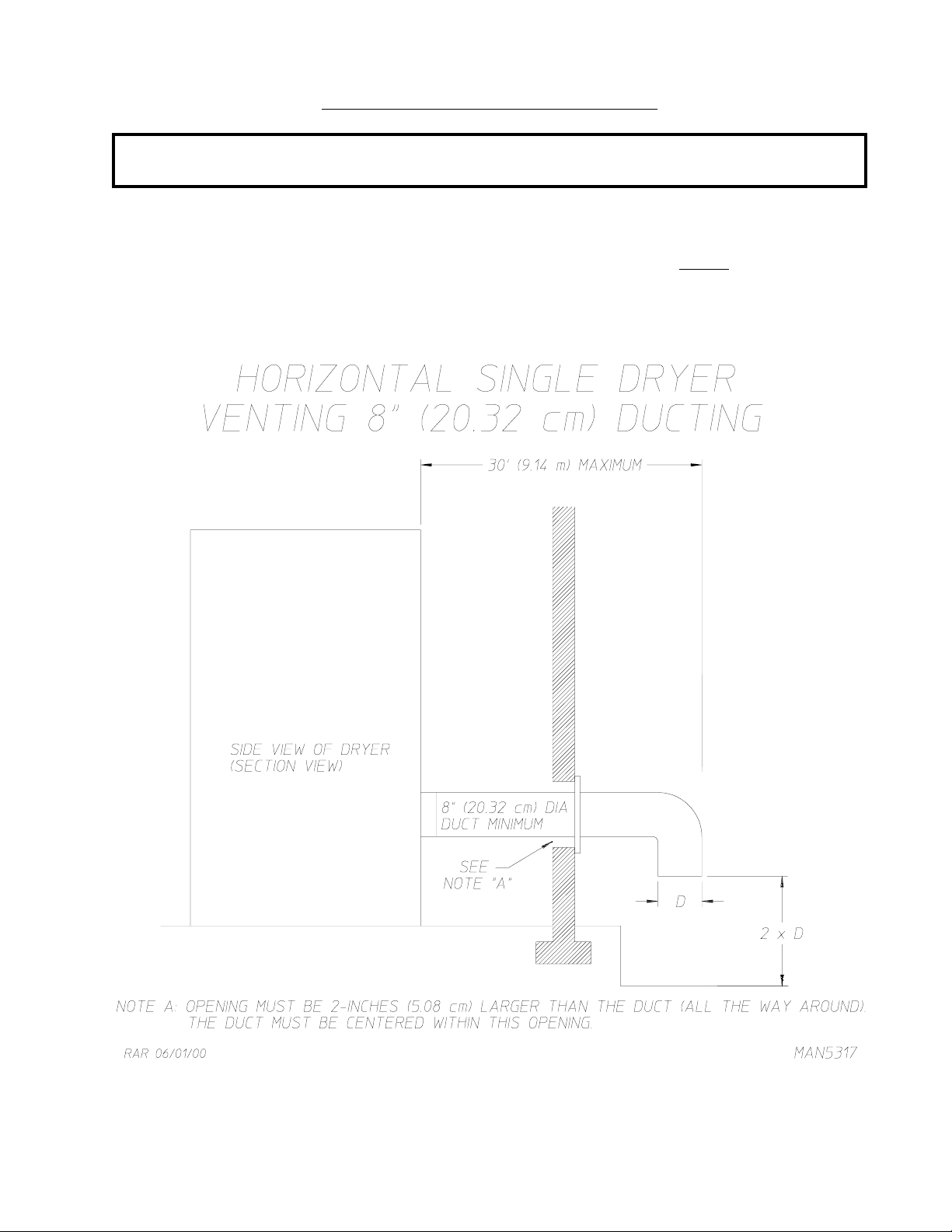
IMPORTANT: For exhaust duct runs over 30 feet (9.14 meters) a minimum size of 10-inches (25.4
cm) must be used.
HORIZONTAL VENTING
When horizontal single 8-inch (20.32 cm) venting is used, the ductwork to the outlet cannot exceed 30 feet (9.14
meters), refer to Illus. A below. This calculation of 30 feet (9.14 meters) compensates or allows for the use of
a maximum of only one (1) elbow .
Illus. A
13
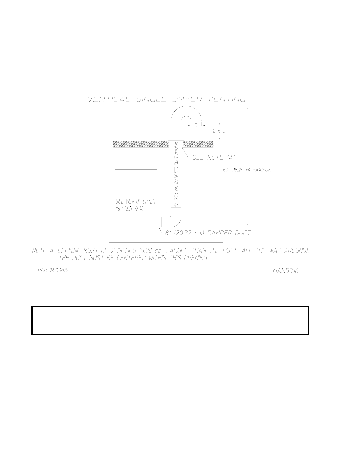
VERTICAL VENTING
When vertical single venting is used, the minimum duct size is 10-inches (25.4 cm), refer to Illus. B below, the
ductwork from the dryer to the outside outlet
This calculation compensates for the use of a maximum of three (3) elbows including the two (2) elbows
creating the 180° (turned downward) outside outlet.
cannot exceed 60 feet (18.29 meters), refer to Illus. B below.
Illus. B
If the length of the duct run or quantity of elbows used exceeds the above noted specifications, the cross section
area of the ductwork must be increased in proportion to the number of elbows or duct run added.
IMPORTANT: For extended ductwork runs, the cross section area of the duct can only be increased
to an extent. For extended ductwork runs, a professional heating, venting, and air
conditioning (HV AC) firm should be consulted for proper venting information.
14
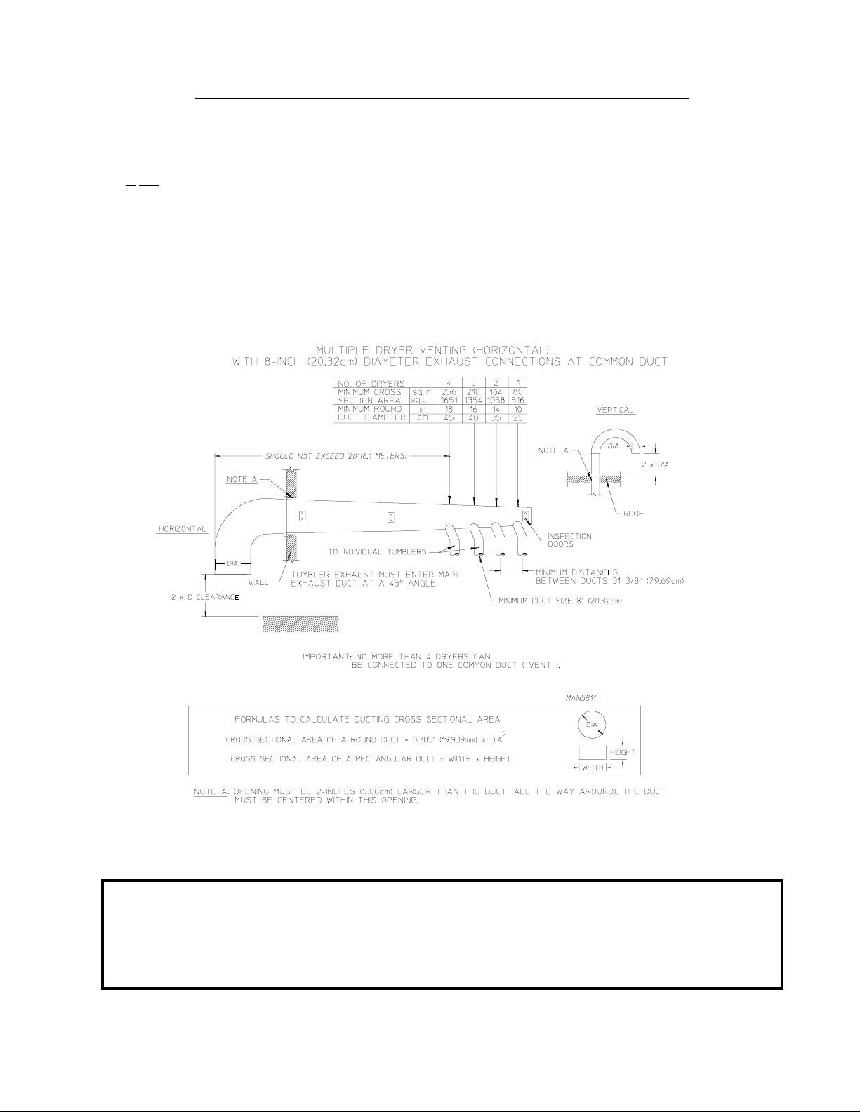
MULTIPLE DR YER (COMMON) VENTING
HORIZONTAL VENTING
If it is not feasible to provide separate exhaust ducts for each dryer , ducts for individual dryers may be channeled
into a common main duct. Each dryer is provided with a back draft damper. The individual ducts should enter
the bottom or side of the main duct at an angle not more than 45° in the direction of the airflow . No more than
four (4) dryers should be connected to one (1) main common duct run.
The main common duct may be any shape so long as the minimum cross-sectional area is provided. The main
duct should be tapered with the diameter increasing before each individual 8-inch (20.32 cm) duct is added
(refer to Illus. C and Illus. D).
Illus. C
Horizontal venting must not exceed 20 feet (6.1 meters), this calculation compensates for the use of a maximum
of only one (1) elbow , which is the outside outlet protection.
NOTE: Distance between dryer single ducts being connected to the main common duct must be a
minimum of 31-3/8” (79.69 cm) dryer width.
Ductwork should be laid out in such a manner where allowances are made at rear area of the
dryer for removal of rear service panels or guards.
Illus. C shows the minimum cross section area for horizontal multiple dryer venting. These figures must be
increased in proportion if the main duct run from the last dryer to where it exhausts has numerous elbows or is
unusually long.
15
IMPORTANT: For extended ductwork runs, the cross section area of the duct can only be increased
to an extent. For extended ductwork runs, a professional heating, venting, and air
conditioning (HV AC) firm should be consulted for proper venting information.
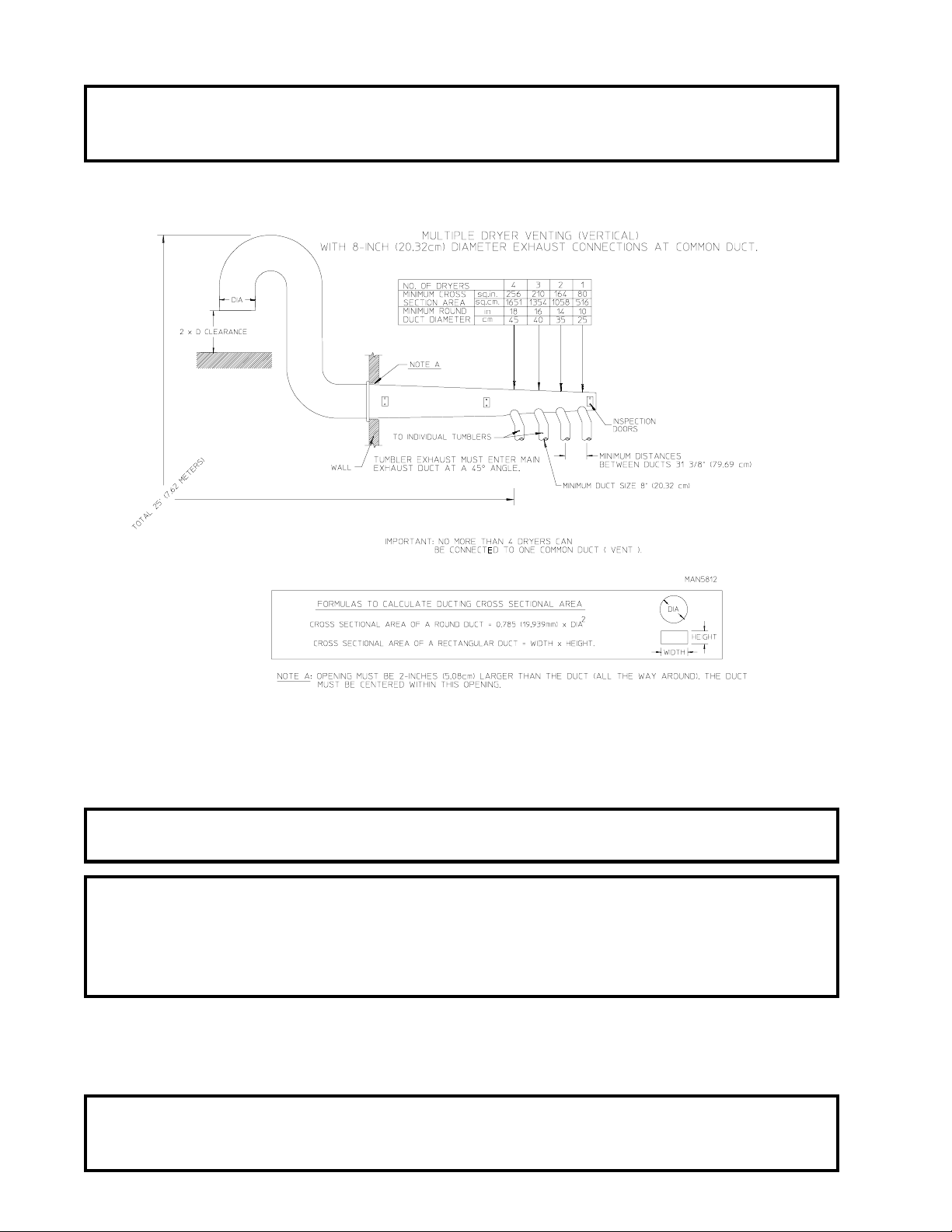
VERTICAL VENTING
Illus. D
The maximum length of venting from the last dryer to where it exhausts...
Vertical venting must not exceed 25 feet (7.62 meters), this calculation compensates for the use of a maximum
of three (3) elbows including the two (2) elbows creating the 180º (turned downward) outside outlet protection.
IMPORTANT: No more than four (4) dryers maximum should be connected to one (1) main
common duct with a vertical run.
NOTE: Distance between dryer single ducts being connected to the main common duct must be a
minimum of 31-3/8” (79.69 cm) dryer width.
Ductwork should be laid out in such a manner where allowances are made at rear area of the
dryer for removal of rear service panels or guards.
Illus. D shows the minimum cross section area for vertical multiple dryer venting. These figures must be
increased in proportion if the main duct run from the last dryer to where it exhausts has numerous elbows or is
unusually long.
IMPORTANT: For extended ductwork runs, the cross section area of the duct can only be increased
to an extent. For extended ductwork runs, a professional heating, venting, and air
conditioning (HV AC) firm should be consulted for proper venting information.
16
 Loading...