

AD-235 Parts Manual
24 VAC Phase 5
1992 thru 2000
American Dryer Corporation
88 Currant Road
Fall River, MA 02720-4781
Telephone: (508) 678-9000 / Fax: (508) 678-9447
E-mail: techsupport@amdry.com
www.amdry.com
ADC Part No. 450133-7

Retain This Manual In A Safe Place For Future Reference
American Dryer Corporation products embody advanced concepts in engineering, design, and safety. If this product is
properly maintained, it will provide many years of safe, efficient, and trouble-free operation.
ONLY qualified technicians should service this equipment.
OBSERVE ALL SAFETY PRECAUTIONS displayed on the equipment or specified in the installation/operator's manual
included with the dryer.
The following “FOR YOUR SAFETY” caution must be posted near the dryer in a prominent location.
FOR YOUR SAFETY
Do not store or use gasoline or
other flammable vapors or liquids
in the vicinity of this or any other
appliance.
We have tried to make this manual as complete as possible and hope you will find it useful. ADC reserves the right to make
changes from time to time, without notice or obligation, in prices, specifications, colors, and material, and to change or
discontinue models.
POUR VOTRE SÉCURITÉ
Ne pas entreposer ni utiliser d’essence
ni d’autres vapeurs ou liquides
inflammables dans le voisinage de cet
appareil ou de yout autre appareil.
Important
For your convenience, log the following information:
DATE OF PURCHAS E MODEL NO.
DIS TRI BUTORS NAME
Serial Number(s)
AD-235
Replacement parts can be obtained from your distributor or the ADC factory. When ordering replacement parts from the
factory, you can FAX your order to ADC at (508) 678-9447 or telephone your orders directly to the ADC Parts Department
at (508) 678-9000. Please specify the dryer model number and serial number in addition to the description and part
number, so that your order is processed accurately and promptly.
The illustrations on the following pages may not depict your particular dryer exactly. The illustrations are a composite
from the various dryer models. Be sure to check descriptions of the parts thoroughly before ordering.
“IMPORTANT NOTE TO PURCHASER”
Information must be obtained from your local gas supplier on the instructions
to be followed if the user smells gas. These instructions must be posted in a
prominent location near the dryer.

Table of Contents
Control Door Assembly .......................................................................................................................... 2
Lower Service Door Assembly ............................................................................................................... 3
Coin Microprocessor Control Panel/Box Assemblies
For models mfd. as of December, 1996 ............................................................... 4, 5
Coin Microprocessor Control Panel/Box Assemblies
For models mfd. prior to December, 1996 ..................................................................................... 6, 7
OPL Microprocessor Control Panel/Box Assemblies
For models mfd. as of December, 1996......................................................................................... 8, 9
OPL Microprocessor Control Panel/Box Assemblies
For models mfd. prior to December, 1996 ................................................................................. 10, 11
Front Panel Assembly ........................................................................................................................... 12
Main Door Switch Assembly................................................................................................................. 13
Main Door Assembly ............................................................................................................................ 14
Lint Drawer Assembly .......................................................................................................................... 15
Basket (Tumbler)/Support Assemblies ............................................................................................. 16, 17
Idler Bearing Assembly ................................................................................................................... 18, 19
Tumbler Bearing Assembly .............................................................................................................. 20, 21
Totally Enclosed, Fan-Cooled Motor Mount Assembly.................................................................... 22, 23
Sensor Bracket Assembly ..................................................................................................................... 24
Sail Switch Assembly ............................................................................................................................ 25
Direct Spark Ignition (DSI) Gas Valve/Burner Assembly .................................................................. 26, 27
Gas Burner Chamber Assembly ............................................................................................................ 28
Gas Piping Assembly ............................................................................................................................ 29
3-Phase (3ø) Motor, Electrical Relay Panel Assembly
For models mfd. as of December, 1996........................................................................................... 30
3-Phase (3ø) Motor, Electrical Relay Panel Assembly
For models mfd. prior to December, 1996 ....................................................................................... 31
Exhaust Ducting Assembly .................................................................................................................... 32
Back Guard Assembly .......................................................................................................................... 33
Microprocessor Coin Acceptor Listing .................................................................................................. 34
Additional Parts Available ..................................................................................................................... 35
2
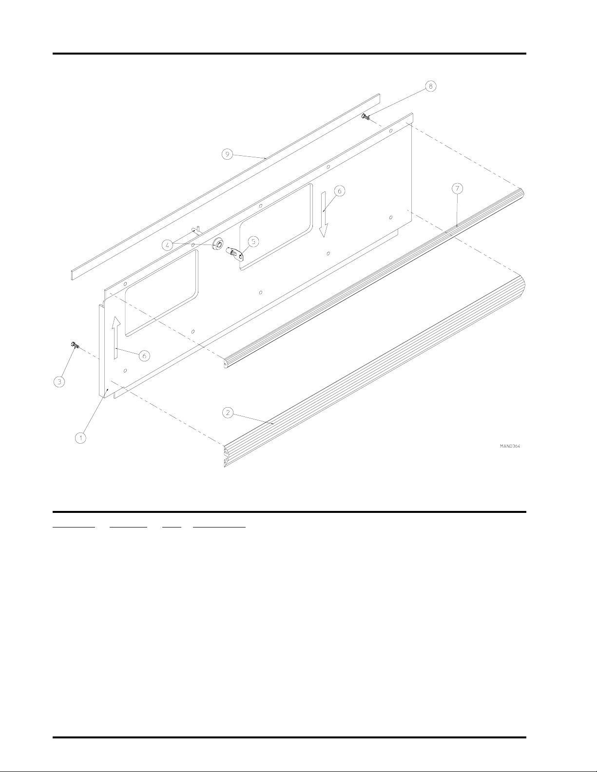
Control Door Assembly
Illus. No. Part No. Qty. Description
1* 880249 1 Control Door Assembly Complete without Lock
(includes illus. nos. 1 through 3 and 7 through 9)
2 180313 1 Lower Black Trim Strip (28-3/8” length)
3 150201 5 #10-32 x 1/4” Phillips Round Head Machine Screw
4 160040 1 ACE® Lock Assembly without Key
5 160140 1 ACE® Key (key no. XX4451) ONLY
6 112077 2 “Arrow” Label
7 180305 1 Upper Black Trim Strip (28-3/8” length)
8 150201 5 #10-32 x 1/4” Phillips Round Head Machine Screw
9 117604 3 Neoprene Sponge Tape (sold by the foot)
For models mfd. as of August 6, 1998
117600 3 Noise Suppressor Tape (sold by the foot)
For models mfd. prior to August 6, 1998
* Specify color when ordering.
American Dryer Corporation 88 Currant Road / Fall River, MA 02720-4781
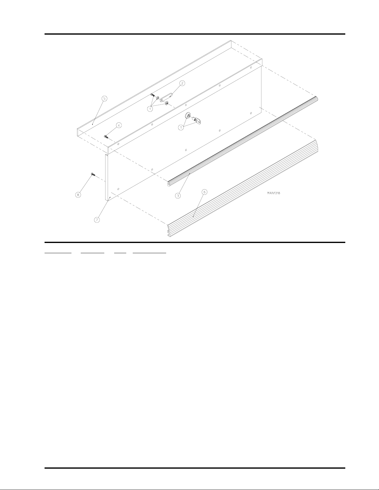
Lower Service Door Assembly
3
Illus. No. Part No. Qty. Description
1* 160038 1 ACE® Lock Assembly without Key
(for models mfd. as of July 20, 1992)
160001 1 AD-100 Lock Assembly Only with Key
(for models mfd. prior to July 3, 1992)
160140 - ACE® Key (key no. XX4451) ONLY
(for models mfd. as of July 20, 1992)
160103 1 AD-100 Key ONLY
(for models mfd. prior to July 3,1992)
2* 160034 1 1-3/8” Lock Cam ONLY
(for models mfd. as of July 20, 1992)
160016 1 1-1/4” Lock Cam ONLY
(for models mfd. prior to July 3, 1992)
3 180305 1 Upper Black Trim Strip (28-3/8” length)
4 150201 5 #10-32 x 1/4” Phillips Round Head Machine Screw
5 117604 3 Neoprene Sponge Tape (sold by the foot)
For models mfd. as of August 6, 1998
117600 3 Noise Suppressor Tape (sold by the foot)
For models mfd. prior to August 6, 1998
6 180313 1 Lower Black Trim Strip (28-3/8” length)
7 880260** 1 Lower Service Door Assembly Complete without Lock
(includes illus. nos. 3 through 8)
8 150201 5 #10-32 x 1/4” Phillips Round Head Machine Screw
* Parts must be purchased separately.
** Specify color when ordering.
Telephone: (508) 678-9000 Fax: (508) 678-9447
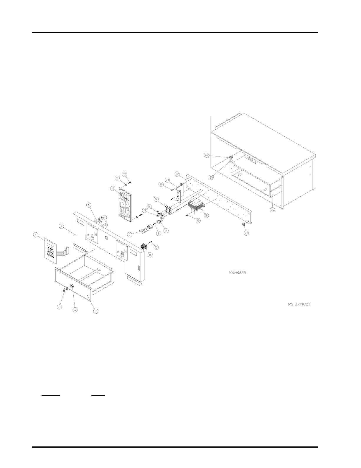
4
Coin Microprocessor Control Panel/Box Assemblies
For models mfd. as of December, 1996
NOTE:DUPLICATE ALL COMPONENTS FOR RIGHT HAND SIDE
CONTROL BOX.
OF
American Dryer Corporation 88 Currant Road / Fall River, MA 02720-4781

Coin Microprocessor Control Panel/Box Assemblies
For models mfd. as of December, 1996
Illus. No. Part No. Qty. Description
1 112526 1 Coin Keyboard Label Assembly
2 824137 1 Phase 5 Control Panel Assembly
(includes illus. nos. 1, 2, and 10 thru 12)
850442 1 Phase 5 Control Panel ONLY
3 802021 1 Standard Coin Box with Face Plate ONLY
802142 1 Standard Coin Box Assembly Complete
(includes illus. nos. 3 through 5)
802144 1 High Security Coin Box with Face Plate ONLY
802143 1 High Security Coin Box Assembly Complete
(includes illus. nos. 3 through 5)
4 160042 1 ACE® Standard Coin Box Lock Only with Key
160043 1 ACE® High Security Coin Box Lock Only with Key
5* 160136 1 ACE® Key ONLY (for standard coin box lock)
160135 1 ACE® Key ONLY (for high security coin box lock)
6 --------- 1 Microprocessor Coin Acceptor
(refer to Microprocessor Coin Acceptor Listing on page 34)
7* * 137056 1 Optical Switch ONLY (GREENWALD)
8* * 137021 3 Microprocessor Socket ONLY
9* * 137023 1 Optical Switch Connector
880772 1 Single Coin Optic Switch Harness
824080 1 Dual Coin Optic Switch Harness
10 137213 1 Phase 5 Coin Microprocessor Controller (computer) ONLY
824998 1 Phase 5 Battery Clip
11 153010 2 #6 Star Washer
12 150005 2 #6-32 x 1/4” Phillips Round Head Machine Screw
13 122706 15 Microprocessor Socket ONLY
14 122641 1 15-Pin Microprocessor Connector ONLY
122800 1 Microprocessor (female) Pin Extraction Tool
15 136057 1 or 2 1/2-Amp (Slo Blo) Fuse
16 150002 1 or 2 #6-32 x 1” Phillips Round Head Machine Screw
17 136008 1 or 2 3-Position Fuse Block
18 826326 1 115v Transformer Assembly
826329 1 208/240v Transformer Assembly
19 150301 2 #8-18 x 7/16 Phillips Head TEK Screw
20 150301 2 #8-18 x 7/16 Phillips Head TEK Screw
21 353258 1 Rear Panel Connector Bracket
22 315028 1 Front Electrical Panel ONLY
23 151001 4 8-32 Pal Nut
24 802140 1 Standard Coin Vault ONLY
802141 1 High Security Coin Vault Only
25** 153018 4 1/4” Flat Washer
26 152014 4 1/4-20 Free Spin Wash Nut
152002*** 4 1/4-20 Hex Nut
5
* Specify key number when ordering.
** For Dual Coin, double the quantity.
** * For use on High Security Coin Vault ONLY.
IMPORTANT: Check label on computer chip to verify correct part number for controller (computer).
Telephone: (508) 678-9000 Fax: (508) 678-9447
6
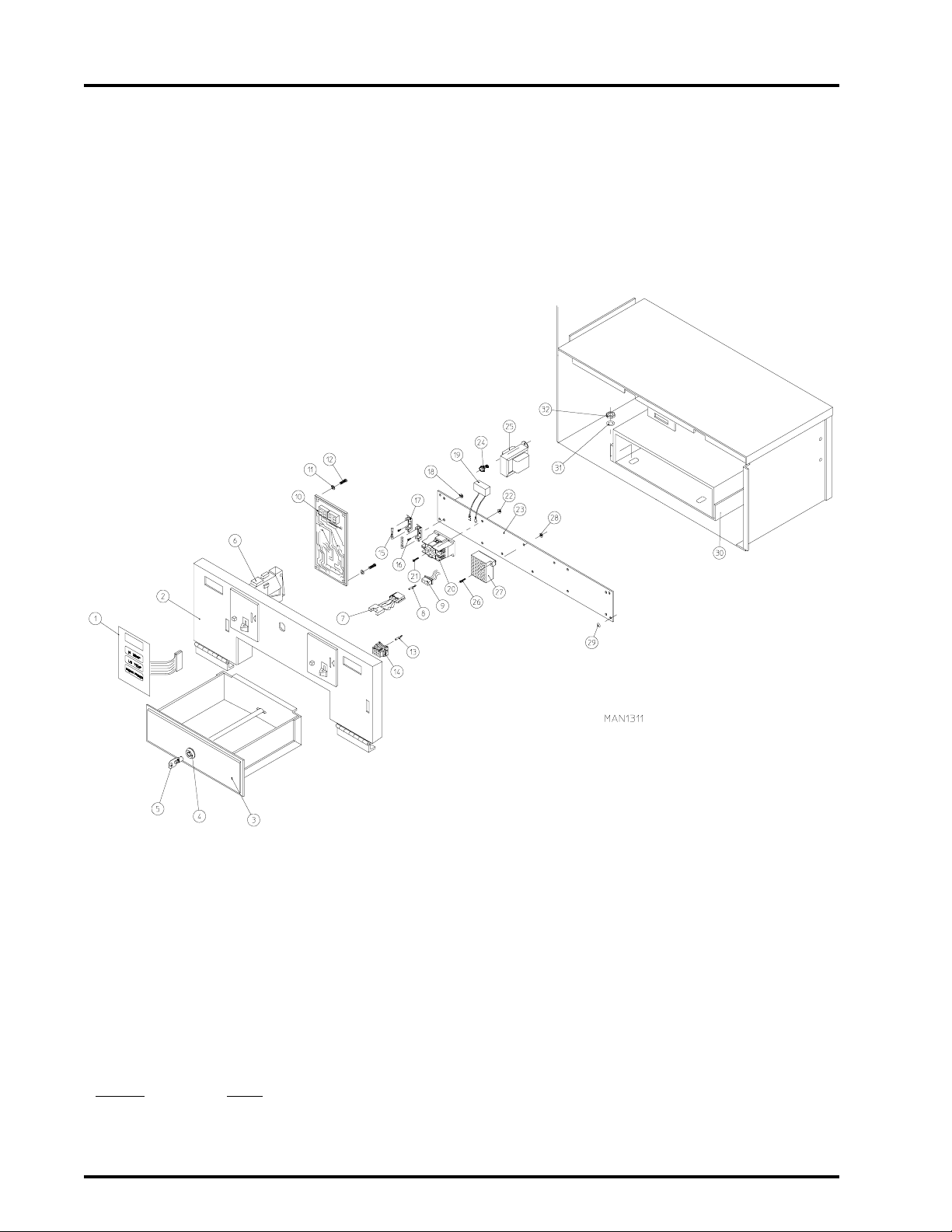
Coin Microprocessor Control Panel/Box Assemblies
For models mfd. prior to December, 1996
NOTE:DUPLICATE ALL COMPONENTS FOR RIGHT HAND SIDE
CONTROL BOX.
OF
American Dryer Corporation 88 Currant Road / Fall River, MA 02720-4781

Coin Microprocessor Control Panel/Box Assemblies
For models mfd. prior to December, 1996
Illus. No. Part No. Qty. Description
1 112526 1 Coin Keyboard Label Assembly
2 824137 1 Phase 5 Control Panel Assembly
(includes illus. nos. 1, 2, and 10 through 12)
850442 1 Phase 5 Control Panel ONLY
3 802021 1 Standard Coin Box with Face Plate ONLY
802142 1 Standard Coin Box Assembly Complete
(includes illus. nos. 5 through 7)
802144 1 High Security Coin Box with Face Plate ONLY
802143 1 High Security Coin Box Assembly Complete
(includes illus. nos. 5 through 7)
4 160042 1 ACE® Standard Coin Box Lock Only with Key
160043 1 ACE® High Security Coin Box Lock Only with Key
5* 160136 1 ACE® Key ONLY (for standard coin box lock)
160135 1 ACE® Key ONLY (for high security coin box lock)
6 --------- 1 Microprocessor Coin Acceptor
(refer to Microprocessor Coin Acceptor Listing on
7* * 137056 1 Optical Switch ONLY (GREENWALD)
8* * 137021 3 Microprocessor Socket ONLY
9* * 137023 1 Optical Switch Connector
880772 1 Single Coin Optic Switch Harness
824080 1 Dual Coin Optic Switch Harness
10 137213 1 Phase 5 Coin Microprocessor Controller (computer) ONLY
824998 1 Phase 5 Battery Clip
11 153010 2 #6 Star Washer
12 150005 2 #6-32 x 1/4” Phillips Round Head Machine Screw
13 122706 15 Microprocessor Socket ONLY
14 122641 1 15-Pin Microprocessor Connector ONLY
122800 1 Microprocessor (female) Pin Extraction Tool
15 136057 1 or 2 1/2-Amp (Slo Blo) Fuse
16 150002 1 or 2 #6-32 x 1” Phillips Round Head Machine Screw
17 136008 1 or 2 3-Position Fuse Block
18 151000 1 or 2 #6-32 Pal Nut
19 824828 1 RC Network with Connectors
20 132451 1 2-Pole Contactor
21 150103 2 #8-32 x 3/4” Phillips Round Head Machine Screw
22 151001 2 #8-32 Pal Nut
23 824435 1 Control Box Panel Assembly Complete - for Gas Models ONLY
(includes illus. nos. 15 through 23, and 26 through 28)
24 150300 2 #10 x 1/2” Hex Washer TEK Screw
25 141403 1 24 VAC Transformer (for 60 Hz models Only)
132023 1 24 VAC Transformer (for 50 Hz models Only)
26 150002 2 #6-32 x 1” Phillips Round Head Machine Screw
27 120715 1 30-Position Terminal Block
28 151000 2 #6-32 Pal Nut
29 151001 6 #8-32 Pal Nut
30 802140 1 Standard Coin Vault ONLY
802141 1 High Security Coin Vault ONLY
31*** 153018 4 1/4” Flat Washer
32 152014 4 1/4-20 Free Spin Wash Nut
152002*** 4 1/4-20 Hex Nut
7
page 34)
* Specify key number when ordering.
** For Dual Coin, double the quantity.
** * For use on High Security Coin Vault ONLY.
IMPORTANT: Check label on computer chip to verify correct part number for controller (computer).
Telephone: (508) 678-9000 Fax: (508) 678-9447
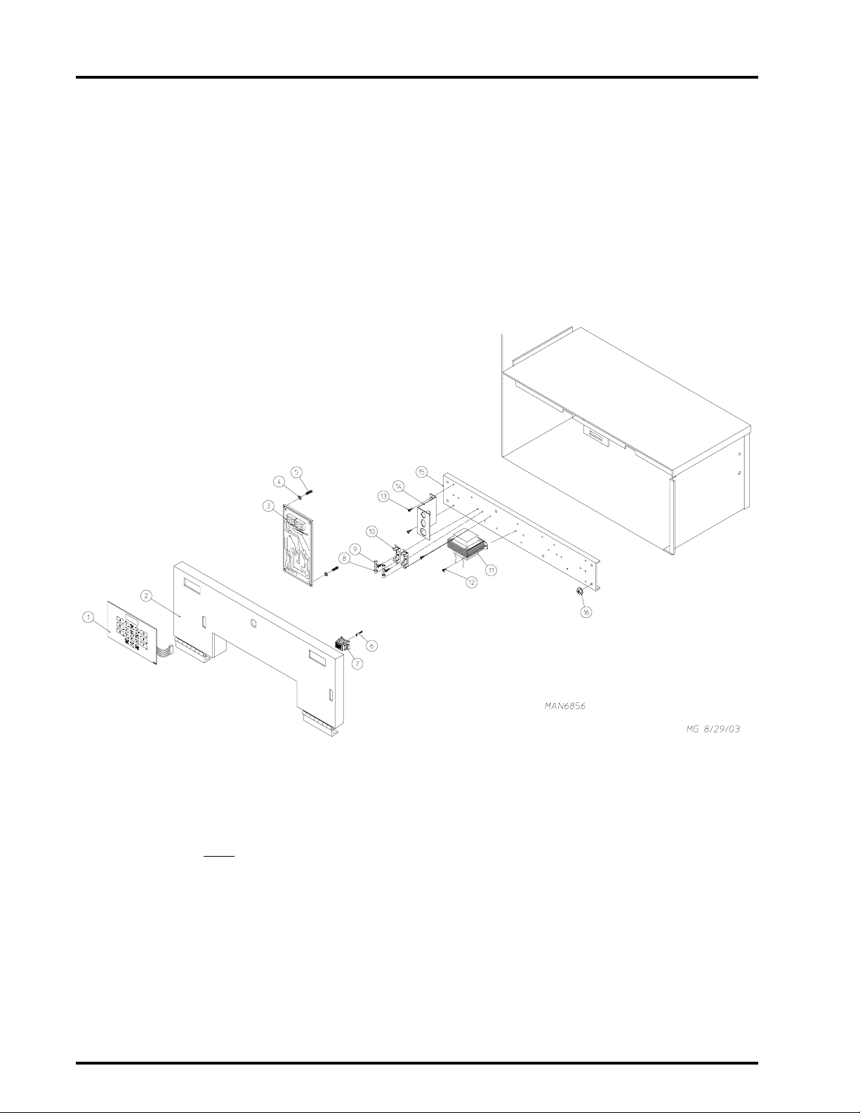
8
OPL Microprocessor Control Panel / Box Assemblies
For models mfd. as of December, 1996
NOTE: Duplicate ALL components for Right Hand Side of Control Box.
American Dryer Corporation 88 Currant Road / Fall River, MA 02720-4781

OPL Microprocessor Control Panel / Box Assemblies
For models mfd. as of December, 1996
Illus. No. Part No. Qty. Description
1 112535 1 OPL English Keyboard Label Assembly
112276 1 OPL Stick-on Labels
(English Only) ... Not Illustrated
112275 1 OPL Stick-on Labels
(Spanish, Italian, and Hebrew) ... Not Illustrated
112277 1 3 Language OPL Stick-on Labels
(English, Spanish, and Hebrew) ... Not Illustrated
112278 1 5 Language OPL Stick-on Labels
(Italian, Dutch, French, German, and Chinese) ... Not Illustrated
2 850470 1 OPL Control Panel ONLY
880844 1 Phase 5 OPL Microprocessor Control Panel Assembly
(includes illus. nos. 1 through 5)
3 137222 1 Phase 5 OPL Microprocessor Controller (computer) ONLY
824998 1 Phase 5 Battery Clip
4 153010 2 #6 Star Washer
5 150005 2 #6-32 x 1/4” Phillips Round Head Machine Screw
6 122706 15 Microprocessor Socket ONLY
7 122641 1 15-Pin Microprocessor Connector ONLY
122800 1 Microprocessor (female) Pin Extraction Tool
8 136057 1 or 2 1/2-Amp (Slo Blo) Fuse
9 150002 1 or 2 #6-32 x 1” Phillips Round Head Machine Screw
10 136008 1 or 2 3-Position Fuse Block
11 826329 1 Transformer Assembly
12 150301 2 #8-18 x 7/16” Phillips Head TEK Screw
13 150301 2 #8-18 x 7/16” Phillips Head TEK Screw
14 353258 1 Rear Panel Connector Bracket
15 315028 1 Front Electrical Panel ONLY
16 151001 6 #8-32 Pal Nut
9
IMPORTANT: Check label on computer chip to verify correct part number for controller (computer).
Telephone: (508) 678-9000 Fax: (508) 678-9447
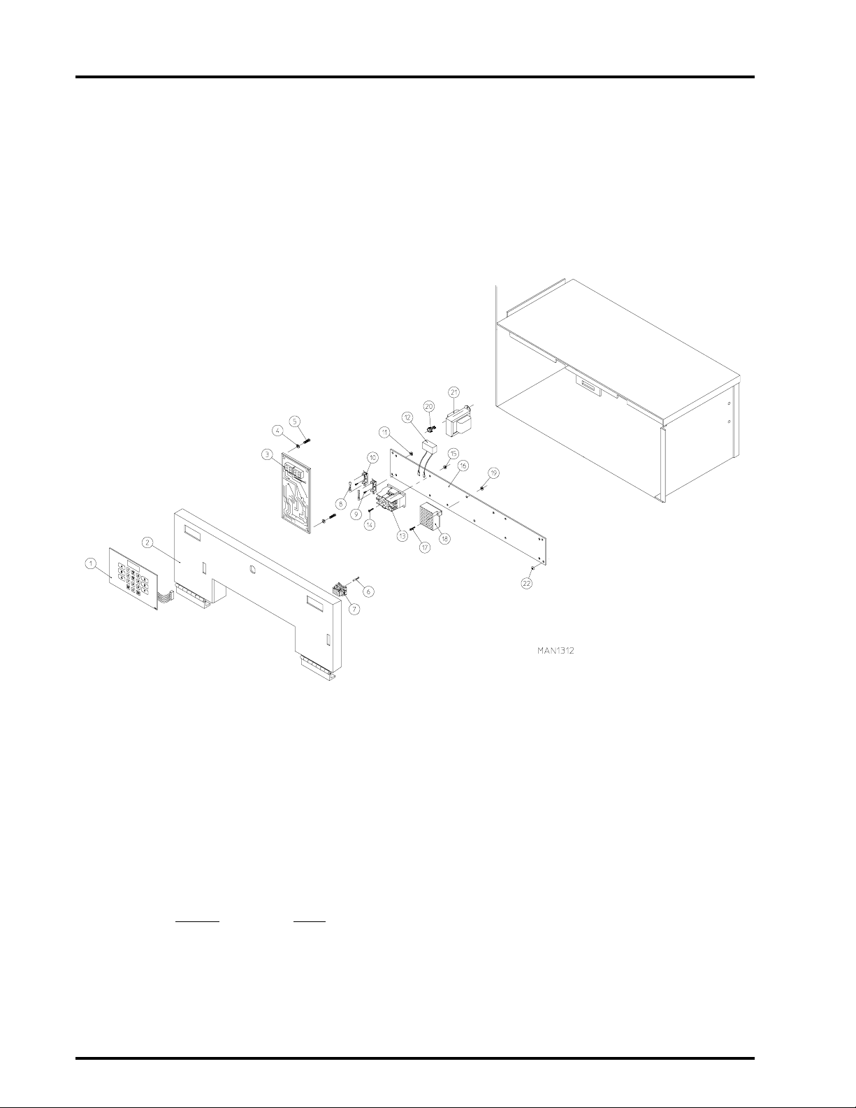
10
OPL Microprocessor Control Panel / Box Assemblies
For models mfd. prior to December, 1996
NOTE:DUPLICATE ALL COMPONENTS FOR RIGHT HAND SIDE
CONTROL BOX.
OF
American Dryer Corporation 88 Currant Road / Fall River, MA 02720-4781

OPL Microprocessor Control Panel / Box Assemblies
For models mfd. prior to December, 1996
Illus. No. Part No. Qty. Description
1 112535 1 OPL English Keyboard Label Assembly
112276 1 OPL Stick-on Labels
(English Only) ... Not Illustrated
112275 1 OPL Stick-on Labels
(Spanish, Italian, and Hebrew) ... Not Illustrated
112277 1 3 Language OPL Stick-on Labels
(English, Spanish, and Hebrew) ... Not Illustrated
112278 1 5 Language OPL Stick-on Labels
(Italian, Dutch, French, German, and Chinese) ... Not Illustrated
2 850470 1 OPL Control Panel Only
880844 1 Phase 5 OPL Microprocessor Control Panel Assembly
(includes illus. nos. 1 through 5)
3 137222 1 Phase 5 OPL Microprocessor Controller (computer) ONLY
824998 1 Phase 5 Battery Clip
4 153010 2 #6 Star Washer
5 150005 2 #6-32 x 1/4” Phillips Round Head Machine Screw
6 122706 15 Microprocessor Socket ONLY
7 122641 1 15-Pin Microprocessor Connector ONLY
122800 1 Microprocessor (female) Pin Extraction Tool
8 136057 1 or 2 1/2-Amp (Slo Blo) Fuse
9 150002 1 or 2 #6-32 x 1” Phillips Round Head Machine Screw
10 136008 1 or 2 3-Position Fuse Block
11 151000 1 or 2 #6-32 Pal Nut
12 824828 1 RC Network with Connectors
13 132451 1 2-Pole Contactor
14 150103 2 #8-32 x 3/4” Phillips Round Head Machine Screw
15 151001 6 #8-32 Pal Nut
16 824435 1 Control Box Panel Assembly Complete
(includes illus. nos. 8 through 19)
For Gas Models ONLY
17 150002 2 #6-32 x 1” Phillips Round Head Machine Screw
18 120715 1 30-Position Terminal Block
19 151000 2 #6-32 Pal Nut
20 150300 2 #10 X 1/2” Hex Washer TEK Screw
21 141403 1 24 VAC Transformer (for 60 Hz models Only)
132023 1 24 VAC Transformer (for 50 Hz models Only)
22 151001 6 #8-32 Pal Nut
11
IMPORTANT: Check label on computer chip to verify correct part number for controller (computer).
Telephone: (508) 678-9000 Fax: (508) 678-9447

12
UPPER FRONT PANEL ASSEMBLY
Front Panel Assembly
NOTE:DUPLICATE ALL COMPONENTS EXCEPT LOGO FOR
FRONT PANEL ASSEMBLY.
LOWER
Illus. No. Part No. Qty. Description
1 800692* 1 Right Hand Insulated Front Panel Assembly
(includes illus. nos. 1, 2, 3, and 6)
2 154215 2 1/8” Pop Rivet
3 170330 1 Friction Door Latch
4 881053 1 ADC Logo with Mounting Tape
5 150309 8 #10-16 x 1/2” Hex Head TEK Crimptite Screw
6 121405 1 Rubber Grommet
* Specify color when ordering.
American Dryer Corporation 88 Currant Road / Fall River, MA 02720-4781

Main Door Switch Assembly
13
Illus. No. Part No. Qty. Description
1 152012 2 #6-32 Hex Nut
2 153008 2 #6 Lock Washer
3 137005 1 Single Pole Door Switch
4 121028 2 Insulated Female Terminal
5 154281 2 3/8” Nylon Spacer
6 800448 1 12-1/2” Stainless Steel Main Door Hinge
(includes illus. nos. 6 and 7)
7 153565 2 #6 Stud
8 881246 1 Main Door Switch Housing ONLY
9 150201 2 #10-32 x 1/4” Phillips Pan Head Screw
10 121405 1 Rubber Grommet
Telephone: (508) 678-9000 Fax: (508) 678-9447

14
Main Door Assembly
Illus. No. Part No. Qty. Description
1 881422 1 Black Plastic Main Door Assembly Complete with Mechanical Fasteners
(includes illus. nos. 1 and 5 through 9)
2 800448 4 12-1/2” Stainless Steel Main Door Hinge Assembly
3 150410 4 #10-24 x 3/8” Phillips Pan Head Taptite Screw
4 152014 1 1/4-20 Free Spin Wash Nut
5 102349 1 Main Door Gasket
6 102212 1 20-7/16” Door Glass with (4) Holes
170730 1 Main Door Glass Adhesive (10.3 oz. cartridge)
7 150448 4 1/2” Stainless Steel Flat Head Allen Screw
8 170319 4 Door Glass (Nylon) Spacer
9 150431 1 Main Door Latch Screw
(#10 x 7/16” Dome Hex Head)
American Dryer Corporation 88 Currant Road / Fall River, MA 02720-4781

Lint Drawer Assembly
15
UPPER LINT DRAWER ASSEMBLY
NOTE:DUPLICATE ALL COMPONENTS EXCEPT PROGRAM
LOCATION LABEL FOR LOWER LINT DRAWER
ASSEMBLY.
Illus. No. Part No. Qty. Description
1 850667* 1 Lint Drawer Assembly
2 112040 1 Lint Label
3 112533 1 “Phase 5 Coin Program Location” Label
(for use on Coin Models Only)
112534 1 “Phase 5 OPL Program Location” Label
(for use on Non-Coin Models Only)
* Specify color when ordering
Telephone: (508) 678-9000 Fax: (508) 678-9447

16
Basket (Tumbler)/Support Assemblies
American Dryer Corporation 88 Currant Road / Fall River, MA 02720-4781

Basket (Tumbler)/Support Assemblies
Illus. No. Part No. Qty. Description
1 800831 1 Basket (Tumbler) and Support Assembly Complete with Felt Collar
(includes illus. nos. 1 through 11)
800721* 1 Basket (Tumbler) ONLY
(includes illus. nos. 1, 2, and 6)
800891 1 Stainless Steel Basket (Tumbler) and Support Assembly Complete
with Felt Collar
(includes illus. nos. 1 through 11)
800841* 1 Stainless Steel Basket (Tumbler) ONLY
(includes illus. nos. 1, 2, and 6)
2 301315 2 Short Basket (Tumbler) Rib ONLY
301316 1 Tall Basket (Tumbler) Rib ONLY
301414 2 Stainless Steel Short Basket (Tumbler) Rib ONLY
301415 1 Stainless Steel Tall Basket (Tumbler) Rib ONLY
3 150518 1 5/16-18 x 3/8” Socket Button Head Screw
4 100902 3 5/16-18 x 31” Tie Rod
5 153001 3 5/16” Flat Washer
6 154210 30 5/32” x 3/16” Pop Rivet
7 800617 1 Basket (Tumbler) Support ONLY
8 152004 3 5/16-18 Hex Nut
9 153002 3 5/16” Lock Washer
10 153001 3 5/16” Flat Washer
11 116003 1 Felt Collar ONLY
115092 1 Inner (Front) Felt Collar ONLY (Not Illustrated)
401010 1 #847 Adhesive for Felt Collar (5 oz. tube)
17
* Felt collars are not included and must be ordered separately.
Telephone: (508) 678-9000 Fax: (508) 678-9447

18
Idler Bearing Assembly
American Dryer Corporation 88 Currant Road / Fall River, MA 02720-4781

Idler Bearing Assembly
Illus. No. Part No. Qty. Description
1 100113 1 4L-400 V- Belt (idler to motor)
For 60 Hz models ONLY
100115 1 4L-410 V-Belt (idler to motor )
For 50 Hz models ONLY
2 101129 1 9” x 2-1/2” Pulley with 3/16” Key
3 154301 2 5/16-18 x 5/16” Allen Set Screw
4 100100 1 5L-660 V-Belt (idler to basket/tumbler)
5 100705 1 3/16” x 3/16” x 1-3/8” Key
6 301850 1 5/8” x 3/4” Idler Shaft
7 150529 3 1/4-20 x 2-1/4” Carriage Bolt
8 100214 2 5/8” Flange Bearing
9 153007 3 1/4” Lock Washer
10 152002 3 1/4-20 Hex Nut
11 150617 2 3/8-16 x 1” Hex Head Machine Bolt
12 153005 2 3/8” Lock Washer
13 153004 2 3/8” Flat Washer
14 152020 1 5/16-18 Standard Square Nut
15 152004 1 5/16-18 Hex Nut
16 801010 1 Idler Bearing Assembly Complete
(includes illus. nos. 6 through 17)
100406 1 Idler Bearing Mount ONLY
17 150509 1 5/16-18 x 3” Hex Head Machine Bolt
18 --------- - DSI Module Mounting Bracket
(refer to DSI Gas Valve/Burner Assembly on
19
page 26 and page 27)
Telephone: (508) 678-9000 Fax: (508) 678-9447

20
Tumbler Bearing Assembly
American Dryer Corporation 88 Currant Road / Fall River, MA 02720-4781

Tumbler Bearing Assembly
Illus. No. Part No. Qty. Description
1 880203 1 1-3/8” Flange Bearing with Nylock Set Screw
2 153005 4 3/8” Lock Washer
3 152005 4 3/8-16 Hex Nut
4 150508 2 3/8-16 x 3/4” Hex Head Machine Bolt
5 153005 2 3/8” Lock Washer
6 152005 2 3/8-16 Hex Nut
7 150600 2 3/8-16 x 1-1/2” Hex Head Machine Bolt
8 153004 2 3/8” Flat Washer
9 153005 2 3/8” Lock Washer
10 152005 2 3/8-16 Hex Nut
11 150501 4 5/16-18 x 3/4” Hex Head Machine Bolt
12 153002 4 5/16” Lock Washer
13 153001 4 5/16” Flat Washer
14 150621 2 5/16-18 x 1-1/2” Hex Head Machine Bolt
15 152004 2 5/16-18 Hex Nut
16 801101 1 1-3/8” Bearing Box Assembly Complete
(includes illus. nos. 4 through 20)
For models mfd. without rotational sensor
801103 1 1-3/8” Bearing Box and Support ONLY
(includes illus. nos. 9, 10, 13, 14, and 15)
801105 1 1-3/8” Bearing Box ONLY
17 801104 1 Pillow Block Bearing Support ONLY
18 880779 1 1-3/8” Pillow Block Bearing Assembly with Magnet
(for models mfd. without rotational sensor)
100202 1 1-3/8” Pillow Block Bearing with Nylock Set Screw
19 152004 2 5/16-18 Hex Nut
20 150610 2 5/16-18 x 1-1/2” Allen Set Screw
21 101100 1 18” Cast Pulley
22 154301 2 5/16-18 x 5/16” Allen Set Screw
23 100713 1 1/4” x 1/4” x 7/8” Key
24 100100 1 5L-660 V-Belt (basket/tumbler to idler)
25 824807 1 Rotational Sensor Assembly
21
Telephone: (508) 678-9000 Fax: (508) 678-9447

22
Totally Enclosed, Fan-Cooled Motor Mount Assembly
American Dryer Corporation 88 Currant Road / Fall River, MA 02720-4781

Totally Enclosed, Fan-Cooled Motor Mount Assembly
Illus. No. Part No. Qty. Description
1 100604 1 12-1/2” Impellor with 1/2” Bore
2 152006 2 1/2-20 Left Hand Jam Nut
3 153050 2 1/2” S.A.E. Flat Washer
4 100702 1 1/8” x 1/8” x 1-1/2” Key
5 153050 * 1/2” S.A.E. Flat Washer
6 117600 4 Noise Suppressor Tape (sold by the foot)
7 850019 1 Motor Mount ONLY
803963** 1 1/2 HP 100/120-230v 1ø 50/60 Hz T.E.F.C. Motor Mount Assembly Complete
with Plug Motor
(includes illus. nos. 1 through 7 and 11 through 17)
For models mfd. as of August 28, 1992
880848** 1 1/2 HP 208/230/380/460v 60Hz 3ø T.E.F.C. Motor Mount Assembly Complete
(includes illus. nos. 1 through 7, 11, 13 through 17, 22, and 23)
803902** 1 1/2 HP 208/230/380/460v 3ø 50 Hz T.E.F.C. Motor Mount Assembly Complete
(includes illus. nos. 1 through 7, 11, 13 through 17, 22, and 23)
803887 1 1/2 HP 240v 1ø 50 Hz T.E.F.C. Motor Mount Assembly Complete
without Plug Motor
(includes illus. nos. 1 through 7, 11, 13, through 17, 22, and 23)
For models mfd. prior to August 28, 1992
8 150501 4 5/16-18 x 3/4” Hex Head Machine Bolt
9 153002 4 5/16” Lock Washer
10 153001 4 5/16” Flat Washer
11 154000 4 5/16-18 Tinnerman Nut
12 100065** 1 1/2 HP 100-230v 1ø 50/60 Hz T.E.F.C. Motor with Plug
100066 1 1/2 HP 240v 1ø 50 Hz T.E.F.C. Motor with Plug
(for models mfd. as of August 28, 1992)
13 150501 4 5/16-18 x 3/4” Hex Head Machine Bolt
14 153002 4 5/16” Lock Washer
15 153001 4 5/16” Flat Washer
16 153001 * 5/16” Flat Washer
17 101131 1 1/2” x 2-1/4” Motor Pulley
(for use on 1ø - 60 Hz models Only)
101133 1 5/8” x 2-1/4” Motor Pulley
(for use on 3ø - 60 Hz models Only)
101130 1 5/8” x 2-1/2” Motor Pulley
(for use on 1ø/3ø - 60 Hz models Only)
18 100113 1 4L-400 V-Belt (motor to idler)
For use on 60 Hz models ONLY
4L-410 V-Belt (motor to idler)
For use on 50 Hz models ONLY
19 122701 8 Socket Terminal ONLY
20 137030 1 8-Pin Housing ONLY
122801 1 Pin/Socket Extraction Tool
21 837005 1 120 Volt 1ø Motor Harness with Plug
837006 1 230 Volt 1ø Motor Harness with Plug
22 100007 1 1/2 HP 208/230/380/460v 3ø 50/60 Hz T.E.F.C. Motor
100035 1 1/2 HP 240v 1ø 50 Hz T.E.F.C. Motor
(for models mfd. prior to August 28, 1992)
23 120200 1 3/8” x 90º Connector
24 100701 1 3/16” x 3/16” x 1” Key
(for use on 3ø models Only)
23
* As required.
** Specify voltage when ordering.
Telephone: (508) 678-9000 Fax: (508) 678-9447

24
Sensor Bracket Assembly
Illus. No. Part No. Qty. Description
1 880251 1 1/4” Temperature Sensor Probe Assembly
(includes illus. nos. 1 through 4)
2 122605 1 4-Pin Socket Connector ONLY
3 122701 4 Socket Terminal Only
4 154007 2 1/4” Tinnerman Push-on Fastener
5 150000 2 #6-32 x 1/4” Round Head Machine Screw
6 801428 1 Sensor Bracket Assembly Complete
(includes illus. nos. 1 through 9)
305107 1 Temperature Sensor Bracket ONLY
7 130103 1 225º Large Automatic Thermostat
8 153010 2 #6 Star Washer
9 152000 22 #6-32Hex Nut
10 150301 2 #8-18 x 7/16” Phillips Pan Head TEK Screw
11 122604 1 4-Pin Connector ONLY
12 122700 4 Pin Terminal ONLY
-- 122801 1 Pin/Socket Extraction Tool
American Dryer Corporation 88 Currant Road / Fall River, MA 02720-4781

Sail Switch Assembly
25
Illus. No. Part No. Qty. Description
1 150301 2 #8-18 x 7/16" Phillips Pan Head TEK Screw
2 802800 1 Sail Switch Box with Cover and Bracket ONLY
(includes illus. nos. 2, 4, and 5)
3 154004 1 Twin Speed Nut
4 150309 2 10-16 x 1/2” Phillips Round Head Crimptite Screw
5 802709 1 Sail Switch Box Cover and Bracket ONLY
6 122200 1 Sail Switch ONLY
7 150303 2 #4 x 3/4" Pan Head “A” Machine Screw
8 105500 1 Sail Switch Actuator Rod
9 319202 1 Sail Switch Damper (embossed)
10 154002 1 1/8” Push-on Fastener
Telephone: (508) 678-9000 Fax: (508) 678-9447

26
Direct Spark Ignition (DSI) Gas Valve/Burner Assembly
American Dryer Corporation 88 Currant Road / Fall River, MA 02720-4781

Direct Spark Ignition (DSI) Gas Valve/Burner Assembly
Illus. No. Part No. Qty. Description
1 850804 1 DSI Gas Valve/Burner Tube Mounting Plate ONLY
809313* 1 DSI (natural gas) Valve/Burner Assembly Complete less Orifice
(includes illus. nos. 1, 3, 5 through 10 and 12 through 21)
809314* 1 DSI (liquid propane) Gas Valve/Burner Assembly Complete less Orifice
(includes illus. nos. 1, 3, 5 through 10 and 12 through 21)
2 150300 2 #10 x 1/2” Hex Washer TEK Screw
3 141317 1 1/2” Bronze Union Elbow
4 318650 1 Notched Pipe Bracket
5 150301 2 #8-18 x 7/16” Phillips Pan Head TEK Screw
6 128927 1 1/2” 24 VAC Redundant (natural gas) Valve
880960 1 1/2” 24 VAC Gas Valve L.P. (liquid propane)
7 318650 1 Notched Pipe Bracket
8 150301 2 #8-18 x 7/16” Phillips Pan Head TEK Screw
9 141235 1 1/2” Single Port Manifold
10* 140828 1 #20 Burner Orifice (natural gas) ONLY
140811 1 #41 Burner Orifice (liquid propane gas) ONLY
11 153000 1 #8 Steel Burr
12 152001 1 #8-32 Hex Nut
13 141131 1 DSI (Direct Spark Ignition) Up-Shot Burner Tube with Flame Spreader
141130 1 DSI (Direct Spark Ignition) Up-Shot Burner Tube ONLY
141109 1 Flame Spreader ONLY
14 318009 1 Burner Tube Bracket (PSE)
15 150315 2 #6 x 3/8” Phillips Pan Head Machine Screw
16 128917 1 Spark Electrode with High Voltage (HV) Wire
305412 1 DSI Ignitor Gap Feeler Gauge ... Not Illustrated
17 128918 1 Flame Sensor Probe
18 121006 1 #10 Insulated Terminal
19 132607 2 #18 Gauge Red Silicone Wire (sold in feet)
20 121028 1 1/4” x .032 Insulated Terminal
21 880815 1 ADC DSI Module ONLY (50/60 Hz)
22 151000 4 #6-32 Pal Nut
23 801042 1 DSI Stud Plate Assembly ONLY
(for models mfd. as of September 16, 1998)
801013 1 DSI Module Mounting Bracket ONLY
(for models mfd. prior to September 16, 1998)
24 152014 1 1/4-20 Free Spin Wash Nut
25 --------- - Idler Bearing Mount
(refer to Idler Bearing Assembly on
-- 874059** 1 ADG-235 Burner L.P. Conversion Kit with Orifice
page 18 and page 19)
27
* Burner Orifice is not included and must be ordered separately.
** Consult factory for elevations over 2,000 feet.
Telephone: (508) 678-9000 Fax: (508) 678-9447

28
Gas Burner Chamber Assembly
Illus. No. Part No. Qty. Description
1 804025 1 Gas Burner/Electric Oven Chamber Assembly
(includes illus. nos. 1, 2, and 3)
2 318006 1 Flame Viewing Plate
3 150300 2 #10 x 1/2” Hex Washer TEK Screw
4 802502 1 Hi Limit Bracket Assembly
(includes illus. nos. 4 through 8)
319710 1 Hi Limit Bracket ONLY
5 150301 2 #8-18 x 7/16” Phillips Pan Head TEK Screw
6 150001 2 #6-32 x 1/2” Right Hand Machine Screw
7 130103 1 225º Large Automatic Thermostat
8 151000 2 #6-32 Pal Nut
American Dryer Corporation 88 Currant Road / Fall River, MA 02720-4781

Gas Piping Assembly
29
Illus. No. Part No. Qty. Description
1 318702 1 Top Pipe Support Bracket ONLY
2 150300 2 #10 x 1/2” Hex Washer TEK Screw
3 141236 1 Gas Piping Manifold
4 881367 2 Angle Union Shut Off with 1/2” Tail Piece
Telephone: (508) 678-9000 Fax: (508) 678-9447

30
3-Phase (3ø) Motor, Upper Electrical Relay Panel Assembly
For models mfd. as of December, 1996
Illus. No. Part No. Qty. Description
1 150009 4 6-32 x 1 1/2 Phillip Pan Head Machine Screw
2 120701 2 4 Position Power Terminal Block
3 121300 2 Open/Close Bushing
4 353142 2 Power Block Mounting Bracket
5 137015 1 RC Network
6 151000 4 6-32 Pal Nut
7 152001 4 #8-32 Hex Nut
8 153012 4 #8 Internal Star Washer
9 132447 1 3 Pole Contactor
10* 850474 1 Rear Electrical Box ONLY
315062 1 Rear Electric Box Cover (Not Illustrated)
* Lower Electrical Relay Panel is the same as Upper, excluding items 1 through 6
American Dryer Corporation 88 Currant Road / Fall River, MA 02720-4781

3-Phase (3ø) Motor, Electrical Relay Panel Assembly
For models mfd. prior to December, 1996
31
Illus. No. Part No. Qty. Description
1 150300 2 #10 x 1/2” Hex Washer TEK Screw
2 321002 1 Electrical Relay Panel Cover ONLY
3 137015 1 Arc Suppressor (capacitor)
4 132430 1 Impellor Contactor Coil - 24 VAC
(208/230/240v - 50/60 Hz)
132432 1 Impellor Contactor Replacement Coil - 24 VAC
(208/230/240v - 50/60 Hz)
5 150108 4 #8-32 x 1/2” Phillips Pan Head Machine Screw
6 150300 2 #10 x 1/2” Hex Washer TEK Screw
7 151001 4 #8-32 Pal Nut
8 311920 1 3-Phase (3ø) Contactor Mounting Bracket ONLY
9 850909 1 Electrical Relay Panel Assembly
(includes illus. nos. 1, 2, and 9 )
Telephone: (508) 678-9000 Fax: (508) 678-9447

32
Exhaust Ducting Assembly
Illus. No. Part No. Qty. Description
1 880505 1 Wye Branch Damper Assembly
2 143527 1 6” Round x 7” Oval Straight Boot
3 143539 1 15-1/2” x 7” Oval Duct
4 143537 1 7” Oval x 45º Elbow
5 143538 1 6” Round x 7” Oval Straight Boot
6 143536 1 6” Round x 45º Elbow
7 121104 1 Junction Box Only
8 121105 1 Junction Box Cover ONLY
150301 2 #8-18 x 7/16” Phillips Pan Head TEK Screw ... Not Illustrated
9 315025 1 Rear Wiring Box Cover ONLY
150300 2 #10 x 1/2” Hex Washer TEK Screw ... Not Illustrated
10 121104 1 Junction Box
11 121105 1 Junction Box Cover ONLY
150301 2 #8-18 x 7/16” Phillips Head TEK Screw ... Not Illustrated
12 143536 1 6” Round x 45º Elbow
13 315025 1 Rear Wiring Box Cover ONLY
150300 2 #10 x 1/2” Hex Washer TEK Screw ... Not Illustrated
-- 117505 * Aluminum Duct Tape (sold by the foot)
* As required.
American Dryer Corporation 88 Currant Road / Fall River, MA 02720-4781

Back Guard Assembly
33
Illus. No. Part No. Qty. Description
1 311014 2 Upper/Lower Back Guard Assembly
2 150301 16 #8-18 x 7/16” Phillips Pan Head TEK Screw
3 318702 1 Top Pipe Support Bracket ONLY
4 150300 2 #10 x 1/2” Hex Washer TEK Screw
5 103500 4 Adjustable Leveling Leg
Telephone: (508) 678-9000 Fax: (508) 678-9447

34
NOTE: Coin acceptors listed include Optical Switch (ADC Part No. 137056).
Microprocessor Coin Acceptor Listing
SINGLE COIN*
ADC Part No. Nation Description
125100 U.S. and Canada 25¢ Optic Coin Acceptor
125127 Canada $1 Canadian Optic Coin Acceptor
125101 United Kingdom 10 New Pence Optic Coin Acceptor
125114 United Kingdom 20 New Pence Optic Coin Acceptor
125115 United Kingdom 1 Pound Optic Coin Acceptor
125106 France 1 French Franc Optic Coin Acceptor
125120 France 2 French Franc Optic Coin Acceptor
125124 France 5 French Franc Optic Coin Acceptor
125109 Denmark 1 Danish Krone Optic Coin Acceptor
125125 Netherlands 25¢ Guilder Optic Coin Acceptor
125108 Australia 10¢ Australian Optic Coin Acceptor
125107 Australia 20¢ Australian Optic Coin Acceptor
125130 Australia $1 Australian Optic Coin Acceptor
125123 New Zealand 50¢ New Zealand Optic Coin Acceptor
125104 Japan 100 Yen Optic Coin Acceptor
125103 --- .882 Token Optic Coin Acceptor
125121 --- .800 Token Optic Coin Acceptor
125129 --- Muller Token Optic Coin Acceptor
125132 Singapore 50¢ Singapore Optic Coin Acceptor
125133 Hong Kong $1 Hong Kong Optic Coin Acceptor
DUAL COIN*
125116 U.S. and Canada 10¢ / 25¢ Dual Optic Coin Acceptor
125128 Canada 25¢ / $1 Dual Optic Coin Acceptor
125112 United Kingdom 10 / 20 Pence Dual Optic Coin Acceptor
125110 United Kingdom 10 / 50 Pence Dual Optic Coin Acceptor
125111 United Kingdom 20 / 50 Pence Dual Optic Coin Acceptor
125113 United Kingdom 1£ / 20 Pence Dual Optic Coin Acceptor
125122 France 2 / 5 Franc Dual Optic Coin Acceptor
125117 Denmark 1 / 5 Danish Krone Dual Optic Coin Acceptor
125131 Denmark 5 / 10 Danish Krone Dual Optic Coin Acceptor
125126 Netherlands 25¢ / 1 Guilder Dual Optic Coin Acceptor
125118 Singapore 20¢ / 50¢ Singapore Dual Optic Coin Acceptor
125105 Japan 50 / 100 Yen Dual Optic Coin Acceptor
* Consult factory for coin acceptors not listed
American Dryer Corporation 88 Currant Road / Fall River, MA 02720-4781

Additional Parts Available
Part No. Description
112039 “Black/White/Green Ground” Label
112280 “Clean Lint Screen” Label
114001 “CAUTION -Exhaust/Lint Screen” Label
114006 “WARNING - Fire Hazard” Label
120100 3/8” Straight BX Connector
120300 3/8” x 45º BX Connector
120400 3/8” Red Jacket (BX Insulator)
120500 3/8” Jiffy Clip (BX Retainer Clip)
120600 3/8” Greenfield (BX)
120800 1/4” In-Line Connector
120802 Red Butt Connector
120902 #74B Wire Nut
120903 Crimp-On Wire Nut
121014 1/4” Insulated Female Terminal
121499 4” Harness Tie
121500 7” Harness Tie
121503 Harness Tie Mounting Clip
122804 Manometer (water column test gauge)
170194 Tumbler Lint Cleaning Brush
404500 Almond Brush-In-Cap Bottle Touch-Up Paint
404502 White Brush-In-Cap Bottle Touch-Up Paint
404506 Beige Brush-In-Cap Bottle Touch-Up Paint
404507 Cornflower Blue Brush-In-Cap Bottle Touch-Up Paint
880200 Electric Terminal Assortment Kit
35
Telephone: (508) 678-9000 Fax: (508) 678-9447

ADC Part No. 450133 7 - 01/19/11
 Loading...