

Page 1
American DJ
American DJ
4295 Charter Street
www.americandj.com
To optimize the performance of this product,
with the basic operations of this unit. These instructions contain impor-
tant safety information regarding the use and maintenance of this unit.
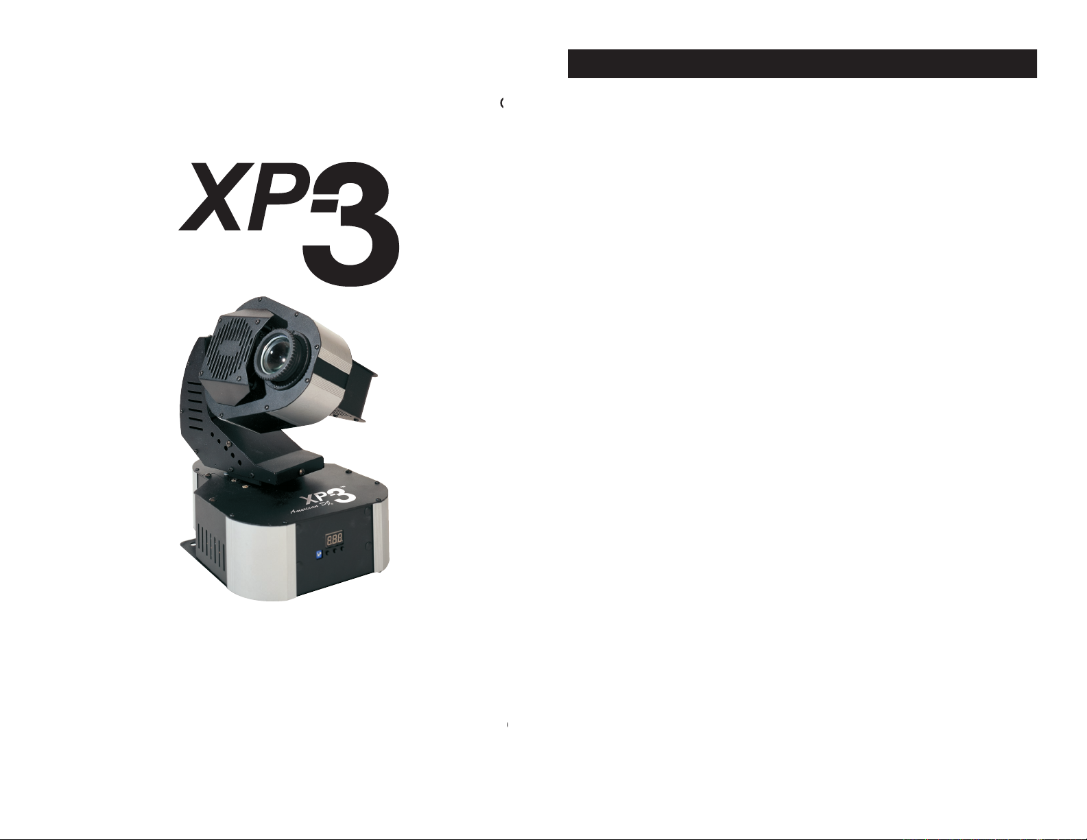
Thank you for purchasing the XP-3™ by American DJ
damage that may have occurred during shipping. If the carton appears
to be damaged, carefully inspect your xture for any damage and be
the case damage has been found or parts are missing, please contact
The XP-3™ is a unique intelligent fixture with a rotat-
MINI/C
American DJ
provides a toll free customer sup-
Voice:
Warning!
To prevent or reduce the risk of electrical shock or re, do
There are no user serviceable parts inside this unit. Do not
your nearest American DJ
dealer.
XP-3™ General Information
©
American DJ Supply
®
- www.americandj.com - XP-3™ Instruction Manual Page 2
Page 2

American DJ
- www.americandj.com - XP-3™ Instruction Manual Page 3
355˚ Pan / 240˚ Tilt
Volume Sensitivity Knob
The XP-3™ carries a one year (365 days) limited warranty. Please
fill out the enclosed warranty card to validate your purchase. All
322-6337
XP-3™ Safety Precautions
American DJ
- www.americandj.com - XP-3™ Instruction Manual Page 4
This unit may blow a fuse if the maximum allotted
wise instructed by an authorized American DJ
®
service technician. Use
To reduce the risk of electrical shock or re, do not expose this unit
the electrical cord. This prong is used to reduce the risk of electrical
Always be sure to mount this unit in an area that will allow proper
ventilation. Allow about 6” (15cm) between this device and a wall
This unit is intended for indoor use only, use of this product outdoors
voids all warranties
Always mount this unit in safe and stable matter
the manufacturer. See page 7 for cleaning details
The fixture should be serviced by qualified service personnel when:
A. The power-supply cord or the plug has been damaged.
marked change in performance.
XP-3™ Features
XP-3™ Product Registration
Page 3
Before plugging your unit in, be sure the source
voltage in your area matches the required voltage for your American
XP-3.™ Because line voltage may vary from venue to venue,
you should be sure your unit voltages matches the wall outlet voltage
A DMX controller sends DMX data instructions from
the controller to the fixture. DMX data is sent as serial data that
travels from fixture to fixture via the DATA “IN” and DATA “OUT” XLR
terminals located on all DMX fixtures (most controllers only have a
different manufactures to be linked together and operate from a single
To ensure proper DMX data transmission, when using several DMX
fixtures try to use the shortest cable path possible. The order in which
fixtures are connected in a DMX line does not influence the DMX
that unit, no matter where it is located in the DMX chain.
The XP-3 can be controlled via DMX-512 proto-
XP-3™ is a ve channel DMX unit. The DMX
data input and data output (Figure 1). If you are
two conductor shielded cable (This cable may be
daisy chained and can not be split.
©
American DJ
®
- www.americandj.com - XP-3™ Instruction Manual Page 6
©
American DJ
®
- www.americandj.com - XP-3™ Instruction Manual Page 5
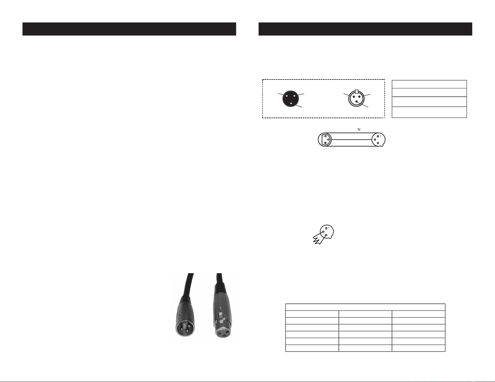
3-PIN XLR
3
3
COMMO
3-PIN XLR
XP-3™ Set Up
XLR Male Socket
XLR Pin Con guration
3 Hot
2 Cold
2 Cold
3 Hot
XLR Female Socket
Special Note: Line Termination.
When longer runs of cable are
2
3
Te
educes
signal
e
and
avoids
signal
transm iss ion
s
and
always
advisable
to
connect
a
terminal,
Ohm
W)
and
3
+)
of
the
fixture.
Be sure to follow gure three when making your own cables.
to come in contact with the XLR’s outer casing. Grounding the shield
5-Pin XLR DMX Connectors.
these adaptors are readily available at most electric stores. The chart
5-Pin XLR Male (In)
3-Pin XLR Female (Out)
3-Pin XLR to 5-Pin XLR Conversion
XP-3™ Set Up
Page 4
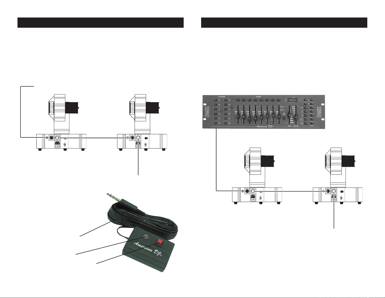
XP-3™ Linking
Your xture
with up to 4 units when daisy-chained together in a master-slave con-
guration. Any unit can function as either a “Master Unit” or a “Slave
To next XP-3™ if applicable
versal DMX controller to access the different traits associated with the
XP-3. A reference of different DMX traits is printed on page 21 of this
30 Foot Extension Cable
To next DMX unit or terminate.
©
American DJ
®
- www.americandj.com - XP-3™ Instruction Manual Page 7
©
American DJ
®
- www.americandj.com - XP-3™ Instruction Manual Page 8
XP-3™ Linking
Page 5

American DJ
- www.americandj.com - XP-3™ Instruction Manual Page 10
American DJ
- www.americandj.com - XP-3™ Instruction Manual Page 9
XP-3™ Controls and Functions
TOP
3
This is a fully focusing high quality lens. Focus the lens by manually
turning the lens in a clockwise or counter-clockwise direction until the
XLR Output Jack -
This jack is used to transmit the incoming DMX signal to another DMX
xture, or transmit a Master/Slave signal to the nest XP-3™ in the
jack if it is the last unit in the chain. See
“Terminator”
on page 7.
XLR Input Jack -
This jack is used to accept an incoming DMX signal (from a universal
XP-3™) signal.
This jack is for use with the optional
your manufactures warranty!
The power connection uses an I.E.C. type connector, use only a power
this unit to a power outlet that matches the printed power label on the
This housing stores the 5 amp GMA protective fuse. Always
wise instructed, by
®
service technician.
This thumb screw holds the lamp socket assembly cover (16) into
This thumb screw holds the lamp socket cover (16) into place.
XP-3™ Controls and Functions
Page 6

This knob adjust the audio sensitivity of the internal microphone (10).
Turning the sensitivity knob in the clockwise direction will increase the
will decrease the xture’s sensitivity to sound.
This microphone receives external low frequencies to trigger the unit in
These vents are used to allow proper cooling. Keep the vents clean.
failure.
Option Switches -
These are used to access two special functions:
TILT value. Up will become down and vice versa.
Function Buttons -
These buttons serve two functions. When the unit is to be used as the
XP-3™ Controls and Functions
American DJ
- www.americandj.com - XP-3™ Instruction Manual Page 12
©
American DJ
®
- www.americandj.com - XP-3™ Instruction Manual Page 11
Dipswitch Functions
1 2
ON
1 : Pan Inverted
2 : Tilt Inverted
5 1 2
Function Buttons Key
1 2 3
1 Function Key : F01 And F02 And DMX Address Change Key
2 Up Key : DMX Address Up Counter
3
Down Key : DMX Address Down Counter
The XP-3
may be operated in three different modes:
The unit will react to sound, chasing through
the several built in programs. You can also use the optional MINI/C
You can daisy chain up to 16 units together
to get a synchronized light show that will react to sound chasing
through several built in programs. You can also use the optional
This function will allow you to control each
the American DJ® DMX Operator™ or Show Designer.
This function allows a
traits and will only run to the units built-in programs.
To activate the Sound-Active mode, use the function button to
The unit will now react to the low frequencies of music via the inter-
3.
Adjust the audio sensitivity knob on the side of the unit to make the
Turning the sensitivity knob in
the clockwise direction will increase the sensitivity, turning the knob
Master/Slave Settings
F 0 1
F 0 2
Master
Small Pattern On Sound Active
Big Pattern On Sound Active
XP-3™ Operation
Page 7

©
American DJ Supply
®
- www.americandj.com - XP-3™ Instruction Manual Page 14
©
American DJ Supply
®
- www.americandj.com - XP-3™ Instruction Manual Page 13
XP-3™ Operation
tivity to sound.
4
The optional
MINI/C Blackout Controller
Note: Stand-Alone operation require sound to activate! The units will
blackout in this mode to conserve bulb life when there is no sound pres-
This function will
function does not allow individual control of the DMX traits and will only
ve and six, daisy chain your units together via the XLR connectors
the chain (master) will use the female XLR connector only. The last
3.
the unit will be used in. A large program type will use programs
that cover a wide area and small program type will use programs
that cover a narrow area.
4.
Adjust the audio sensitivity knob on the side of the unit to make the
Turning the sensitivity knob in
the clockwise direction will increase the sensitivity, turning the
The optional
function for blackout.
Note: Master-Slave operation require sound to activate! The units will
blackout in this mode to conserve bulb life when there is no sound pres-
This function allows you to use a universal
controller such
DMX Operator™ or
the freedom to create unique and customized programs tailored to
your specific individual needs.
The XP-3™ uses five DMX channels. Channel one controls pan,
the different DMX traits in depth.
To control your fixture in DMX mode, follow the set-up procedures
Master/Slave Settings
F 0 1
F 0 2
0 0 1
0 0 6
0 0 6
Master
Slave 1
Slave 2
Slave 3
Small Pattern On Sound Active
Big Pattern On Sound Active
Address 01
Address 06
Address 06
XP-3™ Operation
Page 8

with your DMX controller.
3.
traits.
This will allow you to create your own programs.
When using a DMX controller and setting up for DMX operation
follow the DMX addressing procedure in your controller’s manual.
All fixtures must follow a specific DMX addressing protocol for
with your DMX controller.
the last fixture.
XP-3™ Operation XP-3™ DMX Traits
The chart below details the DMX traits in depth. The individual trait
0
2550335
CHANNEL 1
255
00
00
00
255
TILT
CHANNEL 2
00
255
GOBO/COLOR
CHANNEL 3
DMX TRAITS
XP-3
PAN
240
00
240-255
00-15 Large White Spot
16-23
24-31
Gobo1 -
Red
32-39
Gobo2 - Blue
40-47
Gobo3 - Gree
n
48-55
Gobo4 - Yellow
56-63
Gobo5 - Lt. Blue
64-71
Gobo6 - Orange
72-79
Gobo7 - Red / Green
80-87
Gobo8 - Purpl
e
88-95
Gobo9 - Red / Green /
Yellow / Lt. Blue
96-103
Go
b
o
10
-
W
h
it
e
104-111
Gobo 11 - Lt. Blue
112-11
9
Gobo12 - Ye
llow
120-127
Gobo13 - Lt. Blue / Yello
w
128-135
Gobo14 - Orange
136-143
Gobo15 - P
ink
Gobo17 -
Dk. Blue144-151
Gobo16 - Gree
n
Large White Spot
152-239 Rotation
Fast - 23
9
Slow - 152
00
00
STROBE / SHUTTER
255
CHANNEL 5
Strobe
16-239
240-255
Open
239
152
Close
01-15
16
23
9
Speed Slow 2 fps -16
Speed Fast 10 fps -239
G2 COLOR / OBO STROBE
Speed Slow 1 fps - 255
CHANNEL 4
255
Any Color/Gobo Up
129-255
Speed Fast 7 fps - 129
Speed Fast 7 fps -128
Any Color/Gobo Down
01-128
Speed Slow 1 fps - 01
Stop
00
00
Lamp Off
243
American DJ
- www.americandj.com - XP-3™ Instruction Manual Page 16
American DJ
- www.americandj.com - XP-3™ Instruction Manual Page 15
2 Color Strobe Function:
This features allows two adjacent Color/
will work with any two color/gobo combination that next to each other
The XP-3 ships with a built-in rigging point and two large holes in the
xture by two large Phillips screws. When the rigging point is not to be
XP-3™ can be mounted to a wall or may hung from truss.
XP-3™ Mounting
Page 9

American DJ
- www.americandj.com - XP-3™ Instruction Manual Page 18
©
American DJ
®
- www.americandj.com - XP-3™ Instruction Manual Page 17
the fixture operates (I.e. smoke, fog residue, dust, dew). In heavy club
3.
30-60 days.
Always be sure to dry all parts completely before plugging the unit
Trouble Shooting:
with solutions.
3.
4.
Tapping on the microphone, quiet or high pitched sounds may not
is not set to the minimum
XP-3™ Gobo Wheel Layout
This chart details the gobo patterns as well as the gobo placement on
the internal wheel.
the wheel rotation.
XP-3™ Cleaning
XP-3™ Trouble Shooting
Page 10

with halogen lamps.
3.
the socket assembly.
4.
©
American DJ
®
- www.americandj.com - XP-3™ Instruction Manual Page 19
©
American DJ
®
- www.americandj.com - XP-3™ Instruction Manual Page 20
Always replace with the exact same type lamp and fuse,
technician.
Disconnect the unit’s main power supply.
the fuse. Remove the old fuse and discard it. Replace the fuse
with the same type. Insert the fuse holder back into it’s housing
Caution! Never attempt to change the lamp
while the fixture is plugged in. Always disconnect the main power and
Thumb Screw
Assembly
XP-3™ Halogen Lamp Warning
This fixture is fitted with halogen lamps which
XP-3™ Fuse & Lamp Replacement
XP-3™ Fuse & Lamp Replacement
Page 11

©
American DJ® - www.americandj.com - XP-3™ Instruction Manual Page 21
American DJ
- www.americandj.com - XP-3™ Instruction Manual Page 22
A. American DJ
®
hereby warrants, to the original purchaser, American DJ
®
products to be
free of manufacturing defects in material and workmanship for a period of 1 year (365 days)
from the date of purchase. This warranty shall be valid only if the product is purchased
within the United States of America, including possessions and territories. It is the owner’s
time service is sought.
®
factory. All shipping
charges must be pre-paid. If the requested repairs or service (including parts replacement)
will pay return shipping charges only
to a designated point within the United States. If the entire instrument is sent, it must be
shipped in its original package. No accessories should be shipped with the product. If any
shall have no liability whatsoever
for loss of or damage to any such accessories, nor for the safe return thereof.
concludes, after inspection, affects the reli-
American DJ
factory unless prior written authorization was issued to purchaser by Ameri-
can DJ
or periodic check-up. During the period speci ed above, American DJ
will replace defec-
tive parts at its expense, and will absorb all expenses for warranty service and repair labor
®
were manufactured after January 1, 1990, and bear identifying marks to that effect.
reserves the right to make changes in design and/or improvements upon
sory supplied with products described above. Except to the extent prohibited by applicable
in connection with this product, including
warranties of merchantability or tness, are limited in duration to the warranty period set
forth above. And no warranties, whether expressed or implied, including warranties of mer-
chantability or tness, shall apply to this product after said period has expired. The con-
sumer’s and or Dealer’s sole remedy shall be such repair or replacement as is expressly
®
be liable for any loss or
damage, direct or consequential, arising out of the use of, or inability to use, this product.
Products and
supersedes all prior warranties and written descriptions of warranty terms and conditions
The charts below details the Master/Slave setting for Master/Slave
Dipswitch Functions
1 2
ON
1 : Pan Inverted
2 : Tilt Inverted
5 1 2
Function Buttons Key
1 2 3
1 Function Key : F01 And F02 And DMX Address Change Key
2 Up Key : DMX Address Up Counter
3
Down Key : DMX Address Down Counter
Master/Slave Settings
F 0 1
F 0 2
0 0 1
0 0 6
0 0 6
Master
Slave 1
Slave 2
Slave 3
Small Pattern On Sound Active
Big Pattern On Sound Active
Address 01
Address 06
Address 06
XP-3™ Master/Slave Quick Reference Chart
XP-3™ Warranty
Page 12

©American DJ®
American DJ Group of Companies World Headquarters:
Tel: 323-582-2650 Fax: 323-582-2610
Web: www.americandj.com E-mail: info@americandj.com
ZB-JCR H5 15v/150w
Voltage*:
Weight:
Yes
Working Position:
Any Safe, Secure Position
Warranty:
* Voltage is preset at the factory and is not user selectable.
Speci cations and improvements in the design
prior written notice.
American DJ
- www.americandj.com - XP-3™ Instruction Manual Page 23
 Loading...