

Page 1
SPECIFICATIONS:
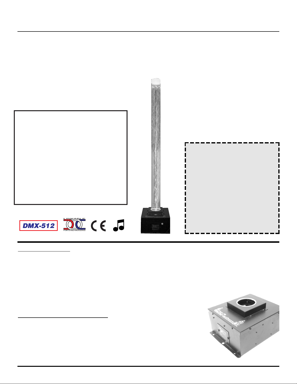
MODEL - Water Column™
Weight: 16 lbs.Without water
Size: 53.5” x 11” x 10"
Lamps: EXN 12V 50W
Fuse: 3A
Supply Voltage: 120V
Tube capacity: Approx. 2.5 gal
Tube Dimensions: 48” X 3.25”
Colors: 8 plus White
American DJ
®
Assembly Instructions
Affordable Quality Lighting Products from American DJ® Los Angeles, CA. 90058 USA Page 1
CAUTION!
Read instructions before installing
or plugging unit in.
HALOGEN LAMP WARNING!
This fixture is fitted with halogen
lamps which are highly susceptible to damage if improperly handled. Never touch lamp with bare
fingers as the oil from your
hands will shorten lamp life.
Also, never move fixture until
lamp has had ample time to cool.
Remember, lamps are not covered under warranty conditions.
INTRODUCTION
Congratulations on your purchase of the American DJ Water Column/4™. This unique piece adds a
dazzling effect to Clubs, Bars, Bowling Centers, and Roller Rinks. The Water Column/4™ is an intelligent color changer that can be operate with a standard DMX controller or in sound active and stand
alone modes. This unit can be set to scroll through it’s 8 colors (plus white), or set to a particular color
through the use of a standard DMX controller such as the American DJ
DMX Operator™. This unit is sound active and the bubble intensity can
be adjusted.
ASSEMBL
Y INSTRUCTIONS
The Water Column/4™ is shipped in two boxes, one (1) box contains
the water tube and the other contains the water column base (see figure
1), warranty card, and owners manual. Carefully unpack the base and
water tube from their respective boxes.
Water Column/4
™
Figure 1
Page 2
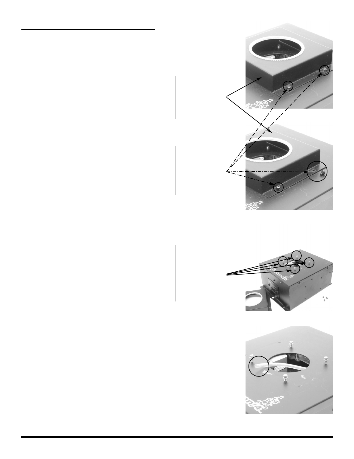
Begin assembly by removing the outer protective collar assembly. Remove the four (4) black,
phillips screws from tube collar located on the
top of water column base (see figures 2 and 3),
to remove the collar. Remove the collar assembly.
Affordable Quality Lighting Products from American DJ® Los Angeles, CA. 90058 USA Page 2
Figure 2
Figure 3
Figure 4
Removing the collar will expose four (4) more
brass screws that are used to secure the water
tube to the base, remove these four (4) brass
screws as well (see figure 4).
Outer Collar
Assembly
Remove Four
(4) Screws
ASSEMBLY INSTRUCTIONS CONT.
Step 1
Step 2
Step 3
Figure 5
When all the screws have been removed locate
the plastic air tube located inside the center
hole of the water base and pull it out. (see figure 5).
Remove Four
(4) Screws
Page 3
Affordable Quality Lighting Products from American DJ®Los Angeles, CA. 90058 USA Page 3
Figure 6
Figure 8
Figure 7
Figure 9
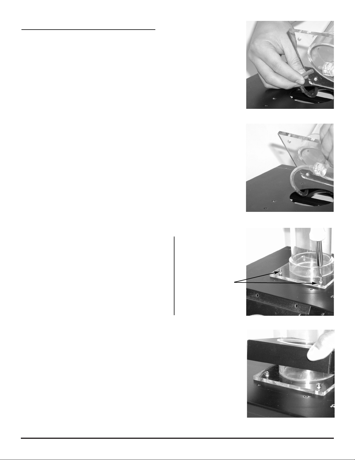
Connect the air hose to water column tube by
inserting the rubber tube into the plastic nipple
located on the bottom of the tube (see figure 6).
Step 4
ASSEMBLY INSTRUCTIONS CONT.
Figure seven (7) shows a properly inserted rubber
tube. Be sure that the rubber tube is seated completely unto the tube’s plastic nipple.
After properly inserting the rubber tube in the
the tubes plastic nipple, set the tube upright on
the water tube base. Align the screw hole on the
tube and the base to screw the base and the
tube together. Be sure to use the same brass
screws the were included with your fixture.
Step 5
Step 6
Step 7
Remove the water tube’s protective white cover
located on the top of the water tube to replace the
tube assembly collar. Carefully replace the tube
collar by sliding it through the top of tube.
Caution: To
avoid damage
to your water
tube be sure not
to over tighten
the securing
screws.!
Page 4

Figure 10
Secure the collar with the four (4) included black,
phillips screws.
Step 8
ASSEMBLY INSTRUCTIONS CONT.
OPERATING INSTRUCTIONS
PROPER WATER INST
ALLATION
Due to the excessive weight of water filled in the tube, we suggest that you place the water column in
it’s final position before filling the tube with water. This may avoid damage to the tube that may be
caused by the strain of the excessive weight caused by the water in the tube.
Once you have placed your water column in your desired position, fill the water tube only with dis-
tilled water to avoid water discoloration and oder. DO NOT FILL the tube pass the maximum fill
line level at the top of the tube, doing so may spurt water out caps breather hole. Use algae
tablets available where fish aquariums are sold is also highly recommended to avoid mildew and
oder.
Once you have filled the tube replace the protective white cap. The cap has a breather hole punched
out in the center of it, be sure never to restrict this hole to avoid possible damage to the unit’s air
pump.
If it becomes necessary to move your water column after it has been filled with water, be sure not to
lift the assembly by the tube or you may crack the tube. Always move your water column by grasping
the base of the unit.
Stand Alone (Sound Active):
This function allows you to operate an individual fixture to sound without the use of a controller. In
this mode the unit scroll through its’ internal programs to the beat of the music. When there is no
sound source for a period of ten (10) seconds the fixture will automatically go into blackout mode.
When there is no sound source for more than 30 seconds the fixture will automatically shut down the
lamp output to prolong lamp life. The unit will continue to operate normally once a sound source has
been reintroduced.
To run a fixture in this mode: Be sure the unit is powered down. Set dip switch number 10 to the on
position and be sure that all others dip switches are set to the off position. Turn the power on. The
unit will take about 10 seconds to reset and then begin to react to low frequencies of a sound source.
Master/Slave: This function allows you to connect up to eight (8) units together and run them to
internal programs without the use of an external controller.
POWER SUPPL
Y:
Before plugging your unit in be sure the voltage in your area matches the required voltage for your
unit. The DMX Operator™ require a DC 9v 200mA power supply.
The DMX Operator™ is available in a 115v and 230v version. Because line voltage may vary from
venue to venue, you should be sure to plug your power supply into a matching wall outlet before
attempting to operate you controller.
Affordable Quality Lighting Products from American DJ®Los Angeles, CA. 90058 USA Page 4
Page 5

To run two (2) or more fixtures in this mode: Be sure all your units are powered down. Connect your
units together using the XLR connectors on the rear of the unit via standard, high quality, balanced
microphone cable. Be sure to daisy chain the fixture together. Do not try to “Y” or split your connections. The female XLR connector is the output connector and the male XLR connector is the input
connector. Once you have connected your units together, follow the dip switch chart on page 7/diagram 1 to assign the proper values to your fixtures. When you have set all the dip switches according
to the chart on page eight (8), turn all the power switches on. The units will all take about 10 seconds
to reset. After resetting the units will begin to react to first unit’s (master unit) internal programs.
Those programs in turn will be triggered by the low frequencies of a sound source.
When there is no sound source for a period of ten (10) seconds the fixture will automatically go into
blackout mode. When there is no sound source for more than 30 seconds the fixture will automatically shut down the lamp output to prolong lamp life. The unit will continue to operate normally once a
sound source has been reintroduced.
EL-1402/C Controller: The EL-1402/C is a 19 inch rackmount controller allows you to control several
of the water columns function without the expensive of a multifunctional DMX controller. The EL1402/C controller gives you several controller options; Blackout, Synchro Color, Random Color,
Strobe, Sweep, Random, or Manual. Blackout will terminate all light output. Synchro Color will scroll
the units to same color. Random Color will scroll individual units through different colors. Strobe will
produce a variety of strobe effects automatically. Sweep will change all the units colors in a sequential order. Random will operate your units in all four (4) modes automatically, triggered by sound. You
may also manually control your units to constantly maintain a specific color. When using the EL1402/C controller follow the dip switch chart on page 7/diagram 2 to assign the proper values to your
fixtures.
Please refer to the owners manual that is included with the EL-1402/C for a more detail description of
the controller, set-up, and operating instructions.
DMX Mode: Only Color may be controlled through DMX, not bubble flow.
Operating through a DMX controller give the user the freedom to create his/her own programs tailored to their own individual needs. This function also allows you to use your fixtures as spot lights.
This function will allow you to control each individual fixture’s traits with a standard DMX 512 controller such as the American DJ DMX Operator™ and Show Designer
TM
. The Water Column/4™ uses
one (1) DMX channel to operate. To run your fixture in DMX mode, plug in the fixture via the XLR
connections to any standard DMX controller. - Follow the set-up specifications that come with your
DMX controller. Follow the dip switch chart on page 7/diagram 2 to assign the proper DMX values for
your first 16 fixtures.
Data Cable (DMX Cable) Requirements: Your fixture and your controller require a standard
3-pin XLR connector for data input and output. If you are making your own cables be sure to use
standard two conductor shielded cable and follow the pin configuration as described in the charts
below. Your cables should be made with a male and female XLR connector on either end of the
cable. Also remember that DMX cable must be daisy chained and can not be “Y”ed or split.
Affordable Quality Lighting Products from American DJ®Los Angeles, CA. 90058 USA Page 5
XLR MALE SOCKET
1 EARTH 2 COLD
HOT 3
XLR FEMALE SOCKET
1 EARTH2 COLD
3 HOT
Figure 2
XLR Pin Configuration:
Pin 1 = Shield
Pin 2 = Data Compliment (negative)
Pin 3 = Data True (positive)
Page 6

Notice: Do not use the ground lug on the XLR connector. Do not connect the shield conductor
to the ground lug or allow the shield conductor to come in contact with XLR outer casing. Grounding
the shield could cause a short circuit and erratic behavior.
Line Terminator: When longer runs of cable are used you may need to use a terminator on the
last unit to avoid erratic behavior. A terminator is a 90 - 120 ohm 1/4 watt resistor which is connected
between pins 2 and 3 or a male XLR connector (DATA + and DATA -). This unit is inserted in the
female XLR connector of the last unit in your daisy chain to terminate the line. Terminators may be
purchased or you can make one by soldering a 90-120 ohm 1/4 watt resistor between pins two (2)
and three (3) of a male XLR Plug.
CAUTION: The base of the fixture will get hot if it is operated for a long period of time. For optimum
performance, use a 30 min ON/ 10 min OFF duty cycle. Allow the unit to cool before attempting to
replace the bulb. Never open the unit when it is in use. Always disconnect the main power before servicing or replacing lamp. Refer all service issue to authorized American DJ dealer.
Lamp replacement: Disconnect the units main power supply
before attempting any type of service. Please allow ample time for the
unit to cool down before handle the unit. With the power disconnected
unscrew the two (2) thumb screw located on the rear of the unit.
Gently pull out the lamp try. Remove and replace the lamp.
CAUTION: Always replace with the exact same type lamp and fuse
unless otherwise specified by an authorized American DJ service
technician.
Customer Support: American DJ provides a toll free customer
support line, to provide set up help and to answer any question should you
encounter problems during your set up or initial operation. You may also
visit us on the web at www.americandj.com for any comments or suggestions.
Service Hours Monday through Friday are 10:00 a.m. to 5:00 p.m. Pacific
Time.
Voice (800) 322-6337
Fax (323) 582-2610
E-mail: support@americandj.com
DMX Traits:
Figure 12 list the traits for each DMX value. Use this charts to select your
desired color when using a DMX controller or programming.
Affordable Quality Lighting Products from American DJ®Los Angeles, CA. 90058 USA Page 6
Figure 11
WHITE
COLOR
CHANGE
SPEED
FLASH
SPEED
WHITE
MAGENTA
PINK
AMBER
GREEN
ORANGE
YELLOW
BLUE
LIGHT
GREEN
WHITE
BLACKOUT
255
254
160
159
86
78
72
60
54
44
37
26
18
9
0
Figure 12
Remove Thumb Screws To Access Lamp
Page 7

Diagram 1 DMX & EL-1402/C Controller
Dip Switch Settings
Diagram 2 Stand Alone Master/Slave
Dip Switch Settings
MASTER
123 54791086
ON
11
12
123 54791086
ON
11
12
123 54791086
ON
11
12
123 54791086
ON
11
12
SLAVE 1
SLAVE 2
SLAVE 3
4 UNITS
123 54791086
ON
11
12
123 54791086
ON
11
12
123 54791086
ON
11
12
123 54791086
ON
11
12
MASTER
SLAVE 1
SLAVE 2
SLAVE 3
SLAVE 4
SLAVE 5
SLAVE 6
SLAVE 7
123 54791086
ON
11
12
123 54791086
ON
11
12
123 54791086
ON
11
12
123 54791086
ON
11
12
8 UNITS
Affordable Quality Lighting Products from American DJ® Los Angeles, CA. 90058 USA Page 7
123 54791086
ON
11
12
123 54791086
ON
11
12
123 54791086
ON
11
12
123 54791086
ON
11
12
SLAVE 1
SLAVE 2
SLAVE 3
SLAVE 4
SLAVE 5
SLAVE 6
SLAVE 7
SLAVE 8
123 54791086
ON
11
12
123 54791086
ON
11
12
123 54791086
ON
11
12
123 54791086
ON
11
12
SLAVE 9
123 54791086
ON
11
12
SLAVE 10
123 54791086
ON
11
12
SLAVE 11
123 5479
10
86
ON
11
12
SLAVE 12
123 54791086
ON
11
12
SLAVE 13
123 54791086
ON
11
12
SLAVE 14
123 54791086
ON
11
12
SLAVE 15
123 54791086
ON
11
12
SLAVE 16
123 54791086
ON
11
12
 Loading...