

Page 1
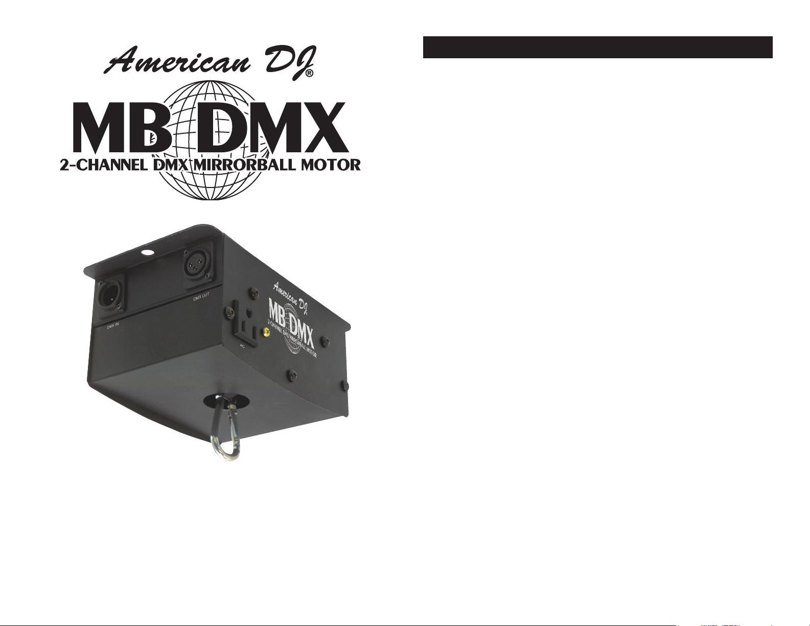
MB DMX™ General Information
Unpacking.....................................................................................3
Introduction..................................................................................3
Customer Support.............................................................................3
Safety Precautions...............................................................................4
Features.........................................................................................5
Registration..............................................................................5
Set-Up
DMX Linking...................................................................................6
Data Cable Requirements............................................................6
Termination................................................................................7
5 Pin Conversion.........................................................................7
Linking...........................................................................................8
Operating Modes
Stand Alone.................................................................................10
Master/Slave..................................................................................10
DMX ......................................................................................11
Mounting...................................................................................12
Breaker Reset.....................................................................................12
DMX Traits......................................................................................13
Master/Slave Quick Reference Chart.................................................14
Warranty.........................................................................................15
Specifications..............................................................................16
Revised 2/03
User Instructions
American DJ®
4295 Charter Street
Los Angeles Ca. 90058
www.americandj.com
©American DJ Supply® - www.americandj.com - MB DMX™ Instruction Manual Page 2
Page 2

MB DMX™ General Information
MB DMX™ Safety Precautions
General Instructions: To optimize the performance of this product,
please read these operating instructions carefully to familiarize yourself with the basic operations of this unit. These instructions contain
important safety information regarding the use and maintenance of
this unit. Please keep this manual with the unit, for future reference.
Unpacking: Thank you for purchasing the MB DMX™ by American
DJ®. Every MB DMX™ has been thoroughly tested and has been
shipped in perfect operating condition. Carefully check the shipping
carton for damage that may have occurred during shipping. If the
carton appears to be damaged, carefully inspect your xture for any
damage and be sure all accessories necessary to operate the unit has
arrived intact. In the case damage has been found or parts are missing, please contact our toll free customer support number for further
instructions. Do not return this unit to your dealer without rst contacting customer support.
Introduction: The MB DMX™ is a unique intelligent mirror ball motor
that may be operated in three modes; DMX-512, Stand-Alone, or Master/
Slave. The MB DMX™ allows you to control the operation of a mirror ball
motor as well as the lamps via DMX operation. You may also link several MB DMX™ motors together to obtain universal speed and rotation.
An optional MINI/C black out controller may be purchased separately.
Customer Support: American DJ® provides a toll free customer
support line, to provide set up help and to answer any question should
you encounter problems during your set up or initial operation. You
may also visit us on the web at www.americandj.com for any comments or suggestions. Service Hours are Monday through Friday 9:00
a.m. to 5:00 p.m. Pacic Standard Time.
Voice: (800) 322-6337
Fax: (323) 582-2610
E-mail: support@americandj.com
Safety Issues:
• To reduce the risk of electrical shock or re, do not expose this
unit rain or moisture
• Do not spill water or other liquids into or on to your unit
• Do not attempt to operate this unit if the power cord has been
frayed or broken
• Do not attempt to remove or break off the ground prong from
the electrical cord. This prong is used to reduce the risk of
electrical shock and re in case of an internal short
• Disconnect from main power before making any type of connection
• Do not remove the cover under any conditions. There are no user
serviceable parts inside
• Never plug this unit in to a dimmer pack
• Always be sure to mount this unit in an area that will allow proper
ventilation. Allow about 6” (15cm) between this device and a wall
• Do not attempt to operate this unit, if it becomes damaged
• This unit is intended for indoor use only, use of this product
outdoors voids all warranties
• During long periods of non-use, disconnect the unit’s main power
• Always mount this unit in safe and stable matter
• Power cords should be routed so they are not likely to be walked
on, pinched by items placed upon or against them.
• Heat -The appliance should be situated away from heat sources
such as radiators, heat registers, stoves, or other appliances
(including amplifiers) that produce heat.
• The fixture should be serviced by qualified service personnel when:
A. The power-supply cord or the plug has been damaged.
B. Objects have fallen, or liquid has been spilled into the appliance.
C. The appliance has been exposed to rain or water.
D. The fixture does not appear to operate normally or exhibits a
marked change in performance.
Warning! To prevent or reduce the risk of electrical shock or re, do
not expose this unit to rain or moisture.
Caution! There are no user serviceable parts inside this unit. Do not
attempt any repairs yourself, doing so will void your manufactures
warranty. In the unlikely event your unit may require service please
contact your nearest American DJ® dealer.
©American DJ® - www.americandj.com - MB DMX™ Instruction Manual Page 3
©American DJ® - www.americandj.com - MB DMX™ Instruction Manual Page 4
Page 3
MB DMX™ Features
MB DMX™ Set Up
• Micro-Stepping Motors for Smooth Rotation
• Uses Two DMX Channels
• DMX-512 Protocol Compatible
• Variable Head Rotation Speed
• Built-In Rigging Point
• Stand-Alone or Master/Slave Operation
• Linkable
• Two Built-In DMX Controlled AC Power Sockets
• Heavy Duty Mirror Ball Motor
• Rated for 20” Mirror Balls
• Optional Mini/C Blackout Controller
MB DMX™ Product Registration
The MB DMX™ carries a one year (365 days) limited warranty.
Please fill out the enclosed warranty card to validate your purchase.
All returned service items whether under warranty or not, must be
freight pre-paid and accompany a return authorization (R.A.) number. The R.A. number must be clearly written on the outside of the
return package. A brief description of the problem as well as the R.A.
number must also be written down on a piece of paper and included
in the shipping container. If the unit is under warranty, you must provide a copy of your proof of purchase invoice. You may obtain a R.A.
number by contacting our customer support team on our toll free
customer support number at (800) 322-6337. All packages returned
to service not displaying a R.A. number on the outside of the package will be returned to the shipper.
Power Supply: Before plugging your unit in, be sure the source
voltage in your area matches the required voltage for your American
DJ® MB DMX.™ Because line voltage may vary from venue to venue,
you should be sure your unit voltages matches the wall outlet voltage
before attempting to operate you xture.
DMX-512: DMX is short for Digital Multiplex. This is a universal pro-
tocol used as a form of communication between intelligent fixtures
and controllers. A DMX controller sends DMX data instructions from
the controller to the fixture. DMX data is sent as serial data that travels from fixture to fixture via the DATA “IN” and DATA “OUT” XLR terminals located on all DMX fixtures (most controllers only have a DATA
“OUT” terminal).
DMX Linking: DMX is a language allowing all makes and models of
different manufactures to be linked together and operate from a single controller, as long as all xtures and the controller are DMX compliant. To ensure proper DMX data transmission, when using several
DMX fixtures try to use the shortest cable path possible. The order
in which fixtures are connected in a DMX line does not influence the
DMX addressing. For example; a fixture assigned a DMX address of 1
may be placed anywhere in a DMX line, at the beginning, at the end,
or anywhere in the middle. When a fixture is assigned a DMX address
of 1, the DMX controller knows to send DATA assigned to address 1
to that unit, no matter where it is located in the DMX chain.
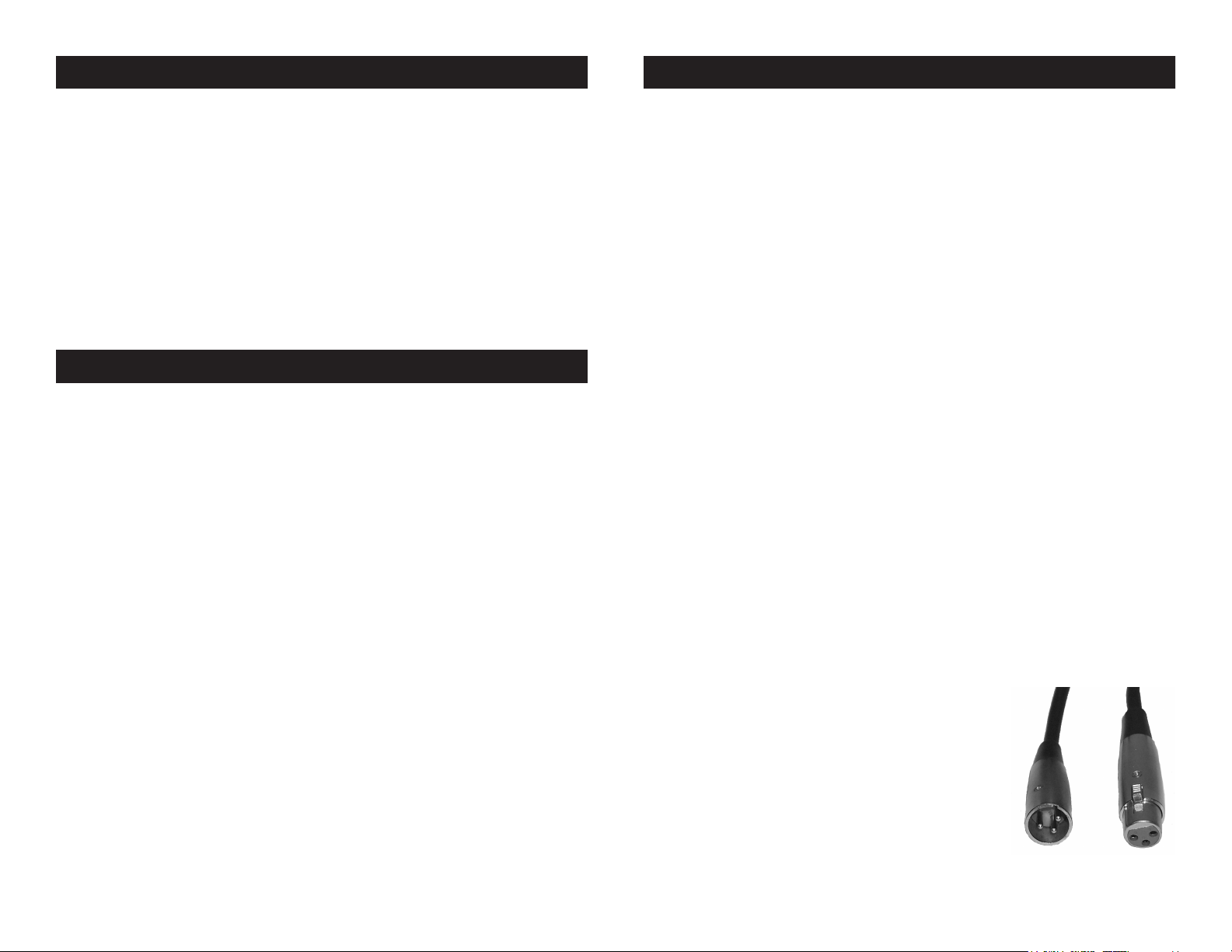
Data Cable (DMX Cable) Requirements (For DMX and Master/
Slave Operation): The MB DMX™ can be controlled via DMX-512
protocol. The American DJ® MB DMX™ is a two channel DMX unit.
The DMX address is set on the side panel using the dipswitches. Your
unit and your DMX controller require a standard
3-pin XLR connector for data input and data
output (Figure 1). If you are making your own
cables, be sure to use standard two conductor
shielded cable (This cable may be purchased at
almost all pro sound and lighting stores). Your
cables should be made with a male and female
XLR connector on either end of the cable.
Also remember that DMX cable must be daisy
chained and can not be split.
©American DJ® - www.americandj.com - MB DMX™ Instruction Manual Page 6©American DJ® - www.americandj.com - MB DMX™ Instruction Manual Page 5
Figure 1
Page 4

DMX IN DMX OUT
DMX IN DMX OUT
DMX512 IN
3-PIN XLR
REMOTE
CONTROL
INPUT
POWER
INPUT OUTPUT
SOUND
REMOTE
CONTROL
INPUT
POWER
INPUT OUTPUT
SOUND
REMOTE
CONTROL
INPUT
POWER
INPUT OUTPUT
DMX512
DMX+,DMX-,COMMON
1
2
3
Terminatio n reduc es signal errors and
avo ids signa l tran smi ssi on pro ble ms
and interferenc e. It is always advisable
to connect a DMX terminal, (Resistance
120 Ohm 1/4 W) between PIN 2 (DMX-)
and PIN 3 ( DMX +) of the last fixture.
1
2
3
1
2
3
DMX +
DMX -
COMMON
DMX512 OUT
3-PIN XLR
MB DMX™ Set Up
POWER
SOUND
REMOTE
CONTROL
INPUT
POWER
INPUT OUTPUT
1
2
3
Terminatio n reduc es signal errors and
avo ids signa l tran smi ssi on pro ble ms
and interferenc e. It is always advisable
to connect a DMX terminal, (Resistance
120 Ohm 1/4 W) between PIN 2 (DMX-)
and PIN 3 ( DMX +) of the last fixture.
MB DMX™ Linking
Notice: Be sure to follow gure three when making your own cables.
Do not use the ground lug on the XLR connector. Do not connect the
cable’s shield conductor to the ground lug or allow the shield conductor to come in contact with the XLR’s outer casing. Grounding the
shield could cause a short circuit and erratic behavior.
XLR Male Socket
1 Ground
2 Cold
3 Hot
Figure 2
Special Note: Line Termination.
used, you may need to use a terminator on the last unit to avoid erratic
behavior. A terminator is a 90-120 ohm 1/4 watt resistor which is connected between pins 2 and 3 of a male XLR connector (DATA + and
DATA -). This unit is inserted in the female XLR connector of the last
unit in your daisy chain to terminate the line. Using a cable terminator
(ADJ part number ZDMX/T) will decrease the possibilities of erratic
behavior.
XLR Female Socket
2 Cold
XLR Pin Conguration
1 Ground
3 Hot
Pin 1 = Ground
Pin 2 = Data Compliment (negative)
Pin 3 = Data True (positive)
Figure 3
When longer runs of cable are
Master/Slave Linking:
For a more dramatic effect, link several MB DMX™ together. Your
xture comes with built-in programs. These programs are designed
to work with up to 4 units when daisy-chained together in a masterslave conguration. Any unit can function as either a “Master Unit” or
a “Slave Unit.” Link the units together using standard DMX cable as
described on pages 6 and 7.
Optional MINI/C blackout controller
To next MB DMX™ if applicable
5-Pin XLR DMX Connectors:
connectors for DATA transmission in place of 3-pin. 5-pin XLR xtures
may be implemented in a 3-pin XLR DMX line. When inserting standard 5-pin XLR connectors in to a 3-pin line a cable adaptor must be
used, these adaptors are readily available at most electric stores. The
chart below details a proper cable conversion.
Data Compliment (- signal)
Optional MINI/C:
The optional MINI/C controller
allows all units linked together
Figure 4
Some manufactures use 5-pin XLR
to blackout. This unit will only
blackout the xtures and will not
change or select different programs.
3-Pin XLR to 5-Pin XLR Conversion
Conductor 5-Pin XLR Male (In)3-Pin XLR Female (Out)
Ground/Shield
Data True (+ signal)
Not Used
Not Used
©American DJ® - www.americandj.com - MB DMX™ Instruction Manual Page 7 ©American DJ® - www.americandj.com - MB DMX™ Instruction Manual Page 8
Pin 1
Pin 2
Pin 3
Pin 1
Pin 2
Pin 3
Do Not Use
Do Not Use
30 Foot Extension Cable
Blackout Indicator
Blackout Button
Page 5

DMX IN DMX OUT
DMX IN DMX OUT
MB DMX™ Linking
DMX Linking:
DMX function allows independent control of each xture. Use any
universal DMX controller to access the different traits associated with
the MB DMX. A reference of different DMX traits is printed on page 21
of this manual. Link the units together using standard DMX cable as
described on pages 5 and 6.
MB DMX™ Operation
Operating Modes: The MB DMX
™
may be operated in three different modes. Always be sure to disconnect the power supply after
changing the operating mode, this allows the unit to reset to the new
operating mode. Failure to disconnect the power supply after changing the operating mode may cause the unit to function improperly.
• Stand alone mode - The unit will rotate to the pre-defined speed
set with the dip switches. You can also use the optional MINI/C
remote to control a blackout function.
• Master/Slave mode - You can daisy chain up to 16 units together
to get synchronized motor rotation. The motor will rotate to a preset
speed. You can also use the optional MINI/C remote to control a
blackout function.
• DMX control mode - This function will allow you to control each
unit’s individual traits with a standard DMX 512 controller such as the
American DJ® and LSC® DMX Operator™ or Show Designer.
™
Stand-Alone Operation: This function allows a single unit to oper-
ate to any of the presets using the dipswitches. Only use this function
when running a single unit, or when running several units as individuals. Please note this function does not allow individual control of the
DMX traits.
1. To activate the Stand-Alone mode, locate the dipswitches on the
side of the unit and flip dipswitch 10 to the “on” position.
2. Follow the dipswitch chart on page 14 to select a preset speed
and to control mirror ball rotation direction.
3. Attach the mirror ball to the motor and connect main power.
4. The optional MINI/C Blackout Controller may be used in this
mode to control blackout.
Master/Slave Operation: This function will allow you to link up to
16 units together without the use of an external controller. In Master/
To next DMX unit or terminate.
©American DJ® - www.americandj.com - MB DMX™ Instruction Manual Page 9 ©American DJ® - www.americandj.com - MB DMX™ Instruction Manual Page 10
Slave operation one unit will act as the controlling unit and the others
will react to the controlling units presets. Any unit can act as a Master
or as a Slave. Please note this function does not allow individual control of the DMX traits and will only run to the units built-in programs.
1. Using standard XLR microphone cables, as described on pages
six and seven, daisy chain your units together via the XLR connec-
Page 6

MB DMX™ Operation MB DMX™ Operation
tors on the rear of the units. Remember the Male XLR connector
is the input and the Female XLR connector is the output. The rst
unit in the chain (master) will use the female XLR connector only.
The last unit in the chain will use the male XLR connector only.
For longer cable runs we suggest a terminator at the last fixture.
2. Select a MB DMX to be the “master” unit. Locate the dipswitches
on the side of the unit and flip dipswitch 10 to the “on” position.
3. Follow the chart on page 14 to select a desired rotation speed
and direction. Be sure to note that this selection will be universal
throughout all motors in the chain.
4. For all other motors in the chain (slaves) located the dipswitches
on the side of the units and be sure dipswitch 10 is in the “off”
position.
5. Connect main power to all the motors and they will immediately
begin to rotate to the presets of the “master” unit.
6. The optional MINI/C Blackout Controller may be used with this
function for to stop motor rotation.
Universal DMX Control: This function allows you to use a univer-
sal DMX-512 controller such as the American DJ® DMX Operator™ or
Show Designer.™ to control rotation speed, rotation direction, and the
built-in power sockets (usually for lamps). Operating through a DMX
controller allows you the freedom to create unique and customized
programs tailored to your specific individual needs.
1. The MB DMX™ uses two DMX channels. Channel one controls
power sockets located on the side of the unit. Channel two
control the motor’s rotation speed and direction.
2. To control your motor in DMX mode, follow the set-up procedures
on pages 7 - 9 as well as the set-up specifications that are included
with your DMX controller.
3. Use the DMX controller’s faders to control the various DMX fixture
traits. A list of the traits is located on page 13.
4. This will allow you to create your own programs.
5. When using a DMX controller and setting up for DMX operation
follow the DMX addressing procedure in your controller’s manual.
All fixtures must follow a specific DMX addressing protocol for
proper operation in DMX mode.
6. For help operating in DMX operation consult the manual included
with your DMX controller.
7. For longer cable runs (more than a 100 feet) use a terminator on
the last fixture.
MB DMX™ Mounting
Mounting: The MB DMX™ ships with a built-in rigging point and
two large holes in the base of the unit (that are to be used for safety
cables). The rigging point is located on the bottom of the unit. This rigging point is secured to the xture by two large Phillips screws. When
the rigging point is not to be used and when the xture is shipped
from the manufacture, the point is shipped inverted (inside the bottom
of the unit). When the xture is to be hung by truss or other means,
please use the rigging point and secure the xture with safety cables.
Always be sure to rmly secure the rigging point to the unit. The MB
DMX ™ is to mounted in bottom-up position to a ceiling or may hung
from truss using a C-Clamp rated at 50 pounds or greater.
MB DMX™ Breaker Reset
This unit is equipped with a built-in safety breaker. This breaker is
designed to close the power circuit in the event of an internal short
or power surge. This will reduce the risk of electrical shock or re and
protect the circuitry. To reset the breaker, push the breaker button in
until you hear it “pop” back in to place. If the breaker continues to pop,
stop using the unit and contact our customer support team, the unit
may need to be returned for service.
©American DJ® - www.americandj.com - MB DMX™ Instruction Manual Page 12©American DJ® - www.americandj.com - MB DMX™ Instruction Manual Page 11
Page 7

MB DMX™ DMX Traits
C HANNE L 2
00
MO TO R S PE E D
255
00
12
8
01
12
7
129
255
Stop
Stop
C W Speed 5 rp m - 01
C W Speed 0.5 rpm - 12
7
C C W S pe ed 0.5r pm - 129
C C W S pe ed 5 rpm - 255
C HANNE L 1
255
LA MP
00
00
255
128
12
9
La mp O n
129-255
La mp O ff
00-128
MB-DMX DMX TRAITS
Dipswitch Function Settings
Dipswitches 1
~
8 Used to change the rotation speed during
Stand-Alone or Master/Slave mode
Master Motor Speed List
Switch
Speed
DIP1 DIP2 DIP3 DIP4 DIP5 DIP6 DIP7 DIP8
ON
ON
ON
ON
ON
ON
ON
ON
- - - - - -
-
OFF
OFF
OFF
OFF
OFF
OFF
OFF
OFF OFF
OFF
OFF
OFF
OFF
OFF
OFF
OFF
OFF
OFF
OFF
OFF
OFF
OFF OFF
OFF
OFF OFF
OFF
OFF
------
- - - - -
- - - -
- - -
- -
-
SPEED1 (0.5 rpm)
SPEED8 (5rpm)
SPEED2 (1 rpm)
SPEED3 (1.5 rpm)
SPEED4 (2 rpm)
SPEED5 (2.5 rpm)
SPEED6 (3 rpm)
SPEED7 (4 rpm)
Dipswitch 9 Control Rotation Direction;
On = CW Rotation / Off = CCW Rotation
Dipswitch 10 Controls Master/Slave Operation;
On = Master / Off = Slave
Note: Dipswitch 10 must be in the off postion for DMX operation
" - " = Dip Switch Off
The optional MINI/C may be used during Master/Slave
operation to stop motor rotation and to blackout the
electrical sockets
MB DMX™ Dipswitch Settings
The chart below details the DMX traits in depth. The individual trait
can only be accessed by using an universal DMX controller. Note:
“Lamp” in channel 1 refers to the two power sockets located on the
side of the motor (these sockets are intended to be used with lamps
to light up the mirror ball).
The charts below details the Master/Slave setting for Master/Slave
configuration. Use this configuration when you will be using two or
more fixtures in a Master/Slave configuration. Note: The “Master” settings should only be used once at the first motor, using the “master”
setting more than once in the chain may result in erratic operation.
©American DJ® - www.americandj.com - MB DMX™ Instruction Manual Page 13
©American DJ® - www.americandj.com - MB DMX™ Instruction Manual Page 14
Page 8

MB DMX™ Warranty
MB DMX™ Technical Specification
ONE YEAR (365 DAYS) LIMITED WARRANTY
A. American DJ® hereby warrants, to the original purchaser, American DJ® products to
be free of manufacturing defects in material and workmanship for a period of 1 year (365
days) from the date of purchase. This warranty shall be valid only if the product is purchased
within the United States of America, including possessions and territories. It is the owner’s
responsibility to establish the date and place of purchase by acceptable evidence, at the
time service is sought.
B. For warranty service, send the product only to the American DJ® factory. All shipping
charges must be pre-paid. If the requested repairs or service (including parts replacement)
are within the terms of this warranty, American DJ® will pay return shipping charges only
to a designated point within the United States. If the entire instrument is sent, it must be
shipped in its original package. No accessories should be shipped with the product. If any
accessories are shipped with the product, American DJ® shall have no liability whatsoever
for loss of or damage to any such accessories, nor for the safe return thereof.
C. This warranty is void if the serial number has been altered or removed; if the product is
modied in any manner which American DJ® concludes, after inspection, affects the reliability of the product; if the product has been repaired or serviced by anyone other than
the American DJ® factory unless prior written authorization was issued to purchaser by
American DJ®; if the product is damaged because not properly maintained as set forth in
the instruction manual.
D. This is not a service contract, and this warranty does not include maintenance, cleaning
or periodic check-up. During the period specied above, American DJ® will replace defective parts at its expense, and will absorb all expenses for warranty service and repair labor
by reason of defects in material or workmanship. The sole responsibility of American DJ®
under this warranty shall be limited to the repair of the product, or replacement thereof,
including parts, at the sole discretion of American DJ®. All products covered by this warranty were manufactured after January 1, 1990, and bear identifying marks to that effect.
Model: MB DMX™
Voltage*: 120v~60Hz or 220v~50/60Hz
Dimensions: 12.5”(H) x 11.25”(W) x 8.5”(D)
Weight: 4 Lbs.
Breaker: 3 Amp
Duty Cycle: None
DMX: 2 Channels
Working Position: Any Safe, Secure Position
Warranty: 1 Year (365 days)
* Voltage is preset at the factory and is not user selectable.
Please Note: Specications and improvements in the design
of this unit and this manual are subject to change without any
prior written notice.
E. American DJ® reserves the right to make changes in design and/or improvements upon
its products without any obligation to include these changes in any products theretofore
manufactured.
F. No warranty, whether expressed or implied, is given or made with respect to any accessory supplied with products described above. Except to the extent prohibited by applicable
law, all implied warranties made by American DJ® in connection with this product, including warranties of merchantability or tness, are limited in duration to the warranty period
set forth above. And no warranties, whether expressed or implied, including warranties
of merchantability or tness, shall apply to this product after said period has expired. The
consumer’s and or Dealer’s sole remedy shall be such repair or replacement as is expressly
provided above; and under no circumstances shall American DJ® be liable for any loss or
damage, direct or consequential, arising out of the use of, or inability to use, this product.
G. This warranty is the only written warranty applicable to American DJ® Products and
supersedes all prior warranties and written descriptions of warranty terms and conditions
heretofore published.
H. Lamps are not covered under this or any other warranty either written or implied.
©American DJ® - www.americandj.com - MB DMX™ Instruction Manual Page 15
©American DJ®
American DJ Group of Companies World Headquarters:
4295 Charter Street Los Angeles, CA 90058 USA
Tel: 323-582-2650 Fax: 323-582-2610
Web: www.americandj.com E-mail: info@americandj.com
 Loading...