

Page 1
ELEMENT QAIP
User Instructions
©2017 ADJ Products, LLC all rights reserved. Information, specications,
diagrams, images, and instructions herein are subject to change without
notice. ADJ Products, LLC logo and identifying product names and numbers
herein are trademarks of ADJ Products, LLC. Copyright protection claimed
includes all forms and matters of copyrightable materials and information
now allowed by statutory or judicial law or hereinafter granted. Product
names used in this document may be trademarks or registered trademarks
of their respective companies and are hereby acknowledged. All non-ADJ
Products, LLC brands and product names are trademarks or registered
trademarks of their respective companies.
ADJ Products, LLC and all aliated companies hereby disclaim any and all
liabilities for property, equipment, building, and electrical damages, injuries
to any persons, and direct or indirect economic loss associated with the use
or reliance of any information contained within this document, and/or as a
result of the improper, unsafe, unsucient and negligent assembly, installation, rigging, and operation of this product.
FCC STATEMENT
This device complies with Part 15 of the FCC Rules.Operation is subject to the following two
conditions: (1) this device may not cause harmful interference, and (2) this device must accept
any interference received, including interference that may cause undesired operation.
FCC RADIO FREQUENCY INTERFERENCE WARNINGS & INSTRUCTIONS
This product has been tested and found to comply with the limits as per Part 15 of the FCC
Rules. These limits are designed to provide reasonable protection against harmful interference
in a residential installation. This device uses and can radiate radio frequency energy and, if not
installed and used in accordance with the included instructions, may cause harmful interference
to radio communications. However, there is no guarantee that interference will not occur in a
particular installation. If this device does cause harmful interference to radio or television recep-
tion, which can be determined by turning the device o and on, the user is encouraged to try to
correct the interference by one or more of the following methods:
· Reorient or relocate the device and/or antenna.
· Increase the separation between the device and the receiver.
· Connect the device into an electrical outlet on a circuit dierent from that which the radio
receiver is connected.
· Consult the dealer or an experienced radio/TV technician for help.
Europe Energy Saving Notice
Energy Saving Matters (EuP 2009/125/EC)
Saving electric energy is a key to help protecting the enviroment. Please turn
o all electrical products when they are not in use. To avoid power consumption in idle mode, disconnect all electrical equipment from power when not in
use. Thank you!
DOCUMENT VERSION
Please check www.adj.com for the latest revision/update of this guide.
7/17
Date
09/11/17
Document
Version
1.2
Software
Version
1.01
DMX
Channel
>
Mode
4/5/6/9/10 ETL Version
Notes
Page 2

Element QAIP Introduction
Element QAIP Features
Unpacking: Thank you for purchasing the Element QAIP by ADJ Products, LLC. Every Element QAIP has been thoroughly tested and has
been shipped in perfect operating condition. Carefully check the shipping carton for damage that may have occurred during shipping. If the
carton appears to be damaged, carefully inspect your xture for any
damage and be sure all accessories necessary to operate the unit has
arrived intact. In the case damage has been found or parts are missing, please contact our toll free customer support number for further
instructions. Do not return this unit to your dealer without rst contacting customer support.
Introduction: The Element QAIP is a rechargeable lithium battery pow-
ered, DMX intelligent, LED par fixture with ADJ’s WiFly TransCeiver with
wireless DMX built-in. This unit gives you the freedom to set up your
fixture where ever you wish without the restrictions of power or DMX
cabling. This xture can be used in a stand alone mode or connected
in a Master/Slave conguration. This wash has five operating modes:
Auto mode (color change, color fade, combination), RGBA Dimmer
mode, Static Color mode, and DMX control mode.
Customer Support: ADJ Products, LLC provides a customer support
line, to provide set up help and to answer any question should you
encounter problems during your set up or initial operation. You may
also visit us on the web at www.adj.com for any comments or sugges-
tions. Service Hours are Monday through Friday 8:00 a.m. to 4:30 p.m.
Pacic Standard Time.
Voice: (800) 322-6337
Fax: (323) 582-2941
E-mail: support@AmericanDJ.com
Warning! To prevent or reduce the risk of electrical shock or re, do
not expose this unit to rain or moisture.
• Rechargeable Lithium Battery
• RGBA Color Mixing
• Five Operating Modes
• Electronic Dimming 0-100%
• Built in Microphone
• DMX-512 protocol
• 3-Pin DMX Connection
• 5 DMX Channel Modes: 4 Channel Mode, 5 Channel Mode,
6 Channel Mode, 9 Channel Mode, & 10 Channel Mode
• Built-In ADJ’s WiFly TransCeiver Wireless DMX
• ADJ UC IR & Airstream IR compatible
Incuded Accessories:
1 x I.E.C. power cable
1 x UC IR Remote Control
1 x Airstream IR Transmitter
Element QAIP Warranty Registration
The Element QAIP carries a 2 year limited warranty. Please fill out the
enclosed warranty card to validate your purchase. All returned service
items whether under warranty or not, must be freight pre-paid and
accompany a return authorization (R.A.) number. The R.A. number
must be clearly written on the outside of the return package. A brief
description of the problem as well as the R.A. number must also be
written down on a piece of paper included in the shipping carton. If
the unit is under warranty, you must provide a copy of your proof of
purchase invoice. You may obtain a R.A. number by contacting our
customer support team on our customer support number. All packages returned to the service department not displaying a R.A. number
on the outside of the package will be returned to the shipper.
Caution! There are no user serviceable parts inside this unit. Do not
attempt any repairs yourself, doing so will void your manufactures warranty. In the unlikely event your unit may require service please contact
ADJ Products, LLC.
PLEASE recycle the shipping carton when ever possible.
ADJ Products, LLC - www.adj.com - Element QAIP User Manual Page 2
ADJ Products, LLC - www.adj.com - Element QAIP User Manual Page 3
Page 3
Element QAIP Safety Precautions
NOT FOR RESIDENTIAL/HOUSE HOLD USE
NON DESTINÉ À UN USAGE DOMESTIQUE
SUITABLE FOR DAMP LOCATIONS
CONVIENT AUX EMPLACEMENTS HUMIDES
• To reduce the risk of electrical shock or re, do not expose this unit
rain or moisture
• Do not attempt to operate this unit if the power cord has been
frayed or broken. Do not attempt to remove or break o the ground
prong from the electrical cord. This prong is used to reduce the risk
of electrical shock and re in case of an internal short.
• Disconnect from main power before making any type of connection.
• Do not remove the cover under any conditions. There are no user
serviceable parts inside.
• Never operate this unit when it’s housing is removed.
• Never plug this unit in to a dimmer pack
• Always be sure to mount this unit in an area that will allow proper
ventilation. Allow about 6” (15cm) between this device and a wall.
• Do not attempt to operate this unit, if it becomes damaged.
• During long periods of non-use, disconnect the unit’s main power.
• Always mount this unit in safe and stable matter.
• Power-supply cords should be routed so that they are not likely to
be walked on or pinched by items placed upon or against them,
paying particular attention to the point they exit from the unit.
• Cleaning -The fixture should be cleaned only as recommended by
t he manufacturer. See page 35 for cleaning details.
• Heat -The appliance should be situated away from heat sources
such as radiators, heat registers, stoves, or other appliances (inclu d ing amplifiers) that produce heat.
• The fixture should be serviced by qualified service personnel when:
A. The power-supply cord or the plug has been damaged.
B. The appliance does not appear to operate normally or exhibits a
marked change in performance.
C. The fixture has fallen and/or subjected to extreme handling.
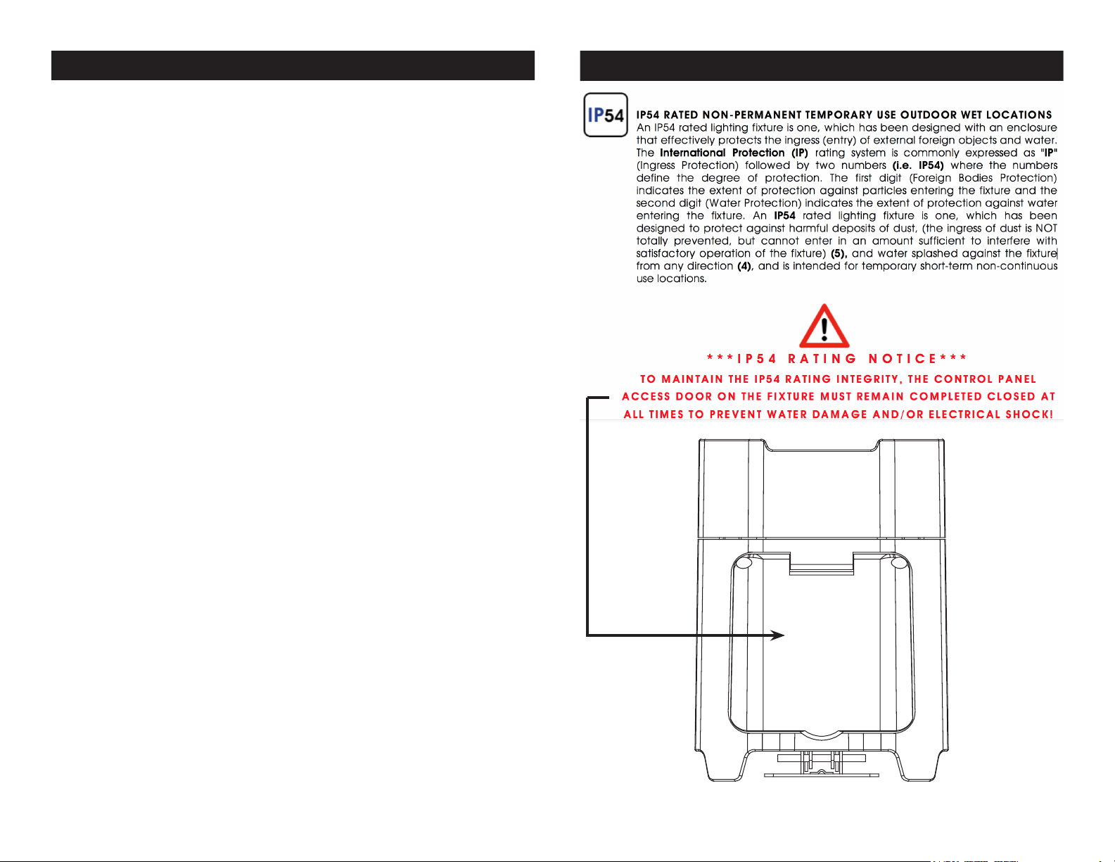
Element QAIP IP Notice
ADJ Products, LLC - www.adj.com - Element QAIP User Manual Page 4
ADJ Products, LLC - www.adj.com - Element QAIP User Manual Page 5
Page 4

Element QAIP Battery Precautions
Element QAIP Battery Precautions
1. Handling of Batteries
1.1 Do Not Short Circuit the Battery
Try to never short circuit the battery. It generates a very high
current which could cause the battery to overheat which may
result in electrolyte gel leakage, harmful fumes, or explosion.
The LIR tabs may easily short-circuit by placing them on conductive surface. A short circuit may lead to heat build up and
damage of the battery. An appropriate circuitry with PCM is
employed to protect accidental short circuit of the battery pack.
1.2 Mechanical shock
Droping the unit, impact hit, bending, etc. may cause failure or
shortend life of the LIR battery.
3. Other
3.1 Battery connection
1). Direct soldering of wire leads or devices to the battery is
strictly prohibited.
2). Lead tabs with pre-soldered wiring shall be spot welded to
the batteries. Direct soldering may cause damage of components, such as separator and insulator, by heat build up.
3.2 Prevention of short circuit within a battery pack
There is enough insulation layers between wiring and the batteries to provide extra safety protection. The battery pack is
constructed in a way that no short circuit will occur which may
cause smoke or re.
3.3 Do No Disassemble the Batteries
1). Never disassemble the batteries.
Doing this may cause a internal short circuit in the battery,
which may lead to harmful fumes, re, explosion, or other problems.
2). Electrolyte Gel is harmful
Electrolyte Gel should not leak from the LIR battery. Should the
electrolyte gel come into contact with the skin or eyes, ush the
area of contact immediately with fresh water and seek medical
attention immediately.
3.4 Do Not Expose the Battery to Heat or Fire
Never incinerate or dispose of the batteries in re. This may
cause an explosion, which would be very dangerous.
3.5 Do Not Expose the Battery to water or liquids
Never soak/drop the batteries in liquids such as water, seawa-
ter, drinks such as soft drinks, juices, coee or other.
3.6 Battery Replacement
For battery replacement please contact ADJ customer support
(800) 322-6337.
3.7 Do Not use a damaged Battery
The battery could be damaged during shipping, caused by
shock. Should the battery be found damaged, including damages to the plastic casing of the battery, deformation of the
battery package, smelling of an electrolyte, or leakage of the
electrolyte gel, or other, DO NOT use the battery. A battery with
a odor of electrolyte or a gel leakage should be placed away
from re to avoid re or explosion.
4. Battery Storage
When storing the battery, it should be stored at room temperature, with a charge of at least 50%. We recommend that during
long periods of storage that the battery be charged every 6
months. Doing this will prolong the life of the battery and will
also make sure that the battery charge does not fall below the
30% mark.
5. Other Chemical Reaction
Because batteries utilize a chemical reaction, battery performance will deteriorate over time even if stored for a long
period of time without being used. In addition, if the various
usage conditions such as charge, discharge, ambient tempera-
ture, etc. are not maintained within the specied ranges, the
ADJ Products, LLC - www.adj.com - Element QAIP User Manual Page 6
ADJ Products, LLC - www.adj.com - Element QAIP User Manual Page 7
Page 5
Element QAIP Operating Instructions
life expectancy of the battery maybe shortened or the device
in which the battery is used may be damaged by electrolyte
gel leakage. If the batteries cannot maintain a charge for long
periods of time, even when they are charged correctly, this may
indicate it is time to change the battery.
6. Battery Disposal
Please dispose of battery according to local regulations.
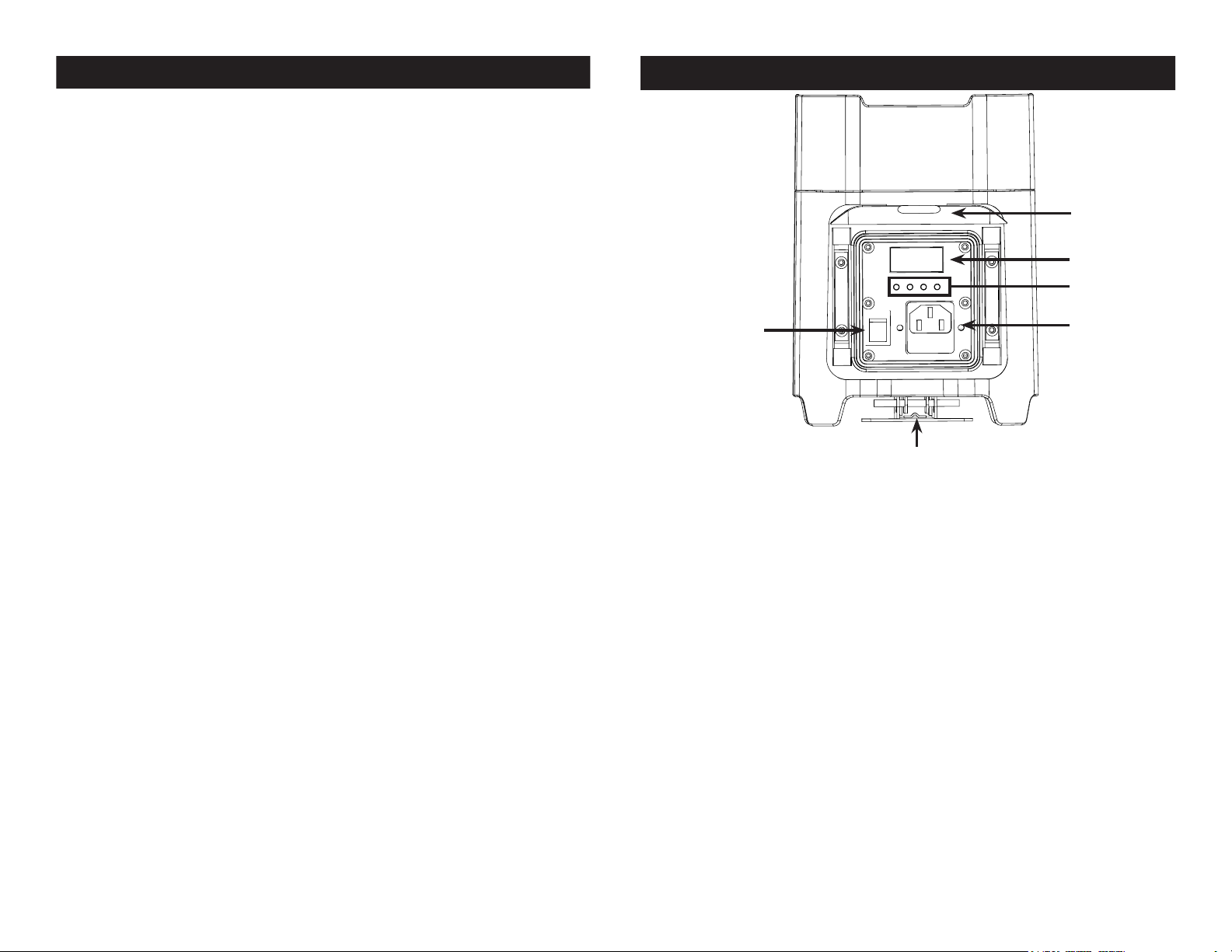
Element QAIP Layout Diagram
6
5
4
ADJ Products, LLC - www.adj.com - Element QAIP User Manual Page 8
1
2
3
1. Battery On/O Switch: This switch is used to activate the battery
power. You must also activate the LOAD function. See page
25 “Load Setting” to activate.
2. Kickstand: This kickstand is used to angle the unit to various
degrees. There are 3 dierent degree levels. Note: Be very
cautious at the degree in which you angle the unit at, due to
the fact that it could fall over.
3. Power Input & Fuse Holder: This input is used to connect the
included I.E.C. power cord. After connecting the power
cord, plug the other end into a matching power source.
Located inside the power socket is the f use housin g. See
page 37 for fuse replacement.
4. Mode Button: This button lets you scroll through the system menu.
Setup Button: This button lets you Enter submenu’s.
Up & Down Button: These button’s are used to scroll through
submenu’s and make adjustments in the submenu’s
5. Digital Display: This will display the various menu’s, submenu’s,
and adjustments.
6. Control Panel Access Door: Lifting this door will allow you to
access the controls and functions.
ADJ Products, LLC - www.adj.com - Element QAIP User Manual Page 9
Page 6
Element QAIP Set Up
Power Supply: The ADJ Element QAIP contains an automatic volt-
age switch, which will auto sense the voltage when it is plugged into
the power source. With this switch there is no need to worry about the
correct power voltage, this unit can be plugged in anywhere.
Element QAIP DMX Control
DMX Mode:
Operating through a DMX controller gives the user the freedom to
create their own programs tailored to their own individual needs. To
control this unit in DMX mode, your controller must be connected
to a Wifly TranCeiver. This is a Wifly unit only. The Element QAIP
has 5 DMX modes: 4 channel mode, 5 channel mode, 6 channel
mode, 9 channel mode, and 10 channel mode. See page’s 11-22 for
each mode’s DMX traits.
1. This function will allow you to control each individual fixture’s
traits with a standard DMX 512 controller.
2. To run your fixture in DMX mode press the MODE button until
“d.XXX” is displayed. “XXX” represents the current displayed DMX
address. Use the UP or DOWN buttons to select your desired
DMX address, then press the SETUP button to select your DMX
Channel mode.
3. Use the UP or DOWN buttons to scroll through the DMX Channel
modes. The Channel modes are listed below:
• To run the 4 Channel Mode, press the MODE button until “Ch04”
is displayed. This is the 4 Channel DMX Mode.
• To run the 5 Channel Mode, press the MODE button until “Ch05”
is displayed. This is the 5 Channel DMX Mode.
• To run the 6 Channel Mode, press the MODE button until “Ch06”
is displayed. This is the 6 Channel DMX Mode.
• To run the 9 Channel Mode, press the MODE button until “Ch09”
is displayed. This is the 9 Channel DMX Mode.
• To run the 10 Channel Mode, press the MODE button until
“Ch010” is displayed. This is the 10 Channel DMX Mode.
4. Please see pages 11-22 for DMX values and traits.
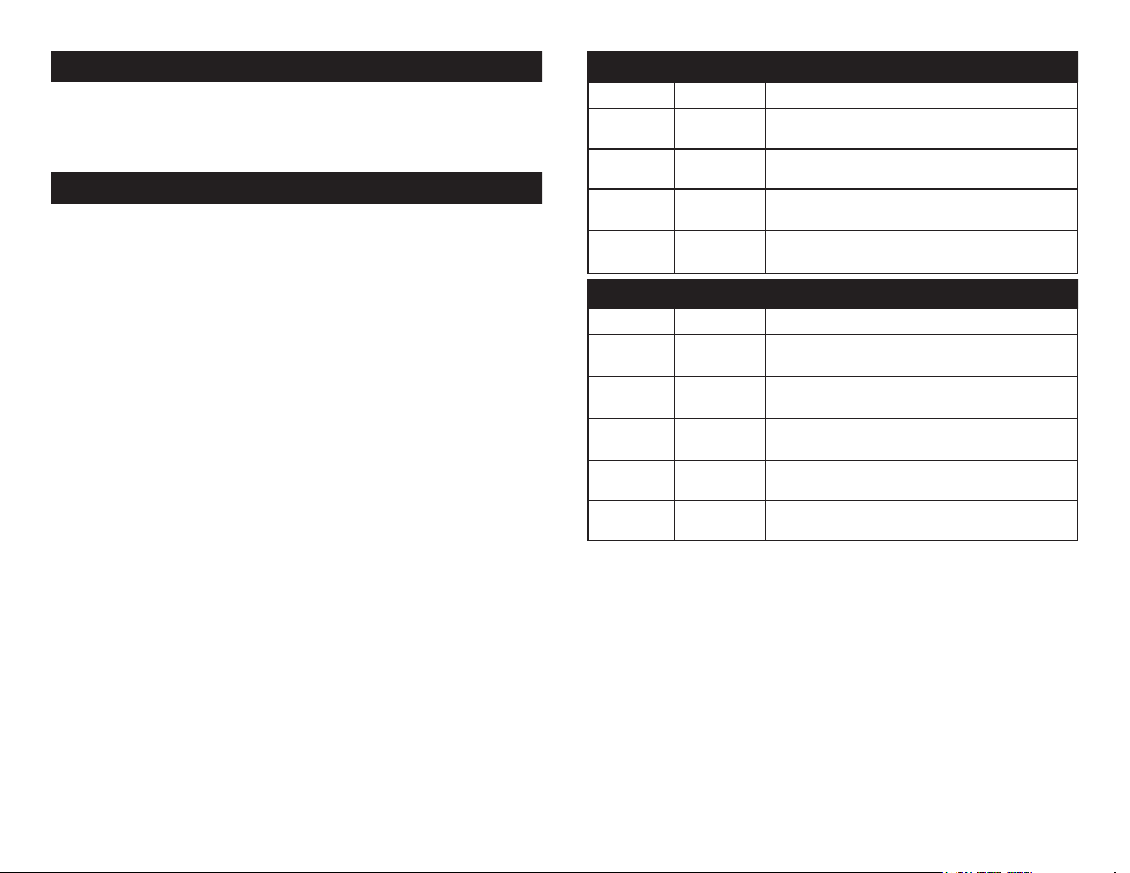
Element QAIP 4 Channel Mode
Channel Value Function
1 RED
0 - 255 0% - 100%
2 GREEN
0 - 255 0% - 100%
3 BLUE
0 - 255 0% - 100%
4 AMBER
0 - 255 0% - 100%
Element QAIP 5 Channel Mode
Channel Value Function
1 RED
0 - 255 0% - 100%
2 GREEN
0 - 255 0% - 100%
3 BLUE
0 - 255 0% - 100%
4 AMBER
0 - 255 0% - 100%
5 MASTER DIMMER
0 - 255 0% - 100%
ADJ Products, LLC - www.adj.com - Element QAIP User Manual Page 11ADJ Products, LLC - www.adj.com - Element QAIP User Manual Page 10
Page 7
Element QAIP 6 Channel Mode
Element QAIP 9 Channel Mode
Channel Value Function
1 RED
0 - 255 0% - 100%
2 GREEN
0 - 255 0% - 100%
3 BLUE
0 - 255 0% - 100%
4 AMBER
0 - 255 0% - 100%
5 STROBING
0 - 31 LED OFF
32 - 63 LED ON
64 - 95 STROBING SLOW - FAST
96 - 127 LED ON
128 - 159 PULSE STROBING SLOW - FAST
160 - 191 LED ON
192 - 223 RANDOM STROBING SLOW - FAST
224 - 255 LED ON
6 MASTER DIMMER
0 - 255 0% - 100%
7 PROGRAM SELECTION MODE
0 - 51 DIMMING MODE
52 - 102 COLOR MACRO MODE
103 - 153 COLOR CHANGE MODE
154 - 204 COLOR FADE MODE
205 - 255 SOUND ACTIVE MODE
ADJ Products, LLC - www.adj.com - Element QAIP User Manual Page 13ADJ Products, LLC - www.adj.com - Element QAIP User Manual Page 12
Page 8

Element QAIP 9 Channel Mode
Channel Value Function
Element QAIP 9 Channel Mode
Channel Value Function
8 COLOR MACROS/COLOR CHANGE/
COLOR FADE/SOUND ACTIVITY
0 - 255 COLOR MACRO MODE
See the Color Macro Chart pages 23-24
COLOR CHANGE PROGRAMS
0 - 15 COLOR CHANGE 1
16 - 31 COLOR CHANGE 2
32 - 47 COLOR CHANGE 3
48 - 63 COLOR CHANGE 4
64 - 79 COLOR CHANGE 5
80 - 95 COLOR CHANGE 6
96 - 111 COLOR CHANGE 7
112 - 127 COLOR CHANGE 8
128 - 143 COLOR CHANGE 9
144 - 159 COLOR CHANGE 10
160 - 175 COLOR CHANGE 11
176 - 191 COLOR CHANGE 12
192 - 207 COLOR CHANGE 13
208 - 223 COLOR CHANGE 14
224 - 239 COLOR CHANGE 15
240 - 255 COLOR CHANGE 16
When Channel 7 is between the values of 0-51, Channels 1-4 are used,
and Channel 5 will control strobing.
When Channel 7 is between the values of 52-102, Channel 8 is in Color
Macros Mode, and Channel 5 will control strobing.
8 COLOR MACROS/PROGRAMS/
SOUND ACTIVITIY
COLOR FADE PROGRAMS
0 - 15 COLOR FADE 1
16 - 31 COLOR FADE 2
32 - 47 COLOR FADE 3
48 - 63 COLOR FADE 4
64 - 79 COLOR FADE 5
80 - 95 COLOR FADE 6
96 - 111 COLOR FADE 7
112 - 127 COLOR FADE 8
128 - 143 COLOR FADE 9
144 - 159 COLOR FADE 10
160 - 175 COLOR FADE 11
176 - 191 COLOR FADE 12
192 - 207 COLOR FADE 13
208 - 223 COLOR FADE 14
224 - 239 COLOR FADE 15
240 - 255 COLOR FADE 16
When Channel 7 is between the values of 103-153, Channel 8 is in Color
Change Mode, and Channel 9 will control the color change speed.
When Channel 7 is between the values of 154-204, Channel 8 is in Color
Fade Mode, and Channel 9 will control the color fade speed.
When Channel 7 is between the values of 205-255, Channel 8 is in Sound
Active Mode, and Channel 9 will control the sound sensitivity.
ADJ Products, LLC - www.adj.com - Element QAIP User Manual Page 15ADJ Products, LLC - www.adj.com - Element QAIP User Manual Page 14
Page 9

Element QAIP 9 Channel Mode
Channel Value Function
Element QAIP 9 Channel Mode
Channel Value Function
8 COLOR MACROS/PROGRAMS/
SOUND ACTIVITY
SOUND ACTIVE PROGRAMS
0 - 15 SOUND ACTIVE MODE 1
16 - 31 SOUND ACTIVE MODE 2
32 - 47 SOUND ACTIVE MODE 3
48 - 63 SOUND ACTIVE MODE 4
64 - 79 SOUND ACTIVE MODE 5
80 - 95 SOUND ACTIVE MODE 6
96 - 111 SOUND ACTIVE MODE 7
112 - 127 SOUND ACTIVE MODE 8
128 - 143 SOUND ACTIVE MODE 9
144 - 159 SOUND ACTIVE MODE 10
160 - 175 SOUND ACTIVE MODE 11
176 - 191 SOUND ACTIVE MODE 12
192 - 207 SOUND ACTIVE MODE 13
208 - 223 SOUND ACTIVE MODE 14
224 - 239 SOUND ACTIVE MODE 15
240 - 255 SOUND ACTIVE MODE 16
9 PROGRAM SPEED/SOUND SENSITIVE
0 - 255 SLOW - FAST
0 - 255 LEAST SENSITIVE - MOST SENSITIVE
When Channel 7 is between the values of 0-51, Channels 1-4 are used,
and Channel 5 will control strobing.
When Channel 7 is between the values of 52-102, Channel 8 is in Color
Macros Mode, and Channel 5 will control strobing.
When Channel 7 is between the values of 103-153, Channel 8 is in Color
Change Mode, and Channel 9 will control the color change speed.
When Channel 7 is between the values of 154-204, Channel 8 is in Color
Fade Mode, and Channel 9 will control the color fade speed.
When Channel 7 is between the values of 205-255, Channel 8 is in Sound
Active Mode, and Channel 9 will control the sound sensitivity.
8 0 - 15 COLOR FADE 1
16 - 31 COLOR FADE 2
32 - 47 COLOR FADE 3
48 - 63 COLOR FADE 4
64 - 79 COLOR FADE 5
80 - 95 COLOR FADE 6
96 - 111 COLOR FADE 7
112 - 127 COLOR FADE 8
128 - 143 COLOR FADE 9
144 - 159 COLOR FADE 10
160 - 175 COLOR FADE 11
176 - 191 COLOR FADE 12
192 - 207 COLOR FADE 13
208 - 223 COLOR FADE 14
224 - 239 COLOR FADE 15
240 - 255 COLOR FADE 16
SOUND ACTIVE PROGRAMS
0 - 15 SOUND ACTIVE MODE 1
16 - 31 SOUND ACTIVE MODE 2
32 - 47 SOUND ACTIVE MODE 3
48 - 63 SOUND ACTIVE MODE 4
64 - 79 SOUND ACTIVE MODE 5
80 - 95 SOUND ACTIVE MODE 6
96 - 111 SOUND ACTIVE MODE 7
112 - 127 SOUND ACTIVE MODE 8
128 - 143 SOUND ACTIVE MODE 9
144 - 159 SOUND ACTIVE MODE 10
160 - 175 SOUND ACTIVE MODE 11
176 - 191 SOUND ACTIVE MODE 12
192 - 207 SOUND ACTIVE MODE 13
208 - 223 SOUND ACTIVE MODE 14
224 - 239 SOUND ACTIVE MODE 15
240 - 255 SOUND ACTIVE MODE 16
ADJ Products, LLC - www.adj.com - Element QAIP User Manual Page 17ADJ Products, LLC - www.adj.com - Element QAIP User Manual Page 16
Page 10

Element QAIP 9 Channel Mode
Channel Value Function
Element QAIP 10 Channel Mode
Channel Value Function
9 PROGRAM SPEED/SOUND SENSITIVE
0 - 255 SLOW - FAST
0 - 255 LEAST SENSITIVE - MOST SENSITIVE
When Channel 7 is between the values of 0-51, Channels 1-4 are used,
and Channel 5 will control strobing.
When Channel 7 is between the values of 52-102, Channel 8 is in Color
Macros Mode, and Channel 5 will control strobing.
When Channel 7 is between the values of 103-153, Channel 8 is in Color
Change Mode, and Channel 9 will control the color change speed.
When Channel 7 is between the values of 154-204, Channel 8 is in Color
Fade Mode, and Channel 9 will control the color fade speed.
When Channel 7 is between the values of 205-255, Channel 8 is in Sound
Active Mode, and Channel 9 will control the sound sensitivity.
1 RED
0 - 255 0% - 100%
2 GREEN
0 - 255 0% - 100%
3 BLUE
0 - 255 0% - 100%
4 AMBER
0 - 255 0% - 100%
5 STROBING
0 - 31 LED OFF
32 - 63 LED ON
64 - 95 STROBING SLOW - FAST
96 - 127 LED ON
128 - 159 PULSE STROBING SLOW - FAST
160 - 191 LED ON
192 - 223 RANDOM STROBING SLOW - FAST
224 - 255 LED ON
6 MASTER DIMMER
0 - 255 0% - 100%
7 PROGRAM SELECTION MODE
0 - 51 DIMMING MODE
52 - 102 COLOR MACRO MODE
103 - 153 COLOR CHANGE MODE
154 - 204 COLOR FADE MODE
205 - 255 SOUND ACTIVE MODE
ADJ Products, LLC - www.adj.com - Element QAIP User Manual Page 18
ADJ Products, LLC - www.adj.com - Element QAIP User Manual Page 19
Page 11

Element QAIP 10 Channel Mode
Element QAIP 10 Channel Mode
Channel Value Function
8 COLOR MACROS/COLOR CHANGE/
COLOR FADE/SOUND ACTIVITY
0 - 255 COLOR MACRO MODE
See the Color Macro Chart pages 23-24
COLOR CHANGE PROGRAMS
0 - 15 COLOR CHANGE 1
16 - 31 COLOR CHANGE 2
32 - 47 COLOR CHANGE 3
48 - 63 COLOR CHANGE 4
64 - 79 COLOR CHANGE 5
80 - 95 COLOR CHANGE 6
96 - 111 COLOR CHANGE 7
112 - 127 COLOR CHANGE 8
128 - 143 COLOR CHANGE 9
144 - 159 COLOR CHANGE 10
160 - 175 COLOR CHANGE 11
176 - 191 COLOR CHANGE 12
192 - 207 COLOR CHANGE 13
208 - 223 COLOR CHANGE 14
224 - 239 COLOR CHANGE 15
240 - 255 COLOR CHANGE 16
When Channel 7 is between the values of 0-51, Channels 1-4 are used,
and Channel 5 will control strobing.
When Channel 7 is between the values of 52-102, Channel 8 is in Color
Macros Mode, and Channel 5 will control strobing.
When Channel 7 is between the values of 103-153, Channel 8 is in Color
Change Mode, and Channel 9 will control the color change speed.
When Channel 7 is between the values of 154-204, Channel 8 is in Color
Fade Mode, and Channel 9 will control the color fade speed.
When Channel 7 is between the values of 205-255, Channel 8 is in Sound
Active Mode, and Channel 9 will control the sound sensitivity.
Channel Value Function
8 0 - 15 COLOR FADE 1
16 - 31 COLOR FADE 2
32 - 47 COLOR FADE 3
48 - 63 COLOR FADE 4
64 - 79 COLOR FADE 5
80 - 95 COLOR FADE 6
96 - 111 COLOR FADE 7
112 - 127 COLOR FADE 8
128 - 143 COLOR FADE 9
144 - 159 COLOR FADE 10
160 - 175 COLOR FADE 11
176 - 191 COLOR FADE 12
192 - 207 COLOR FADE 13
208 - 223 COLOR FADE 14
224 - 239 COLOR FADE 15
240 - 255 COLOR FADE 16
SOUND ACTIVE PROGRAMS
0 - 15 SOUND ACTIVE MODE 1
16 - 31 SOUND ACTIVE MODE 2
32 - 47 SOUND ACTIVE MODE 3
48 - 63 SOUND ACTIVE MODE 4
64 - 79 SOUND ACTIVE MODE 5
80 - 95 SOUND ACTIVE MODE 6
96 - 111 SOUND ACTIVE MODE 7
112 - 127 SOUND ACTIVE MODE 8
128 - 143 SOUND ACTIVE MODE 9
144 - 159 SOUND ACTIVE MODE 10
160 - 175 SOUND ACTIVE MODE 11
176 - 191 SOUND ACTIVE MODE 12
192 - 207 SOUND ACTIVE MODE 13
208 - 223 SOUND ACTIVE MODE 14
224 - 239 SOUND ACTIVE MODE 15
240 - 255 SOUND ACTIVE MODE 16
ADJ Products, LLC - www.adj.com - Element QAIP User Manual Page 21ADJ Products, LLC - www.adj.com - Element QAIP User Manual Page 20
Page 12

Element QAIP 10 Channel Mode
Color No. DMX
VAULE
RGBA COLOR INTENSITY
RED GREEN BLUE AMBER
Color33 129-132 255 206 143 0
Color34 133-136 254 177 153 0
Color35 137-140 254 192 138 0
Color36 141-144 254 165 98 0
Color37 145-148 254 121 0 0
Color38 149-152 176 17 0 0
Color39 153-156 96 0 11 0
Color40 157-160 234 139 171 0
Color41 161-164 224 5 97 0
Color42 165-168 175 77 173 0
Color43 169-172 119 130 199 0
Color44 173-176 147 164 212 0
Color45 177-180 88 2 163 0
Color46 181-184 0 38 86 0
Color47 185-188 0 142 208 0
Color48 189-192 52 148 209 0
Color49 193-196 1 134 201 0
Color50 197-200 0 145 212 0
Color51 201-204 0 121 192 0
Color52 205-208 0 129 184 0
Color53 209-212 0 83 115 0
Color54 213-216 0 97 166 0
Color55 217-220 1 100 167 0
Color56 221-224 0 40 86 0
Color57 225-228 209 219 182 0
Color58 229-232 42 165 85 0
Color59 233-236 0 46 35 0
Color60 237-240 8 107 222 0
Color61 241-244 0
Color62 245-248 0
Color63 249-252 0 0 0
Color64 253-255
0 255 0 0
255
0 255 0
0 0 255
Channel Value Function
Element QAIP Color Macro Chart
9 PROGRAM SPEED/SOUND SENSITIVE
0 - 255 SLOW - FAST
0 - 255 LEAST SENSITIVE - MOST SENSITIVE
10 DIMMER CURVES
0 - 20 STANDARD
21 - 40 STAGE
41 - 60 TV
61 - 80 ARCHITECTURAL
81 - 100 THEATRE
101 - 255 DEFAULT TO UNIT SETTING
When Channel 7 is between the values of 0-51, Channels 1-4 are used,
and Channel 5 will control strobing.
When Channel 7 is between the values of 52-102, Channel 8 is in Color
Macros Mode, and Channel 5 will control strobing.
When Channel 7 is between the values of 103-153, Channel 8 is in Color
Change Mode, and Channel 9 will control the color change speed.
When Channel 7 is between the values of 154-204, Channel 8 is in Color
Fade Mode, and Channel 9 will control the color fade speed.
When Channel 7 is between the values of 205-255, Channel 8 is in Sound
Active Mode, and Channel 9 will control the sound sensitivity.
Color No. DMX
VAULE
OFF 0 0 0 0 0
Color1 1-4 80 255 234 80
Color2 5-8 80 255 164 80
Color3 9-12 77 255 112 77
Color4 13-16 117 255 83 83
Color5 17-20 160 255 77 77
Color6 21-24 223 255 83 83
Color7 25-28 255 243 77 77
Color8 29-32 255 200 74 74
Color9 33-36 255 166 77 77
Color10 37-40 255 125 74 74
Color11 41-44 255 97 77 74
Color12 45-48 255 71 77 71
Color13 49-52 255 83 134 83
Color14 53-56 255 93 182 93
Color15 57-60 255 96 236 96
Color16 61-64 238 93 255 93
Color17 65-68 196 87 255 87
Color18 69-72 150 90 255 90
Color19 73-76 100 77 255 77
Color20 77-80 77 100 255 77
Color21 81-84 67 148 255 67
Color22 85-88 77 195 255 77
Color23 89-92 77 234 255 77
Color24 93-96 158 255 144 144
Color25 97-100 255 251 153 153
Color26 101-104 255 175 147 147
Color27 105-108 255 138 186 138
Color28 109-112 255 147 251 147
Color29 113-116 151 138 255 138
Color30 117-120
Color31 121-124 138 169 255 138
Color32 125-128 255 255 255 255
ADJ Products, LLC - www.adj.com - Element QAIP User Manual Page 23ADJ Products, LLC - www.adj.com - Element QAIP User Manual Page 22
RED GREEN BLUE AMBER
99 0 255 100
RGBA COLOR INTENSITY
Page 13

Element QAIP Color Macro Chart
71°
63°
Element QAIP Operating Instructions
LCD Display Lock:
The display will lock after 30 seconds. Press and hold the MODE button for at least 10 seconds to unlock the display.
Operating Power:
There are two ways to supply power to this unit; battery power or AC
power.
• AC Power - To run the unit using AC power, plug the unit into a
power source, and activate the Load setting. When using AC power
make sure the Battery Switch is in the OFF position.
• Battery Power - To run the unit using Battery power, switch the
battery switch located on the bottom of the fixture into the “On” postion, and activate the Load setting.
Load Setting
You need to activate this function regardless of Battery power or AC
power. This function activates the LED PCB output
1. To activate Load, press the MODE button until either “bXXX”,
“bsXX”, or “LoXX” is displayed. “XX” is the represents the current
setting of those menus.
2. Press the SET UP button so that “LoXX” is displayed. “XX”
represents either “oN” or “oF” (Off).
3. Press the UP or DOWN buttons so that “oN” is displayed.
Energy Saving Mode
This will decrease the LED’s brightness gradually when the battery
life is less than 80%, this is will extend the battery life.
1. To activate energy saving mode, press the MODE button until
either “bXXX”, “bsXX”, or “LoXX” is displayed. “XX” is the repre-
sents the current setting of those menus.
2. Press the SET UP button so that “bS:XX” is displayed. “XX”
represents either “ON” or “OFF”.
3. Press the UP or DOWN button so that “ON” is displayed. If “ON”
is displayed already then the fixture is already in energy saving
mode.
ADJ Products, LLC - www.adj.com - Element QAIP User Manual Page 24 ADJ Products, LLC - www.adj.com - Element QAIP User Manual Page 25
Page 14

Element QAIP Operating Instructions
Element QAIP Operating Instructions
LED Display On/Off:
To set the LED display light to turn off after 20 seconds, press the
MODE button until “dXX” is displayed. “XX” represents either ON or
OFF. Press the UP or DOWN buttons so that OFF is displayed. Now
the display light will turn off after 30s. Press any button to turn the
display on again.
Operating Modes:
The Element QAIP has five operating modes:
• RGBA Dimmer Mode - Choose one of the four colors to remain
static or adjust the intensity of each color to make your desired
color.
• Sound-Active mode - The unit will react to sound, chasing through
the built in programs. There are 16 sound active modes.
• Auto Run Mode - In Auto Run mode, you can choose 1 of 16
color change modes, 1 of 16 color fade modes, or a combo color
change & fade mode.
• Static Color Mode - There are 63 colors to choose from.
• DMX control mode - This function will allow you to control each
individual fixtures traits with a standard DMX 512 controller.
Sound Active Mode:
1. Plug the fixture in and press the MODE button until “SoXX” is dis played. “XX” represents the current sound active mode (1-16).
2. Use the UP or DOWN buttons to find your desired sound active
mode.
3. Press the SET UP button to enter sound sensitivity adjustment.
“SJ-X” will be displayed. Use the UP or DOWN buttons to adjust
the sensitivity. “SJ-1” is the lowest sensitivity, “SJ-8” is the high est. “SJ-0” turns the sound sensitivity off.
RGBA Dimmer Mode:
1. Plug the fixture in and press the MODE button “r: XXX” is dis-
played. You now are in Red dimming mode. Press the UP and
DOWN buttons to adjust intensity. After you have finished adjust-
ing the intensity, or if you would like to skip to the next color,
press the SET UP button.
2. When “G: XXX” is displayed you are in Green dimming mode.
Press the UP and DOWN buttons to adjust intensity.
3. When “b: XXX” is displayed you are in Blue dimming mode.
Press the UP and DOWN buttons to adjust intensity.
4. When “A: XXX” (Amber) is displayed you are in Amber dimming
mode. Press the UP and DOWN buttons to adjust intensity.
5. After you have adjusted the colors to make your desired color
you can then activate strobing by pressing the SET UP button to
enter the strobe mode.
6. “FS: XX” will be displayed, this is strobe mode. The strobe
can be adjusted between “00” (flash off) to “15” (fastest flash).
Static Color Mode:
1. Plug the fixture in and press the MODE button until “CLXX” is dis-
played.
2. There are 63 colors to choose from. Select your desired color by
pressing the UP and DOWN buttons. After you have selected your
desired color you can activate strobing by pressing the SET UP
button to enter the Flash (strobe) mode.
3. “FS.XX” will be displayed, this is Flash mode. The Flash can be
adjusted between “FS.00” (flash off) to “FS.15” (fastest flash).
ADJ Products, LLC - www.adj.com - Element QAIP User Manual Page 27ADJ Products, LLC - www.adj.com - Element QAIP User Manual Page 26
Page 15

Element QAIP Operating Instructions
Element QAIP Operating Instructions
Auto Run Mode:
There are 3 types of Auto Run Modes to choose from; Color Fade,
Color Change, and both modes running together.
is adjustable in all 3 modes.
1. Plug the fixture in and press the MODE button until either “AFXX”,
“AJXX”, or “A-JF” is displayed.
• AFXX = Color Fade mode, there are 16 Color Fade modes to
choose from. Use the UP or DOWN buttons to scroll through the
different Auto Fade modes.
• AJXX = Color Change mode, there are 16 Color Change modes to
choose from. Use the UP or DOWN buttons to scroll through the
different Auto Change modes.
• A-JF = Both Color Fade and Color Change modes running.
2. After you have chosen your desired running mode press the SET
UP button until “SP.XX” is displayed. When this is displayed you
can adjust the running speed of your desired program. Use the
UP or DOWN button to adjust the speed between “SP.01” (slow-
est) and “SP.16” (fastest). Once you have set your desired running
speed, press the SET UP button to return to your desired Auto
Run Mode.
The running speed
DMX Mode:
Operating through a DMX controller gives the user the freedom to
create their own programs tailored to their own individual needs. To
control this unit in DMX mode, your controller must be connected
to a Wifly TranCeiver. This is a Wifly unit only. The Element QAIP
has 5 DMX modes: 4 channel mode, 5 channel mode, 6 channel
mode, 9 channel mode, and 10 channel mode. See page’s 11-22 for
each mode’s DMX traits.
1. This function will allow you to control each individual fixture’s
traits with a standard DMX 512 controller.
2. To run your fixture in DMX mode press the MODE button until
“d.XXX” is displayed. “XXX” represents the current displayed DMX
address. Use the UP or DOWN buttons to select your desired
DMX address, then press the SETUP button to select your DMX
Channel mode.
3. Use the UP or DOWN buttons to scroll through the DMX Channel
modes. The Channel modes are listed below:
• To run the 4 Channel Mode, press the MODE button until “Ch04”
is displayed. This is the 4 Channel DMX Mode.
• To run the 5 Channel Mode, press the MODE button until “Ch05”
is displayed. This is the 5 Channel DMX Mode.
• To run the 6 Channel Mode, press the MODE button until “Ch06”
is displayed. This is the 6 Channel DMX Mode.
• To run the 9 Channel Mode, press the MODE button until “Ch09”
is displayed. This is the 9 Channel DMX Mode.
• To run the 10 Channel Mode, press the MODE button until
“Ch010” is displayed. This is the 10 Channel DMX Mode.
4. Please see pages 11-22 for DMX values and traits.
ADJ Products, LLC - www.adj.com - Element QAIP User Manual Page 28
ADJ Products, LLC - www.adj.com - Element QAIP User Manual Page 29
Page 16

Element QAIP Operating Instructions Element QAIP Operating Instructions
DMX State:
This mode can be used as a precaution mode, that in case the DMX
signal is lost, the operating mode chosen in the setup is the running
mode the xture will go into when the DMX signal is lost. You can also
set this as the operating mode you would like the unit to return to when
power is applied.
1. Plug the fixture in and press the MODE button until “d.XXX” is dis-
played. “XXX” represents the current displayed DMX address.
2. Press the SET UP button so that “nodn” is displayed. Use the UP
and DOWN buttons to scroll through the DMX states.
• “bLAC” (Blackout) - If the DMX signal is lost or interrupted,
the unit will automatically go into stand by mode.
• “LASt” (Last State) - If the DMX signal is lost or interrupted,
the xture will stay in the last DMX set up. If power is applied and
this mode is set, the unit will automatically go into the last DMX set
up.
• “ProG” (Auto Run) - If the DMX signal is lost or interrupted,
the unit will automatically go into Auto Run mode.
3. After you have found your desired setting, press SET UP to exit.
Dimmer Curve:
This is used to set the dimming curve used with DMX mode. See
page 36 for the dimming curves chart.
1. Plug the fixture in and press the MODE button until “d.XXX” is dis-
played. “XXX” represents the current displayed DMX address.
2. Press the SET UP button until “dr-X” is displayed. “X” represents
the displayed dimmer curve (0-4).
• 0 - Standard
• 1 - Stage
• 2 - TV
• 3 - Architectural
• 4 - Theatre
3. Press the UP or DOWN buttons to scroll through and select your
desired dimming curve.
WiFly On/Off and Wireless Addressing:
This function is used to activate the WiFly control and set the WiFly
address.
NOTE: The address must match the address that is set to WiFly
TransCeiver or WiFly controller.
1. Plug the fixture in and press the MODE button until “rCXX” is
displayed. You are in wireless set up mode.
2. Press the UP or DOWN buttons the UP or DOWN buttons to turn
the Wireless “On” or “Off”.
3. Press the SET UP button to enter the Wireless address menu. Use
the UP or DOWN buttons to select your desired Wireless address.
Activate IR Sensor:
This function is used to activate and deactivate the IR sensor. When
this function is activated you can control the fixture using the UC IR or
Airstream IR App. Please see page 34 for controls and functions.
1. Plug the fixture in and press the MODE button until “dXX” is dis-
played. “XX” represents either “on” or “oFF”.
2. Press the SET UP button until “IrXX” is displayed. “XX” represents
either “on” or “oF”.
3. Press the UP or DOWN buttons to either activate the remote func-
tion (On) or deactivate it (Off).
Slave Setting:
1. Plug the fixture in and press the MODE button until “SLAv” is
displayed. The unit now designate a “Slave” unit in a Master-Slave
set up.
Default Running Mode:
This is a default running mode. When this mode is activated all modes
will return to their default settings.
1. Plug the fixture in and press the MODE button until “dXX” is dis-
played. “XX” represents either “on” or “oFF”.
2. Press the SET UP button until “dEFA” is displayed.
3. Press the UP and DOWN buttons simultaneously. Press the
MODE button to exit.
ADJ Products, LLC - www.adj.com - Element QAIP User Manual Page 30 ADJ Products, LLC - www.adj.com - Element QAIP User Manual Page 31
Page 17

Element QAIP WiFly Set Up
Element QAIP
UC IR & Airstream App Control
This unit can only be controlled using WiFly. Your DMX controller must
be connected to a ADJ WiFly Transceiver to use this function. You are
able to communicate up to 2500 feet/760 meters (open line of sight).
1. Follow the instructions on page 31 to set the WiFly address and to
activate WiFly. The address must match the address set on the
WiFly WiFly Transceiver.
2. After you have set the WiFly address, follow the DMX instructions
on page 29 to select your desired DMX Channel mode and set
your DMX address.
3. Apply power to the ADJ WiFly Transceiver. The fixture must be set
up first before you apply power to WiFly Transceiver.
4. If everything is set up properly and the fixture is receiving a
Wireless signal, you should now be able to control it with a DMX
controller.
Element QAIP WiFly Master-Slave Set Up
Master-Slave Configuration:
This function will allows you to link units together to run in a MasterSlave setup. In a Master-Slave set up one unit will act as the controlling unit and the others will react to the controlling units built-in programs. Any unit can act as a Master or as a Slave however, only one
unit can be programmed to act as the “Master.”
1. Follow the instructions on page 31 to set the WiFly address and to
activate WiFly. The addresses on each fixture must be the same.
2. After you have set the WiFly address, select your “Master” unit
and set your desired operating mode.
3. For the “Slave” unit(s), put the unit in Slave mode. See page 31
SLAVE SETTING to set the unit as a Slave.
4. If everything is set up correctly, the “Slave” units will start follow-
ing the “Master” unit.
The UC IR (sold separately) infrared remote gives you control of
various functions (See below). To control the fixture you must aim the
remote at the front of the fixture and be no more than 30 feet away.
To use the ADJ UC IR you must first activate the fixtures infrared sensor, to activate the sensor please see the instructions on page 31.
The Airstream IR (sold separately) remote transmitter plugs into the
headphone jack of your iOS phone or tablet. To control your IR fixture
you must raise the volume to the maximum on your iOS phone or tablet and aim the transmitter at the fixture sensor and be no more than
15 feet away. After you have purchased the Airstream IR transmitters,
the app is a free download from the app store for your iOS phone
or tablet. The app comes with 3 pages of control depending on the
fixture you are using. Please see below for IR functions including the
corresponding app page.
Works with App page 1.
STAND BY - Pressing this button will blackout the fixture. Press the button
again to return to the initial state.
FULL ON - Press this button to fully light up the unit.
FADE/GOBO - This button activates color change mode, color fade mode
and color chang/fade mode. Each press of the button will cycle through the
modes.
“DIMMER +” and “DIMMER -” - Use these buttons to adjust the output intensity in color mode.
STROBE - Press this button to activate strobing. Use buttons 1-4 to adjust
the strobe speed. “1” being the slowest, “4” being the fastest.
COLOR - Press this button to activate color mode. Use buttons 1-9 to find
your desired color.
1-9 - Use buttons 1-9 to select your desired color in static color mode or
your desired color fade mode and color change mode. In color fade mode
and color change mode, press the Show 0 button to activate show 10. Press
the 1 button twice to activate show 11.
SOUND ON & OFF - Use the buttons to activate and deactivate sound active mode.
SHOW 0 - See buttons 1-9.
ADJ Products, LLC - www.adj.com - Element QAIP User Manual Page 32 ADJ Products, LLC - www.adj.com - Element QAIP User Manual Page 33
Page 18

Element QAIP Battery Status & Charging
DIMMER
Battery Status:
This function is used to check the life status of the battery.
Plug the fixture in and press the MODE button until “bXXX” is
displayed. “XXX” represents the current battery life. The number that is displayed is the remaining battery life. If “b---” is
displayed, it means that you are running the unit on AC power.
Please do not let the battery fully die, this severly shortens
the life of the battery.
NOTE: When the battery life is below 30% the battery percent-
age will flash. At 15% power the fixture will shut off.
NOTE: When using battery power, after 20 seconds of inactivity, the display will revert back to the battery life display.
Battery Recharge: To recharge the battery, plug the supplied
AC cord into the AC input on the side of the unit and plug the
other end into a matching power supply. It takes about 5 hours
to reach full charge (with the power o). The display will STOP
ashing when the unit reaches 100% charge.
Note: When unplugging the unit from charging and then
applying power via battery, there will be a minimal charge
drop.
For a faster recharge, turn the Load setting to “O” and turn the
battery “On”. See LOAD SETTING on page 25.
Element QAIP Dimmer Curve Chart
100%
50%
10%
0%
Rise Time Down Time
0 Sec
0 sec Fade Time 1 sec Fade Time
Dimming Curve
Ramp Effect
0 0
Rise Time (ms) Down Time (ms) Rise Time (ms) Down Time (ms)
Standard (default) 0 0 0 0
Stage 780 1100 1540 1660
TV 1180 1520 1860 1940
Architectural 1380 1730 2040 2120
Theatre 1580 1940 2230 2280
255 255
Time (ms)
Element QAIP Kickstand Angles
ADJ Products, LLC - www.adj.com - Element QAIP User Manual Page 34
82°
ADJ Products, LLC - www.adj.com - Element QAIP User Manual Page 35
71°
63°
Page 19

Element QAIP Dimensional Drawing
7.6”/194.44mm
6.6”/169.29mm
Element QAIP Fuse Replacement
Disconnect the unit from its power source. Remove the power cord
from the unit. Once the cord has been removed, you will find that the
fuse holder is located inside the power socket. Insert a flat-head screw
driver into the power socket and gently pry out the fuse holder. Remove
the bad fuse and replace with a new one. The fuse holder also has a
holder for a spare fuse.
Element QAIP Trouble Shooting
Listed below are a few common problems the user may encounter,
with solutions.
Unit not responding to DMX:
1. Check that the DMX cables are connected properly and are
wired correctly (pin 3 is “hot”; on some other DMX devices
pin 2 may be ‘hot’). Also, check that all cables are connected
to the right connectors; it does matter which way the inputs
and outputs are connected.
Element QAIP Cleaning
Due to fog residue, smoke, and dust cleaning the internal and external optical lenses must be carried out periodically to optimize light
output.
1. Use normal glass cleaner and a soft cloth to wipe down the
outside casing.
2. Clean the external optics with glass cleaner and a soft cloth
every 20 days.
3. Always be sure to dry all parts completely before plugging
the unit back in.
Cleaning frequency depends on the environment in which the fixture
operates (i.e. smoke, fog residue, dust, dew).
5.6”/144.52mm
5.6”/144.06mm
ADJ Products, LLC - www.adj.com - Element QAIP User Manual Page 36 ADJ Products, LLC - www.adj.com - Element QAIP User Manual Page 37
Page 20

Element QAIP Warranty
MANUFACTURER’S LIMITED WARRANTY
A. ADJ Products, LLC hereby warrants, to the original purchaser, ADJ Products, LLC products
to be free of manufacturing defects in material and workmanship for a prescribed period from
the date of purchase (see specific warranty period on reverse). This warranty shall be valid only if the
product is purchased within the United States of America, including possessions and
territories. It is the owner’s responsibility to establish the date and place of purchase by acceptable
evidence, at the time service is sought.
B. For warranty service you must obtain a Return Authorization number (RA#)
before sending back the product–please contact ADJ Products, LLC Service Department
at 800-322-6337. Send the product only to the ADJ Products, LLC factory. All
shipping charges must be pre-paid. If the requested repairs or service (including
parts replacement) are within the terms of this warranty, ADJ Products, LLC will pay return
shipping charges only to a designated point within the United States. If the entire instrument is
sent, it must be shipped in it’s original package. No accessories should be shipped with the product. If
any accessories are shipped with the product, ADJ Products, LLC shall have no liability whatsoever for
loss of or damage to any such accessories, nor for the safe return thereof.
C. This warranty is void if the serial number has been altered or removed; if the product is modified in any
manner which ADJ Products, LLC concludes, after inspection, affects the reliability of the product; if the
product has been repaired or serviced by anyone other than the ADJ Products, LLC factory unless prior
written authorization was issued to purchaser by ADJ Products, LLC; if the product is damaged because
not properly maintained as set forth in the instruction manual.
D. This is not a service contract, and this warranty does not include maintnance, cleaning or periodic check
up. During the period specified above, ADJ Products, LLC will replace defective parts at its expense
with new or refurbished parts, and will absorb all expenses for warranty service and repair labor by
reason of defects in material or workmanship. The sole responsibility of ADJ Products, LLC under this
warranty shall be limited to the repair of the product, or replacement thereof, including parts, at the sole
discretion of ADJ Products, LLC. All products covered by this warranty were manufactured after August
15, 2012, and bear indentifying marks to that effect.
E. ADJ Products, LLC reserves the right to make changes in design and/or improvements upon its products
without any obligation to include these changes in any products theretofore manufactured.
No warranty, whether expressed or implied, is given or made with respect to any accessory supplied with
products described above. Except to the extent prohibited by applicable law, all implied warranties made
by ADJ Products, LLC in connection with this product, including warranties of merchantability or fitness,
are limited in duration to the warranty period set forth above. And no warranties, whether expressed or
implied, including warranties of merchantability or fitness, shall apply to this product after said period
has expired. The consumer’s and/or Dealer’s sole remedy shall be such repair or replacement as is
expressly provided above; and under no circumstances shall ADJ Products, LLC be liable for any loss or
damage, direct or consequential, arising out of the use of, or inability to use, this product.
This warranty is the only written warranty applicable to ADJ Products, LLC Products and
supersedes all prior warranties and written descriptions of warranty terms and conditions heretofore
published.
MANUFACTURER’S LIMITED WARRANTY PERIODS:
•NonL.E.D.LightingProducts=1-year(365days)LimitedWarranty(Such as: Special Effect
Lighting, Intelligent Lighting, UV lighting, Strobes, Fog Machines, Bubble Machines, Mirror Balls, Par
Cans, Trussing, Lighting Stands etc. excluding LED and lamps)
•LaserProducts=1Year(365Days)LimitedWarranty(excluding laser diodes which have a 6 month
limited warranty)
•L.E.D.Products=2-year(730days)LimitedWarranty(excluding batteries which have a 180 day lim-
ited warranty). Note:2YearWarrantyonlyappliestopurchaseswithintheUnitedStates.
•StarTecSeries=1YearLimitedWarranty(excluding batteries which have a 180 day limited warranty).
•ADJDMXControllers=2Year(730Days)LimitedWarranty
Element QAIP Specifications
Model:
Element QAIP
Voltage: 100V ~ 240V/50~60Hz
LEDs: 6 x 5W RGBA (4-in-1) LEDs
Beam Angle: 40 Degrees
IP Rating: 54
Working Position: Any safe working position
Fuse: 250V, 2A
Power Draw: 46W
Weight: 6.5lbs./ 2.9Kgs.
Dimensions: 5.5” (L) x 5.5” (W) x 7.5” (H)
140 x 140 x 192mm
Colors: RGBA
DMX Channels: 5 DMX Modes: 4 Channel Mode
5 Channel Mode, 6 Channel Mode,
9 Channel Mode, & 10 Channel
Mode
Battery Charge Time: 5 Hours (With LOAD Off and POWER
On)
Battery Life: BATTERY SAVING MODE OFF
7.5 Hours (Full Charge Single Color)
2 Hours (Full On)
BATTERY SAVING MODE ON
21 Hours (Full Charge Single Color)
10 Hours (Full On)
Battery Lifetime*: Average Lifetime is 500 Charges
Battery Type: Fixed Lithium Battery
Battery Energy: 73.26WH (Watt Hours)
Battery Weight: 1 lb. / 0.42kg
Battery Voltage: 11.1V
Battery Capacity: 6.6AH
Total Lithium Ion Cells: 9pcs
Battery Wrap Material: PVC Sleeving + Highland Barley Paper
Warranty**: 2 Year (730 days) Limited Warranty
* This depends on charging frequency
**See Warranty page for more details
Please Note: Specications and improvements in the design of this unit and
this manual are subject to change without any prior written notice.
ADJ Products, LLC - www.adj.com - Element QAIP User Manual Page 38 ADJ Products, LLC - www.adj.com - Element QAIP User Manual Page 39
Page 21

Optional Accessories
ORDER CODE ITEM
EPC600 6-PACK SKB CASE
Element QAIP Notes Element QAIP
ADJ Products, LLC - www.adj.com - Element QAIP User Manual Page 40 ADJ Products, LLC - www.adj.com - Element QAIP User Manual Page 41
Page 22

Element QAIP Notes
ADJ Products, LLC - www.adj.com - Element QAIP User Manual Page 42
ADJ Products, LLC
6122 S. Eastern Ave. Los Angeles, CA 90040 USA
Tel: 323-582-2650 / Fax: 323-725-6100
Web: www.adj.com / E-mail: info@americandj.com
A.D.J. Supply Europe B.V.
Junostraat 2
6468 EW Kerkrade
The Netherlands
service@adjgroup.eu / www.adj.eu
Tel: +31 45 546 85 00 / Fax: +31 45 546 85 99
 Loading...