

Page 1
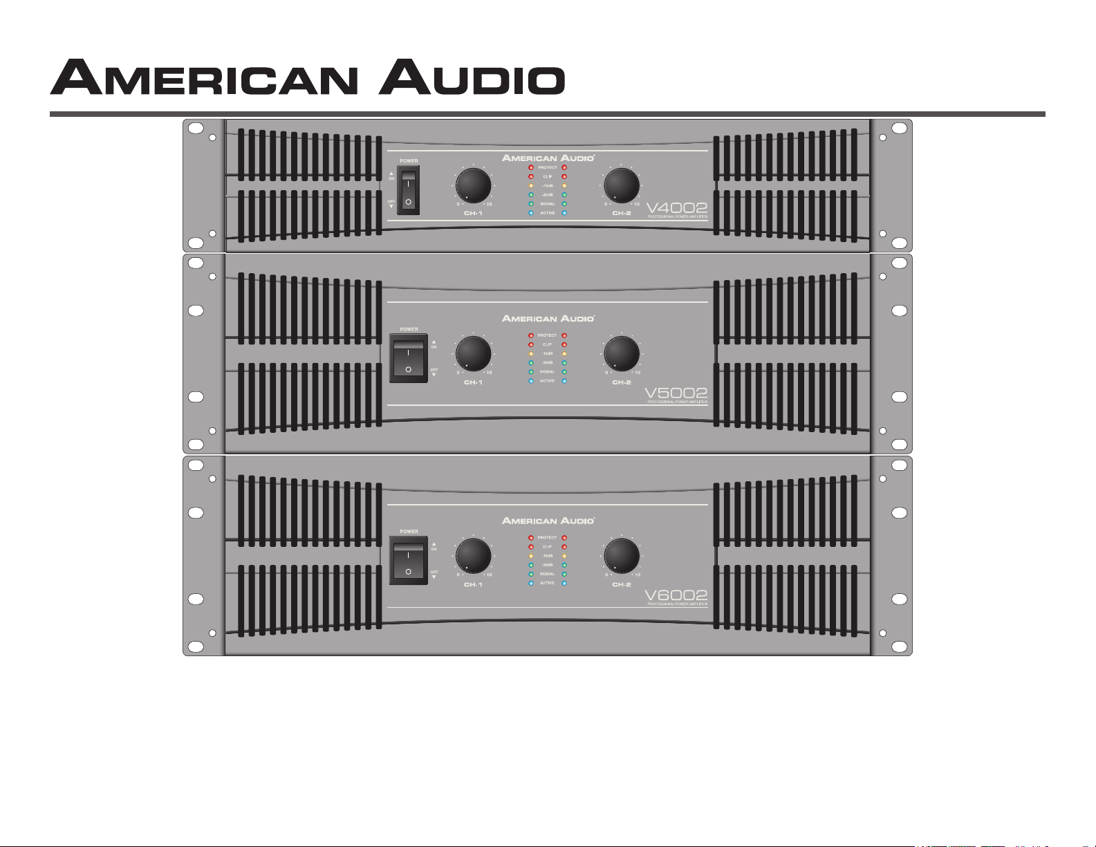
Professional Power Amplier
4/15
V4002,V5002, & V6002
User Instructions
Page 2
This symbol is intended to alert the user to the presence of non insulated "dangerous voltage" within the product's enclosure that may be of sucient magnitude to
constitute a risk of electric shock to persons.
This symbol is intended to alert the user of the presence of important operating and maintenance (servicing) instructions in the literature accompanying the product.
CAUTION: Risk of the electrical shock - DO NOT OPEN!
CAUTION: To reduce the risk of electrical shock, do not remove cover. No user serviceable parts inside. Refer all servicing to qualied service personnel.
WARNING: To prevent electrical shock or re hazard, do not expose this amplier to rain or moisture. Before using this amplier, read the user manual for further warnings.
Este símbolo tiene el propósito de alertar al usuario de la presencia de “voltaje peligroso“ que no tiene aislamiento dentro de la caja del producto que puede tener
una magnitud suciente como para constituir riesgo de corrientazo.
Este símbolo tiene el propósito de alertar al usuario de la presencia de instrucciones importantes sobre la operación y mantenimiento en la literatura que vienc con
el producto.
PRECAUCIÓN: Riesgo del choque eléctrico - NO SE ABRA
PRECAUCIÓN: Para disminuir el riesgo de choque eléctrico, no quite la cubierta. No hay piezas adentro que el usario puede reparar. Deje todo mantenimiento al los téc-
nicos cualicados.
ADVERTENCIA: Para prevenir choque eléctrico o riesgo de incendios, no deja expuesto a la lluvia o a la humedad este amplicador. Antes de usar este amplicador, lea
mas advertencias en la guia de operacion.
Ce symbole est utilisé pur indiquer à l’utilisateur la présence à l'intérieur de ce produit de tension non-isolée dangereuse pouvant être d'intensité susante pour
constituer un risque de choc électrique.
Ce symbole est utilisé pour indiquer à l’utilisateur qu'il trouvera d'importantes instructions importantes sur l'utilisation et l'entretien de l'appareil dans la littérature
accompagnant le produit.
ATTENTION: Risque de choc électrique - NE PAS OUVRIR!
ATTENTION: An de réduire le risque de choc électrique, ne pas enlever le couvercle. Il ne se trouve à l’intérieur aucune piéce pouvant être réparée par l'utilisateur. Coner
l'entretien à un personnel qualié.
AVERTISSEMENT: An de prévenir les risque de décharge ou de feu, n’exposez pas cet appareil à la pluie ou à l’humidité. Avant d’utiliser cet amplicateur, lisez les aver-
tissements supplémentaries situés dans le guide.
Dieses Symobl soll den Anwender vor unisollierten gefährlichen Spannungen innerhalb des Gehäuses warnen, die von Ausreichender Stärke sind, um einen elek-
trischen Schlag verursachen zu können.
Dieses Symobl soll den Benutzer auf wichtige Instruktionen in der Bedienungsanleitung aufmerksam machen, die Handhabung und Wartung des Produkts betref-
fen.
VORSICHT: Risiko - Elektrischer Schlag! Nicht önen!
VORSICHT: Um ddas Risiko eines elektrischen Schlages zu vermeiden, nicht die Abdeckung enfernen. Es benden sich keine Teile darin, die vom Anwender repariert
werden könnten. Reparaturen nur von qualizierte Fachpersonal durchführen lassen.
ACHTUNG: Um einen elektrischen Schlag oder Feuergefahr zu vermeiden, sollte diesen Gerät nicht dem Regen oder Feuchtigkeit ausgesetz werden. Vor Inbetriebnahme
unbedingt die Bedienungsanleitung lesen.
©American Audio® - www.americanaudio.us - V Series™ Power Amplifier User Manual Page 2
Page 3
CAUTION
Do not open -
risk of electric shock
CAUTION: TO REDUCE THE RISK OF ELECTRIC
SHOCK, DO NOT REMOVE THE COVER.
THERE ARE NO USER SERVICEABLE PARTS
INSIDE. REFER ALL SERVICE TO YOUR
AUTHORIZED AMERICAN AUDIO® DEALER.
The lightning flash with an arrow triangular
symbol is intended to alert the user to the
presence of non insulated “dangerous voltage” within the products enclosure, and
may be of sufficient magnitude to constitute a risk of electric shock.
The exclamation point triangular symbol is
intended to alert the user to the presence
of important operating and maintenance
(servicing) instructions in the user manual
accompanying the amplifier.
FOR OPTIMUM PERFORMANCE AND
RELIABILITY DO NOT PRESENT THE
AMPLIFIER WITH A SPEAKER LOAD
OF LESS THAN 2 OHMS OR ANY
COMBINATION OF SPEAKERS THAT
TOGETHER ARE LESS THAN 2 OHMS!
USING ONE SPEAKER, IT MUST BE
RATED AT 4 OR MORE OHMS.
USING TWO SPEAKERS, THEY MUST
RATED EACH AT 4 OR MORE OHMS.
USING THREE SPEAKERS, THEY
MUST BE RATED EACH AT 8 OR MORE
OHMS.
POUR ASSURER LA FIABILETE ET
OBTENIT UNE PERFORMANCE OPTIMALE,
NESOUMETTE JAMAIS L’AMPLIFICATEUR
A UNE CHARGE D’IMPEDANCE TOTALE
INFERIEURE A 2 OHMS, NI AVEC UN H.P. NI
EN COMBINAISON DES H.P.
AVEC UN H.P., IL FAUT UNE CHARGE
D’IMPEDANCE MINIMUM DE 2 OHMS.
AVEC DEUX H.P., FAUT POUR CHAOUN UNE
CHARGE D’IMPEDANCE MINIMUM DE 4
OHMS.
AVEC TROIS H.P., FAUT POUR CHAOUN UNE
CHURGE D’IMPEDANCE MINIMUM DE 8
OHMS.
CONTENTS:
Safety Precautions.......................................................................................................................................................................................4
Introduction...............................................................................................................................................................................................4
Front Panel...................................................................................................................................................................................................5
Rear Panels..................................................................................................................................................................................................6
Inputs...........................................................................................................................................................................................................8
Outputs............................................................................................................................................................................................................8
Speakon Output Connector Assembly.......................................................................................................................................................10
Operating Modes........................................................................................................................................................................................11
Protection Circuitry
Limiter.................................................................................................................................................................................................12
Short Circuit Protection...................................................................................................................................................................12
Thermal Protection..........................................................................................................................................................................13
Speaker Setup............................................................................................................................................................................................14
Warranty............................................................................................................................................................................................15
Notes.................................................................................................................................................................................................16
Specications...............................................................................................................................................................................................17
©American Audio® - www.americanaudio.us - V Series™ Power Amplifier User Manual Page 3
Page 4

Important Precautions
Introduction
• To reduce the risk of electrical shock or re, do not expose this
unit rain or moisture.
• Do not spill water or other liquids into or on to your unit.
• Do not attempt to operate this unit if the power cord has been
frayed or broken.
• Do not attempt to remove or break o the ground prong from
the electrical cord. This prong is used to reduce the risk of elec-
trical shock and re in case of an internal short.
• Disconnect main power before making any type of connection
• Do not remove the cover under any conditions. There are no
user serviceable parts inside.
• Never plug this unit in to a dimmer pack.
• Always be sure to mount this unit in an area that will allow
proper ventilation. Allow about 6” (15cm) between this device
and a wall.
• Do not attempt to operate this unit, if it becomes damaged.
• This unit is intended for indoor use only, use of this product out-
doors voids all warranties.
• During long periods of non-use, disconnect the unit’s main
power.
• Always mount this unit in a safe and stable manner.
• Power cords should be routed so they are not likely to be
walked on, pinched by items placed upon or against them.
• Cleaning -The outside of the unit should be wipe down with a
soft cloth and mild cleaner when needed.
• Heat -The appliance should be situated away from heat sources
such as radiators, heat registers, stoves, or other appliances
(including amplifiers) that produce heat.
• The fixture should be serviced by qualified service personnel
when:
A. The power-supply cord or the plug has been damaged.
B. Objects have fallen on, or liquid has been spilled into the unit.
C. The appliance has been exposed to rain or water.
D. The fixture does not appear to operate normally or exhibits a
marked change in performance.
©American Audio® - www.americanaudio.us - V Series™ Power Amplifier User Manual Page 4
Introduction: Congratulations and thank you for purchasing this
American Audio® V Series™ amplifier. This amplifier is a representation of American Audio’s continuing commitment to produce the
best and highest quality products all at an affordable price. Please
read and understand this manual completely before attempting
to operate your new amplifier. This booklet contains important
information concerning the proper and safe operation of your new
amplifier.
Unpacking: Every V Series™ amplier has been thoroughly tested
and has been shipped in perfect operating condition. Carefully
check the shipping carton for damage that may have occurred
during shipping. If the carton appears to be damaged, carefully
inspect your unit for any damage and be sure all accessories necessary to operate the unit has arrived intact. In the event damage
has been found or parts are missing, please contact our toll free
customer support number for further instructions. Please do not
return the amplier to your dealer without contacting customer
support rst.
Installation: This amplifier is designed to mount into a standard
19” rack. The front panel provides four holes used to screw the
unit into a rack. The unit also provides a way to rear mount the
unit into a rack for added security. Rear mounting the unit is especially recommended for this amplifier if the unit is to mounted into
a mobile rack.
Customer Support: American Audio® provides a toll free custom-
er support line, to provide set up help and to answer any question
should you encounter problems during your set up or initial opera-
tion. You may also visit us on the web at www.americanaudio.us
for any comments or suggestions. For service related issue please
contact American Audio®. Service Hours are Monday through
Friday 9:00 a.m. to 5:00 p.m. Pacific Standard Time.
Voice: (800) 322-6337 E-mail: [email protected]
Fax: (323) 582-2610
Page 5
Front Panel
V4002
1
V5002
V6002
7
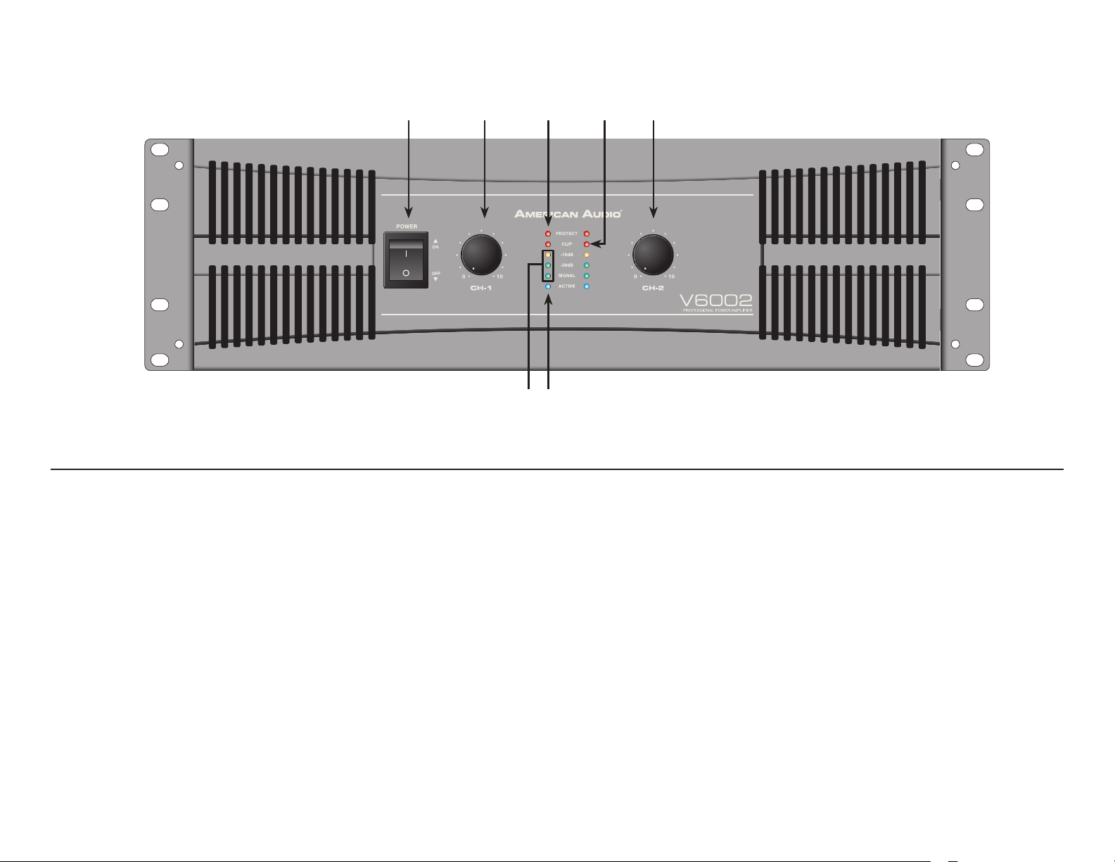
1. Power Switch - This switch is used to control the units main power.
432 5
6
Figure 1
2. Channel 1 Gain Control - This rotary knob is used to control the output signal of channel one. Turning the knob in a clockwise direction will increase signal output.
3. Protect Indicator - The red Protect LED will begin to glow when the channel goes into protect mode. When the channel goes into protect mode
all output for that channel will turn o. This is to protect any speakers connected to the channel.
4. Clip Indicator - This red LED will begin to ash when channel one begins to overload (clip). At this point channel one will begin to distort. Under
heavy clipping activity lower the channel one gain control to reduce the risk of damage to your speakers and amplier. This LED may glow when the
unit has been turned o, this is normal.
5. Channel 2 Gain Control - This rotary knob is used to control the output signal of channel two. Turning the knob in a clockwise direction will increase signal output.
6. Function Indicators - These indicators detail the operating mode of the amplier. These LEDs will also function as a power indicator.
7. Signal Indicators - These green and yellow LED’s will glow according to the average signal output.
©American Audio® - www.americanaudio.us - V Series™ Power Amplifier User Manual Page 5
Page 6
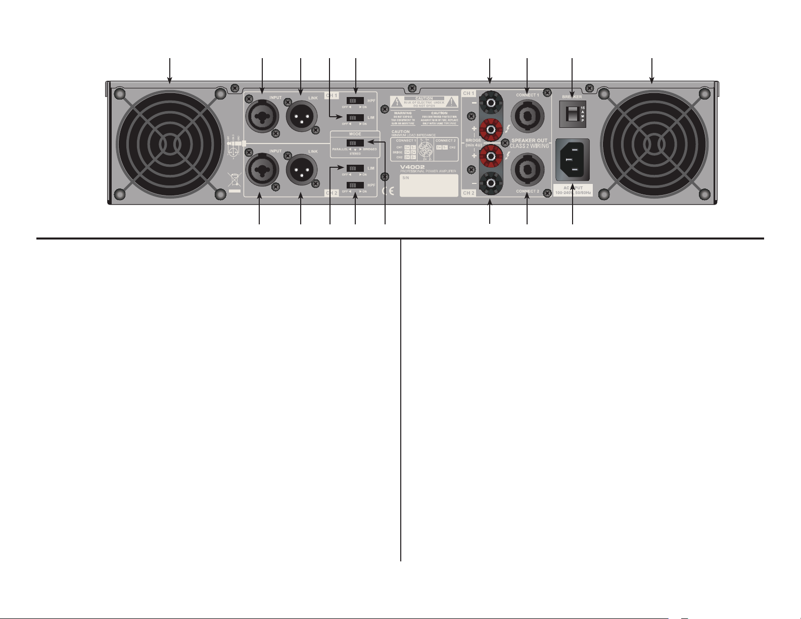
Rear Panel
V4002
1 87
3 4 5
62
1
16 15
1. Cooling Fans - Dual high speed cooling fans
2. Channel 1 XLR/1/4” Input - Channel two combo 3-pin XLR/1/4” balanced
input jack. The 1/4” female jack excepts either a balanced or unbalanced plug.
See page 9 for more details.
3. Channel 1 XLR Link Connector - This XLR jack is used to send a parrallel
signal from channel link jack to another device or amplier.
4. Channel 1 Limiter Switch - This switch is used to limit the input level of
channel 1. Use this function to avoid damage to your speakers.
5. Channel 1 High Pass Filter Switch - This switch controls the amplier’s lter
mode. The amplier can operate in three dierent lter modes; High Pass, Low
Pass, and By-Pass.
6. Channel 1 Output Jack/5 way Binding Post - Connect to your speaker’s
input jack. Red is positive signal and Black is negative signal.
7. Channel 1 Speakon Output - Optional speaker output connections. Use
pins 1+ and 1- of this 4-pole Speakon connector to connect to your speaker’s
Speakon input jack.
8. Breaker - The break acts in place of a common discardable fuse. The circuit
breaker will trip if the is a fault with the main voltage or if maximum output is
exceeded. Simply depress the breaker and power up the unit again.
11
10. Channel 2 Speakon Output - Optional speaker output connections. Use
pins 1+ and 1- of this 4-pole Speakon connector to connect to your speaker’s
Speakon input jack.
11. Channel 2 Output Jack/5 way Binding Post - Connect to your speaker’s
input jack. Red is positive signal and Black is negative signal.
12. Mode Switch - This switch controls the amplier’s operating mode. The
amplier can operate in three dierent modes; Mono Bridge, Stereo, or Parallel
Mono. The amplier is shipped in stereo mode.
13. Channel 2 High Pass Filter Switch - This switch controls the amplier’s
lter mode. The amplier can operate in three dierent lter modes; High Pass,
Low Pass, and By-Pass.
14. Channel 2 Limiter Switch - This switch is used to limit the input level of
channel 2. Use this function to avoid damage to your speakers.
15. Channel 2 XLR Link Connector - This XLR jack is used to send a parrallel
signal from channel link jack to another device or amplier.
16. Channel 2 XLR/1/4” Input - Channel one combo 3-pin XLR/1/4” balanced
input jack. The 1/4” female jack excepts either a balanced or unbalanced plug.
See page 9 for more details.
91014 13 12
Figure 2
9. AC Cord - Plug this cable into a standard wall outlet. Check that the voltage
in your area matches the ampliers required voltage.
©American Audio® - www.americanaudio.us - V Series™ Power Amplifier User Manual Page 6
Page 7
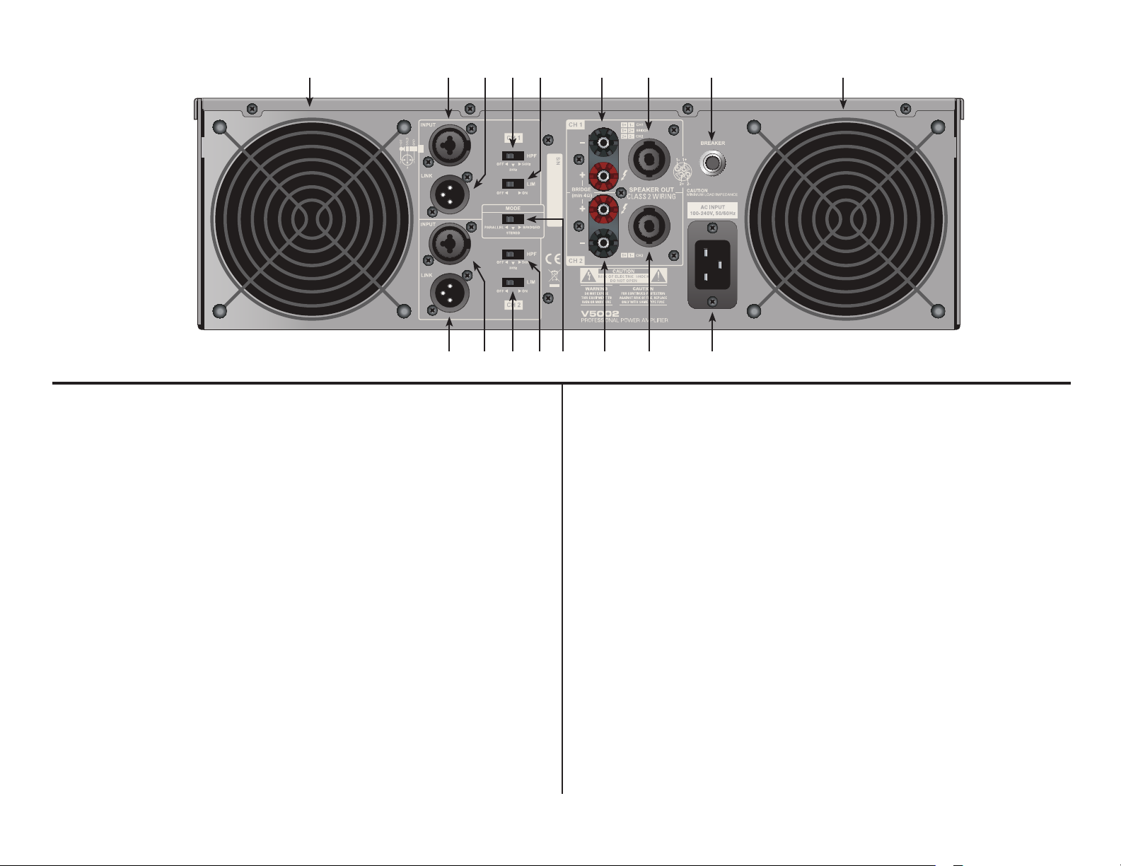
Rear Panel
V5002
V6002
1 2
16
1876543
Figure 3
15 14 13 12 11 10 9
1. Cooling Fans - Dual high speed cooling fans
2. Channel 1 XLR/1/4” Input - Channel two combo 3-pin XLR/1/4” balanced
input jack. The 1/4” female jack excepts either a balanced or unbalanced plug.
See page 9 for more details.
3. Channel 1 XLR Link Connector - This XLR jack is used to send a parrallel
signal from channel link jack to another device or amplier.
4. Channel 1 High Pass Filter Switch - This switch controls the amplier’s lter
mode. The amplier can operate in three dierent lter modes; High Pass, Low
Pass, and By-Pass.
5. Channel 1 Limiter Switch - This switch is used to limit the input level of
channel 1. Use this function to avoid damage to your speakers.
6. Channel 1 Output Jack/5 way Binding Post - Connect to your speaker’s
input jack. Red is positive signal and Black is negative signal.
7. Channel 1 Speakon Output - Optional speaker output connections. Use
pins 1+ and 1- of this 4-pole Speakon connector to connect to your speaker’s
Speakon input jack.
8. Breaker - The break acts in place of a common discardable fuse. The circuit
breaker will trip if the is a fault with the main voltage or if maximum output is
exceeded. Simply depress the breaker and power up the unit again.
©American Audio® - www.americanaudio.us - V Series™ Power Amplifier User Manual Page 7
9. AC Cord - Plug this cable into a standard wall outlet. Check that the voltage
in your area matches the ampliers required voltage.
10. Channel 2 Speakon Output - Optional speaker output connections. Use
pins 1+ and 1- of this 4-pole Speakon connector to connect to your speaker’s
Speakon input jack.
11. Channel 2 Output Jack/5 way Binding Post - Connect to your speaker’s
input jack. Red is positive signal and Black is negative signal.
12. Mode Switch - This switch controls the amplier’s operating mode. The
amplier can operate in three dierent modes; Mono Bridge, Stereo, or Parallel
Mono. The amplier is shipped in stereo mode.
13. Channel 2 High Pass Filter Switch - This switch controls the amplier’s
lter mode. The amplier can operate in three dierent lter modes; High Pass,
Low Pass, and By-Pass.
14. Channel 2 Limiter Switch - This switch is used to limit the input level of
channel 2. Use this function to avoid damage to your speakers.
15. Channel 2 XLR/1/4” Input - Channel one combo 3-pin XLR/1/4” balanced
input jack. The 1/4” female jack excepts either a balanced or unbalanced plug.
See page 9 for more details.
16. Channel 2 XLR Link Connector - This XLR jack is used to send a parrallel
signal from channel link jack to another device or amplier.
Page 8
Set Up
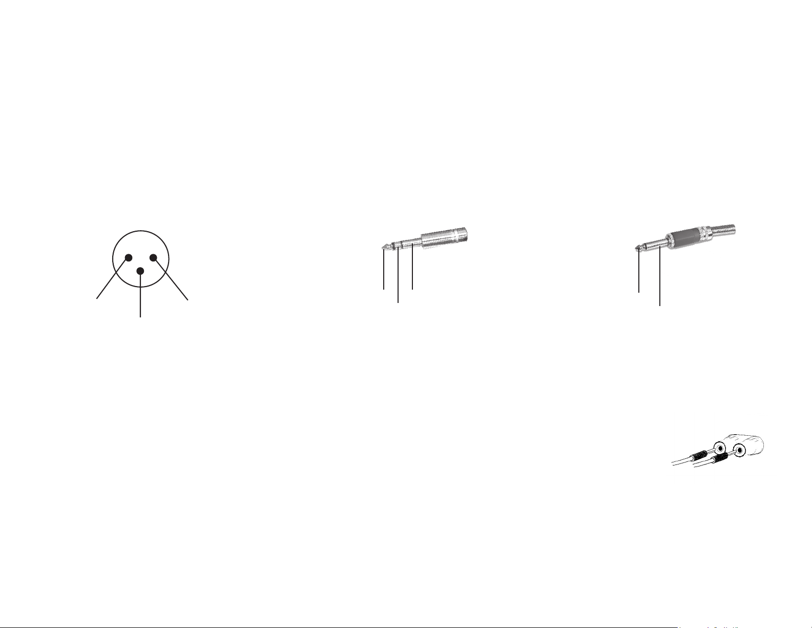
INPUTS - The V Series amplifier allows you to use two types of input connector per a channel, a XLR jack for balanced connections
and a 1/4” female jack that will accept balanced and unbalanced connectors. Use these connections to connect the output signal
from a mixer, cross-over or EQ to your V Series amplifier. A balanced connection is recommended for cable runs longer that 20ft.
When constructing your own XLR cables follow the pin configuration describe below for proper connections. For cable runs shorter
than 20ft. you may choose the 1/4” unbalanced input option. The 1/4” unbalanced input option may be more convenient for most
users due to the abundant supply of prefabricated cables available at your local audio dealer.
Male XLR Pin Confi guration:
US ITT Standard
Figure 4
2 Hot (+ data)
OUTPUTS:
3 Negative (- data)
1 Ground/Return/ 0v)
Balanced TRS 1/4” Plug
Figure 5
Hot (+)
Negative (-)
Ground/Shield
Unbalanced TS 1/4” Plug
Hot (+)
Negative (-)
Binding Post/Banana Plug - Connect your speakers to the binding post outputs on the rear of the amplier. The
speaker wire may be connect by bare wire (directly connected, usually for permanent connections), banana plug,
or spade connector. Connections are made to Channels 1 and 2 output’s for stereo mode or across the red ter-
minals of Channels 1 and 2 for Mono Bridge Mode.
Important Notice: Although a speaker will operate with the positive and negative leads plugged into either ter-
minal on the amplier binding post, be sure to plug the negative lead into the black terminal and positive lead
into the red terminal. Ensuring proper polarity will avoid speakers being out of phase, that can cause a loss of
bass response.
Figure 6
Figure 7
Important Notice: Banana Plugs - When connecting your speakers to the amplier using banana jacks; Be sure that the red and black
caps on the binding post are completely screwed in. Insert the banana jacks into the caps of the binding post, be sure that the banana
jack is inserted securely to avoid the risk of it popping out.
©American Audio® - www.americanaudio.us - V Series™ Power Amplifier User Manual Page 8
Page 9
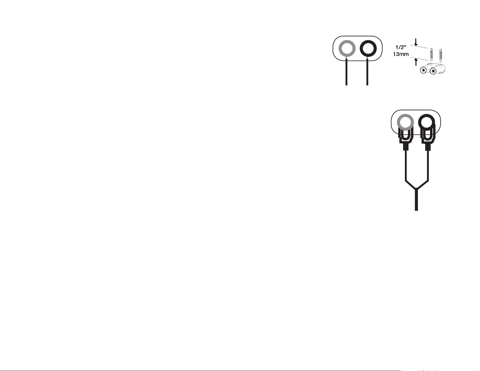
Bare Wire Connections: (Figure 8)
When connecting your speakers to the amplifier using bare wire; Unscrew the red and
black caps on the binding post, be sure not to completely remove or unscrew the red
and black caps. Strip back the wire insulation 1/2” (13mm). Insert the bare wire into the
hole that was reveled by unscrewing the binding post cap. After inserting the wire into
the binding post hole, screw the binding post cap down on the wire. To reduce the risk of
shock or damage to your amplifier, be sure that the wire connected to one binding post
does not come in contact with that of another.
Spade Connector: (Figure 9)
When connecting your speakers to the amplifier using spade connector; Unscrew the red and black caps on
the binding post, be sure not to completely remove or unscrew the red and black caps. Insert the spade connector in to the binding post and tighten the caps down on the spade connector. To reduce the risk of shock
or damage to your amplifier, be sure that the wire connected to one binding post does not come in contact
with that of another.
When connecting your speakers to the amplifier using banana jacks; Be sure that the red and black caps on
the binding post are tighten down completely. Insert the banana jacks into the caps of the binding post, be
sure that the banana jack is inserted securely to avoid the risk of it popping out.
Typical speaker output using bare wire. Insert
bare wire into the binding post and tighten.
Figure 8
Mono Bridge Connections:
Figure 9
Mono bridge operation connections will follow the above descriptions however, when operating in mono
bridge operation the speaker connections will run between the two positive (red) leads. Use channel two
positive output terminal for the negative connection and the channel one positive output terminal for the
positive connection.
Typical speaker output using
spade connectors. Insert
bare wire into the binding
post and tighten.
Stereo Connections Using the Neutrik Speakon output connectors:
Recent regulatory requirements in Europe have outlawed the use of the dual banana plug and force amp users to terminate their speaker
cables with spade lugs or bare wire ends. This is not advantageous to most users that want to recongure their systems or quickly
change out an amp. The Neutrik Speakon® connector provides the most convenient solution to this problem, eliminating the need for
spade plugs or bare wire end cables. Major speaker manufacturers have been using Speakon connectors on their products for years,
so chances are you are ready to use the Speakon connection. With Speakon connectors, you can connect straight from the amplier
to the speaker. The Speakon connector used on this amplier meets all known safety regulations. Once wired correctly, the connector
cannot be plugged in backwards, causing the type of inverted polarity situations that have become common with banana hookups. This
connection will provide a safe, secure and reliable method of connecting your speakers to your new amplier. You can purchase the
Speakon® NL4FC connectors from your local audio dealer.
©American Audio® - www.americanaudio.us - V Series™ Power Amplifier User Manual Page 9
Page 10
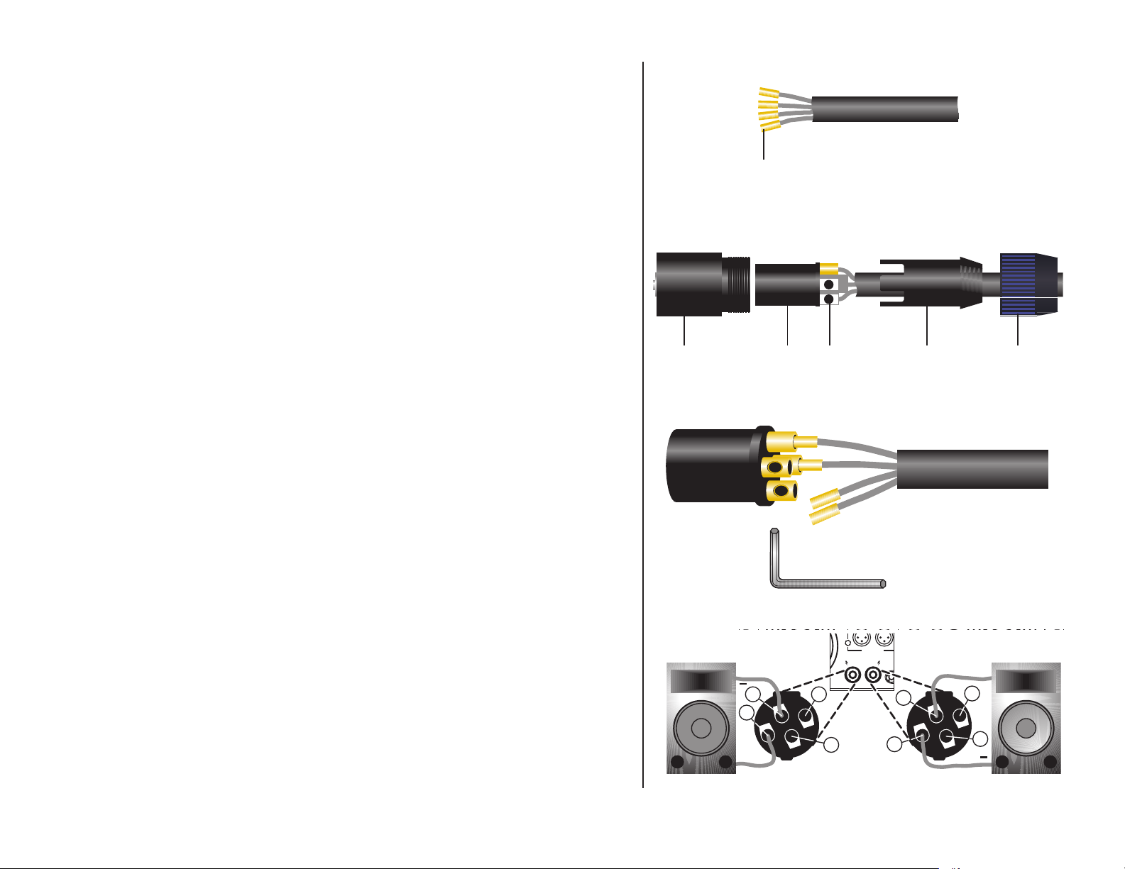
SPEAKON ASSEMBLY: You will need a pair of Neutrik Speakon® NL4FC
connectors. You will also need high-quality two or four conductor speaker
cable, a pair of needle-nosed pliers and a 1.5-mm Allen key to assemble the
Speakon connectors to your speaker wire. To assemble the Neutrik Speakon
NL4FC connector, complete the following steps:
1. Strip back 3/4-inch of the cable casing. Strip o 1/4-inch from the end of
each of the conductors down to bare wire, and insert the brass ttings. See
Figure 10.
2. Slide the cable tension clip (D) and the speakon coupler (E) through the
cable end. See Figure 11.
3. Insert each wire with the brass ttings into the top of appropriate slot of the
connector insert (B) as shown in Figures 12 and 13. Use a 1.5-mm Allen key
to tighten the connection. See Figure 12.
Figure 10
4-Conductor Speaker CableBrass Inserts
Figure 11
4. Be sure to properly match the positive (+) and negative (–) leads of each
wire. See Figure 13.
5. Slide the connector insert (B) into the connector housing (A), making sure
that the large notch on the outer edge of the insert lines up with the large
groove on the inside of the connector housing. The insert should slide easily
through the housing and out the other side until it extends approximately 3
/4-inch from the end of the housing.
6. Slide the cable tension clip (D) along the cable and insert into the housing
(A), making sure that the large notch lines up with the large groove on the
inside of the connector housing (A). The cable tension clip (D) should slide
easily into the housing until only 3 /8-inch of the cable tension clip (D) extends
from the back end of the connector.
7. Slide the coupler (E) along the cable and screw it onto the end of the
housing (A). Before tightening, you may want to test the connector to make
sure it has been assembled properly.
Figure 12
Figure 13
D EBA C
INPUT T UINPUT BA ANCE
1 COLD
C 1C 2
CAUTION
MINIMUM LOAD IMPEDANCE 2 OHM PERCHANNEL 4 OHM BRIDGE
- BIDE +
N
C 1C 2
-+
+1
-1
120 60
4800 ATTS
-+
+2
+
+2
SPEAKON 1+ HOT
UTPUTS
+1
-1
+
+2
+2
©American Audio® - www.americanaudio.us - V Series™ Power Amplifier User Manual Page 10
Page 11

OPERATING MODES: Always configure your amplifier operating mode before beginning operation. If you want to change it dur-
ing performance. You must decrease the gain controls to their lowest levels to protect the speakers from any popping noise.
Stereo Operation - Page 14/Figure 14 details an example of a typical stereo set-up. Connect your inputs into channels one and
two of the amplifier. Connect your speakers to the outputs on the rear of the amplifier. Be sure that your front gain controls are turned
down to their lowest level (full counter-clockwise). Turn your amp on. Turn your input source level up. Use your front gain controls to
regulate the output volume. Be sure not to raise the volume to the clip level, however an intermittent clip signal is acceptable.
Mono Bridge Operation - Page 14/Figure 15 details a mono bridge set-up. Be sure your amplifier and all other audio equipment
is powered down. Flip the Stereo/Mono Bridge switch to the Mono Bridge position. Connect an input signal to channel one. Connect
your speaker across the red output binding post on the rear of your amplifier. Turn your equipment on (your amplifier should always
be the last item you turn on). Apply an input source signal to your amplifier. Turn channel two gain up. Use the channel one gain to
regulate your amplifier output.
Bridged-Mono Mode Caution - The voltage across the output terminals of a bridged V Series™ amplifier may equal or exceed
100 volts RMS and may be as high as 130 volts. Use fully insulated CLASS ONE wiring, and the load must be rated for up to 2500 watts
(@4 ohms)
Parallel Mono - “Parallel ” ties the two channel line inputs together so that they will both be driven by the same signal, without the
need for external jumpers or wiring. Both amplier channels will operate independently. Though they carry the same signal, their gain
controls aect only their respective channels, and they both must use their respected speaker outputs. Never attempt to parallel the
speaker outputs, this may cause serious damage to your amplier! This mode is recommended when using the V Series™ to run bass
speakers, to achieve better low end. To run in parallel mono mode connect your system as you would if you were going to run in stereo
mode. Then ip the mode switch to “MONO.” Be sure the amp is o or the power is disconnected before making any changes.
©American Audio® - www.americanaudio.us - V Series™ Power Amplifier User Manual Page 11
Page 12
Mono Subwoofer - This operation is similar to the Stereo Subwoofer operation but in mono. When running subwoofers it is usually
recommended to run them in mono mode to achieve a cleaner tighter low end. This operation allows you to run several subwoofers
down to a minimum of 4 ohms. To avoid amplifier overheating, never run the amplifier below 8 ohms in this mode. Set up this mode
as you would a standard stereo set up. In this mode you may use the frequency adjustment on the rear of the amp, to control the bass
frequency output level. Frequencies may be adjusted from 20Hz to 200Hz.
PROTECTION:
Limiter - The amps come with a built in limiter. When the input signal overloads, the “CLIP LED’s” indicate a signal overload, at this
time, the master volume should be lowered to reduce distortion. If the input gain level is not reduced the built-in limiter will activate.
During signal overload, the limiter will reduce the input audio signal enough to minimize the amount of clipping. A limiter takes the gain
of an overloading signal and reduces it, the reduction in gain reduces distortion that can cause damage to your speakers and ampli-
fier. During normal operation below clipping, and momentary clips on peaks, the limiter does not affect the audio signal and is inaudible. It will allow brief clipping of peaks and will only activate when continuous, hard clipping occurs. During excessive clipping the
limiter will reduce the audio signal enough to minimize the amount of clipping. When the input signal decreases enough that clipping
ends, the limiter will deactivate and cease its gain reduction. The limiter has a fixed threshold and can not be adjusted.
Safe Power Levels at Different Output Loads:
8-Ohm Loads: The amplifier can operate at practically any power level without risk of overheating. However, if it is pushed hard
enough to continually light the “CLIP ” indicator, the V4002 average output power can reach 3200 watts, the V5002 can reach 4000
Watts, and the V6002 can reach 5000 Watts.
4-Ohm Loads: If the “CLIP” indicator flashes occasionally, the amplifier is approaching its maximum long-term power capacity. If it is
lit about half the time, the amplifier channel will probably go into thermal protection within a few minutes.
Short Circuit Protection - The V Series™ amplifiers all come with built-in Output Short Circuit Protects. The Output Short Circuit
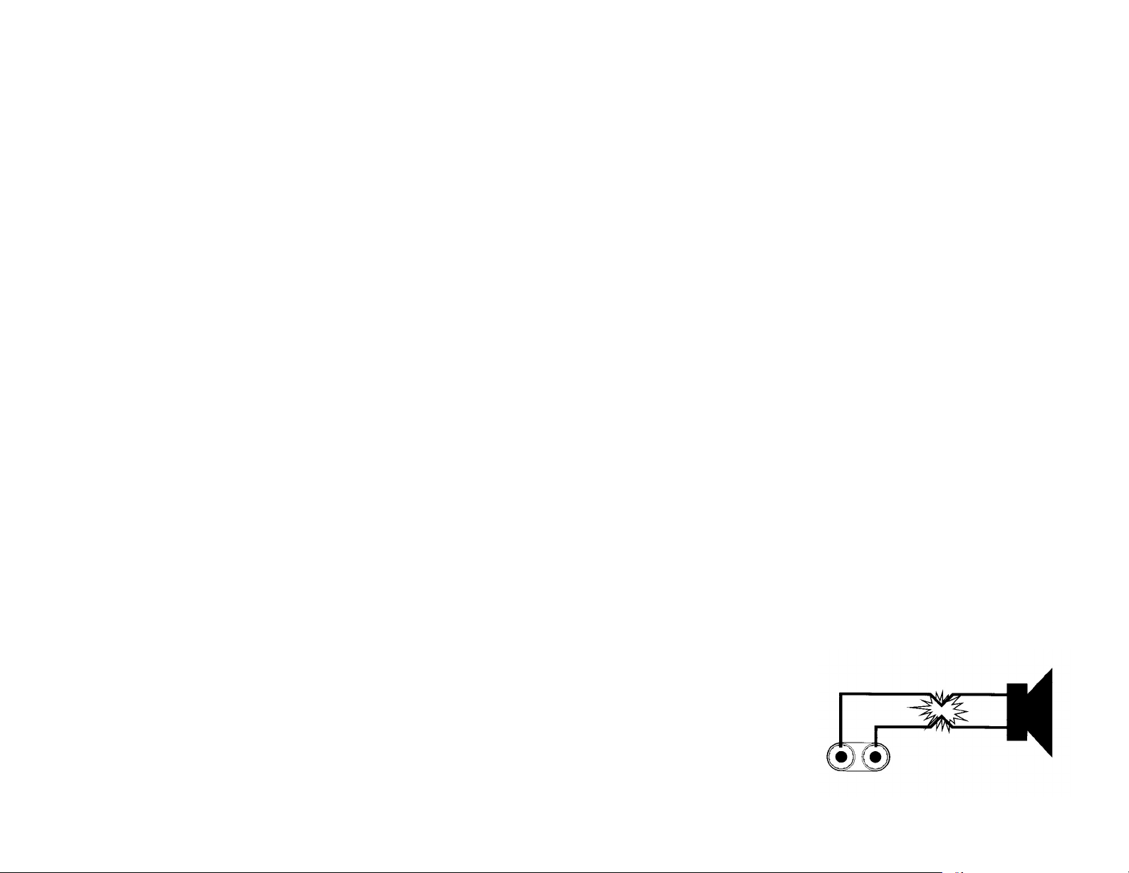
Protection protects the output devices of the amplifier from short circuits and stressful loads. If your speaker lines short, the amplifier automatically detects this problem and discontinues operation for that channel. If one side of your amplifier becomes shorted and
goes into protect mode, the other side will continue to operate normally. During short circuit protection, the "Clip" LED and “Protect"
LED will light simultaneously indicating amplifier fault. All channel output during the “Short Circuit Protection" will be interrupted (i.e.
no sound out
©American Audio® - www.americanaudio.us - V Series™ Power Amplifier User Manual Page 12
Page 13

put). Short Circuit Protection can usually be traced back to the signal output line (i.e. speaker line). Check the line from the output ter-
minal of the amplifier to the speaker. If this line good, check the internal speaker connections and components. A short circuit will usually be traced to a bad cable or a bad speaker component and is rarely traced to the amplifier itself.
Thermal Protection - Dual variable speed fans on the V Series amplifier provide adequate cooling. During low level output the fans
run at normal speeds. During high output and as heat raises, (exceeding 90°C.), the fans will run at higher speeds to aid the cooling
process. If the heatsink temperature exceeds 91°C., the amplifier will mute until the amplifier cools down. When the amplifier cools
below 90°C., the amplifier will return to normal operations. Be sure not to operate your amplifier below the minimum load ratings to
reduce the risk of overheating problems.
Input/Output Protection - The input circuits are isolated by 10k resistors. An ultrasonic network uncouples RF from the output and
helps keep the amplifier stable with reactive loads.
Operating Voltage (AC Mains) - The serial number label indicates the correct AC main voltage. Connecting to the wrong voltage is
dangerous and may damage the amplifier. Always be sure the source voltage for your areas matches the required voltage for your
amplifier.
Gain Controls - The gain controls are located on the front panel and are calibrated in 2dB of attenuation from full gain. It is best to
adjust the amplifier so no “hissing” is heard from speakers with no music being played, this will ensure the lowest possible distortion
during normal operation.
AMPLIFIER FEATURES:
LINK - Thru will allow the user to daisy-chain one amplifiers signal input into another amplifier. Plug the signal source outputs into the
first amplifier’s input, patch from the amplifier’s LINK jacks to the next amplifier’s input, and so on, daisy-chaining as many amplifiers
as there is no excessive level loss. Is not affected by crossover setting.
OPERATING VOLTAGE (AC MAINS) - The serial number label indicates the correct AC main voltage. Connecting to the wrong voltage is dangerous and may damage the amplifier.
GAIN CONTROLS - The gain controls are located on the front panel and are calibrated in 2dB of attenuation from full gain. It is best to
adjust the amplifier so no “hissing” is heard from speakers with no music being played, this will ensure the lowest possible distortion
during normal operation.
LED INDICATORS - Each channel has five LEDS. Two LEDs indicate signal level activity; two green LEDs. One yellow LED indicates
signal clipping. One red LED indicates protections mode for shorts/ overload. One blue LED indicates power for each individual chan-
nel.
©American Audio® - www.americanaudio.us - V Series™ Power Amplifier User Manual Page 13
Page 14
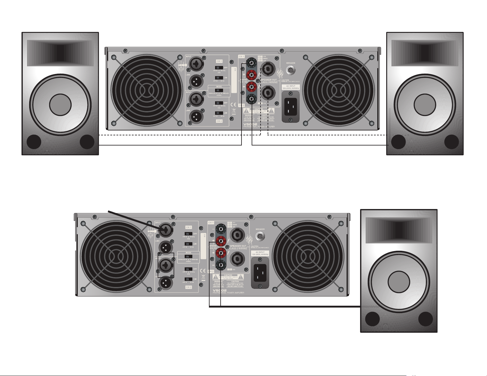
TYPICAL STEREO OUTPUT CONNECTIONS
SPEAKERS
4 OHM MINIMUM
Use Channel 1 Inputs Only (XLR or 1/4” Jacks)
Figure 14
Use Speakon or Banana Jacks
SPEAKERS
4 OHM MINIMUM
TYPICAL MONO BRIDGE SET-UP
Figure 15
X
Use the two positive binding post
termainals (red) for speaker output.
SPEAKERS
8 OHM MINIMUM
©American Audio® - www.americanaudio.us - V Series™ Power Amplifier User Manual Page 14
Page 15

The V Series carries a one year limited warranty. We recommend you fill out the enclosed warranty card to validate your purchase. All
returned service items whether under warranty or not, must be freight pre-paid and accompany a R.A. (return authorization) number. If the
mixer is under warranty, you must provide a proof of purchase invoice. You may obtain a R.A. number by contacting our customer support
team on our toll free number. Please contact American Audio® customer support at (800) 322-6337 for a R.A. number. All package
not displaying a R.A. number on the outside of the package will be returned to the shipper.
1-YEAR LIMITED WARRANTY
A. American Audio® hereby warrants, to the original purchaser, American Audio® products to be free of manufacturing defects in material and work-
manship for a period of 1 Year (365 days) from the date of purchase. This warranty shall be valid only if the product is purchased within the United
States of America, including possessions and territories. It is the owner’s responsibility to establish the date and place of purchase by acceptable
evidence, at the time service is sought.
B. For warranty service, send the product only to the American Audio® factory. All shipping charges must be pre-paid. If the requested repairs or
service (including parts replacement) are within the terms of this warranty, American Audio® will pay return shipping charges only to a designated
point within the United States. If the entire instrument is sent, it must be shipped in its original package. No accessories should be shipped with
the product. If any accessories are shipped with the product, American Audio® shall have no liability whatsoever for loss of or damage to any such
accessories, nor for the safe return thereof.
C. This warranty is void if the serial number has been altered or removed; if the product is modied in any manner which American Audio® concludes, after inspection, aects the reliability of the product; if the product has been repaired or serviced by anyone other than the American Audio®
factory unless prior written authorization was issued to purchaser by American Audio®; if the product is damaged because not properly maintained
as set forth in the instruction manual.
D. This is not a service contract, and this warranty does not include maintenance, cleaning or periodic check-up. During the period specied above,
American Audio® will replace defective parts at its expense, and will absorb all expenses for warranty service and repair labor by reason of defects
in material or workmanship. The sole responsibility of American Audio® under this warranty shall be limited to the repair of the product, or replacement thereof, including parts, at the sole discretion of American Audio®. All products covered by this warranty were manufactured after January 1,
1990, and bear identifying marks to that eect.
E. American Audio® reserves the right to make changes in design and/or improvements upon its products without any obligation to include these
changes in any products theretofore manufactured.
F. No warranty, whether expressed or implied, is given or made with respect to any accessory supplied with products described above. Except to
the extent prohibited by applicable law, all implied warranties made by American Audio® in connection with this product, including warranties of
merchantability or tness, are limited in duration to the warranty period set forth above. And no warranties, whether expressed or implied, including
warranties of merchantability or tness, shall apply to this product after said period has expired. The consumer’s and or Dealer’s sole remedy shall
be such repair or replacement as is expressly provided above; and under no circumstances shall American Audio® be liable for any loss or damage,
direct or consequential, arising out of the use of, or inability to use, this product.
G. This warranty is the only written warranty applicable to American Audio® products and supersedes all prior warranties and written descriptions
of warranty terms and conditions heretofore published.
©American Audio® - www.americanaudio.us - V Series™ Power Amplifier User Manual Page 15
Page 16

NOTES
American Audio® - www.americanaudio.us - V Series™ Power Amplifier User Manual Page 16
Page 17
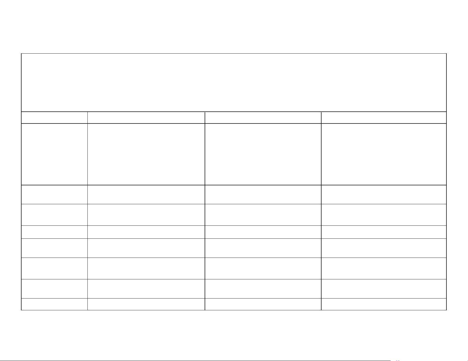
V SERIES SPECS
Power supply: AC 100V, 50/60Hz (Japan)
AC 110V, 60Hz (Colombia)
AC 120V, 60Hz (U.S.A. and Canada)
AC 127V, 60Hz (Mexico)
AC 220V, 50Hz (Chile and Argentina)
AC 220V, 60Hz (Philippines and Korea)
AC 230V, 50Hz (Europe, New Zealand, South Africa, and Singapore)
AC 240V, 50Hz (Australia and U.K.)
MODEL: V4002 V5002 V6002
Output Power: 1100W RMS per Channel @ 4 Ohms 1400W RMS per Channel @ 4 Ohms 1800W RMS per Channel @ 4 Ohms,
1kHz, 0.1% THD 1kHz, 0.1% THD 1kHz, 0.1% THD
700W RMS per Channel @ 8 Ohms 850W RMS per Channel @ 8 Ohms, 1100W RMS per Channel @ 8 Ohms,
1kHz, 0.1% THD 1kHz, 0.1% THD 1kHz, 0.1% THD
3200W RMS @ 4 Ohms, 4000W RMS @ 4 Ohms, 5000W RMS @ 4 Ohms,
1kHz, 1% THD (Bridged Mode) 1kHz, 1% THD (Bridged Mode) 1kHz, 1% THD (Bridged Mode)
Total Harmonic Less Then 0.03% (20Hz - 20kHZ @ Less Then 0.03% (20Hz - 20kHZ @ Less Then 0.03% (20Hz - 20kHZ @
Distortion (THD): 8 Ohms 8 Ohms 8 Ohms
Frequency 0/-0.5db; 20Hz-20KHz 5Hz to 50kHz to -3dB 5Hz to 50kHz to -3dB
Response: 0/-3dB; 5Hz - 60KHz
Slew Rate: 40V/msec 40V/msec 40V/msec
Damping Factor @ 350 >300 >300
8 Ohm:
Impedance: 30K Ohms Balanced 20K Ohms Balanced 20K Ohms Balanced
15K Ohms Unbalanced 10K Ohms Unbalanced 10K Ohms Unbalanced
Dimensions 16.5” x 19” x 3.5” 19” x 19” x 5.25” 19” x 19” x 5.25”
(LxWxH): 420 x 482 x 88mm 482 x 482 x 132mm 482 x 482 x 132mm
Weight: 46lbs/20.8Kgs 79lbs/36Kgs 83lbs/37.3Kgs
American Audio® - www.americanaudio.us - V Series™ Power Amplifier User Manual Page 17
Page 18

©American Audio® World Headquarters:
6122 S. Eastern Ave. Los Angeles, CA 90040 USA
Tel: 323-582-3322 Fax: 323-725-6100
Web: www.AmericanAudio.us E-mail: [email protected]
American DJ Europe
Junostraat 2
6468 EW Kerkrade
Netherlands
[email protected] / www.americandj.eu
Tel: +31 45 546 85 00 / Fax: +31 45 546 85 99
 Loading...