

Page 1
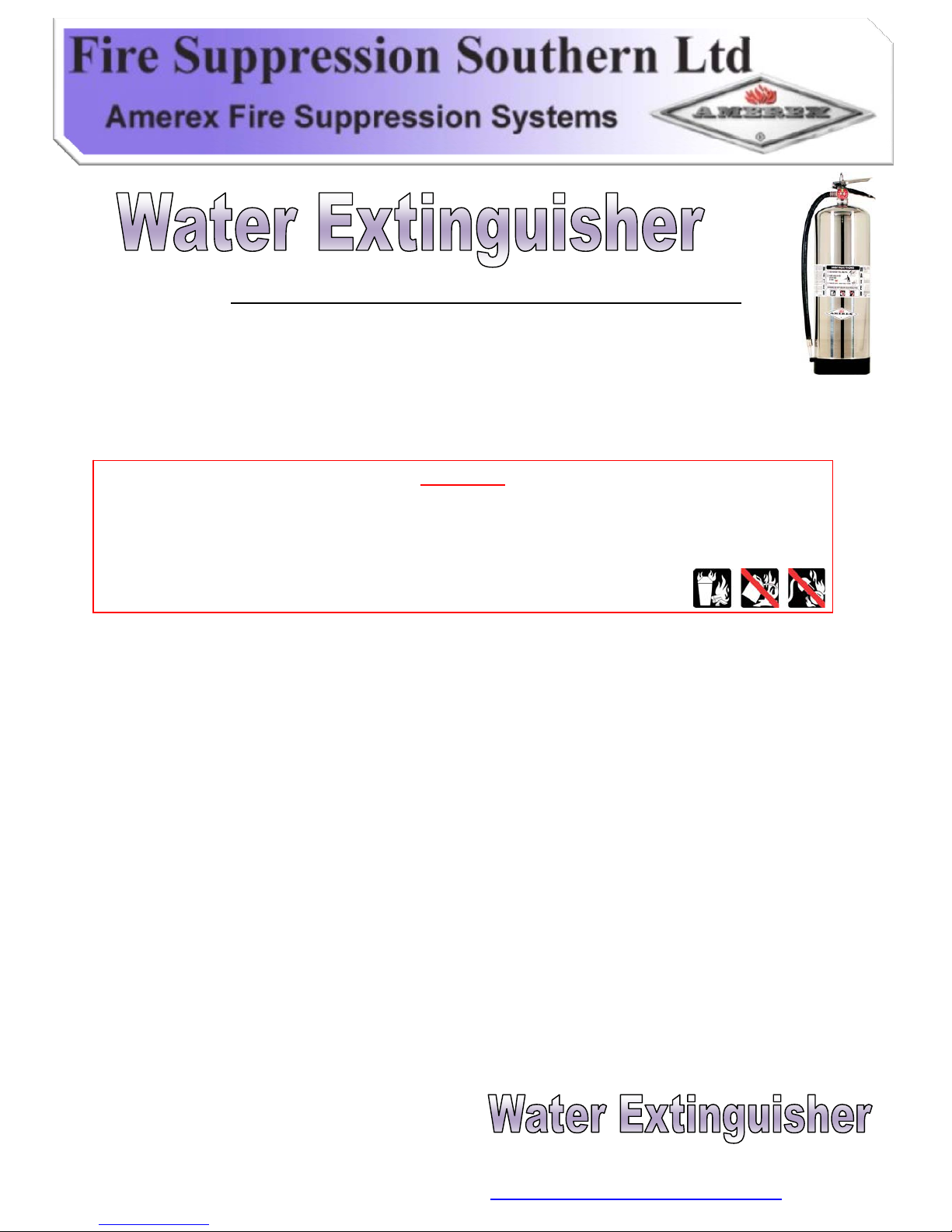
INSPECTION, MAINTENANCE AND RECHARGE SERVICE MANUAL
NO. 05601, FOR
AMEREX MODEL 240
2½ GALLON STORED PRESSURE STAINLESS STEEL WATER FIRE EXTINGUISHERS
***
RECHARGE FIRE EXTINGUISHERS IMMEDIATELY AFTER ANY USE ***
WARNING
DO NOT USE THIS EXTINGUISHER ON CLASS C FIRES INVOLVING ENGE RGIZED
ELECTRICAL EQUIPMENT, CLASS D OR ANY FLAMMABLES THAT WILL REACT WITH WATER.
PROTECT FROM FREEZING UNLESS CHARGED WITH AN AMEREX MODEL 506 LOADED
STREAM/ANTI-FREEZE CHARGE
All fire extinguishers should be installed, inspected and maintained in accordance with the National Fire Protection
Association standard titled ‘Portable Fire Extinguishers’, NFA-10 and the requirements of local authorities having
jurisdiction.
When maintenance is indicated it should be performed by trained persons having proper equipment. Fire
extinguishers are pressure vessels and must be treated with respect and handled with care. They are mechanical
devices and require periodic maintenance to be sure that they are ready to operate properly and safely. Amerex
and Fire Suppression Southern strongly recommend that the maintenance of portable fire extinguisher be done by
a trained professional – your authorized Amerex Distributor.
Amerex Corporation makes original factory parts available to insure proper maintenance – use of substitute parts
releases Amerex and Fire Suppression Southern of its warranty obligations. Amerex parts have machined surfaces
and threads that are manufactured to exacting tolerances. O-rings, hoses, nozzles, and all metal parts m eet
precise specifications and are subjected to multiple in-house inspections and tests for accept ability. There are
substitute parts available that are incorrectly labelled as UL component parts; some are advertised as Amerex type.
None of these meet UL requirements and all of them void the Amerex and Fire Suppression Southern extinguisher
warranty and UL listing. DO NOT SUBSTITUTE!
Page 1 of 8
Unit D4 Seedbed Business Centre, Vanguard Way, Shoeburyness, Essex, SS3 9QY,
T: 01702 384038 F: 01702 384043 E: [email protected]
Page 2
REFERENCES IN THIS MANUAL
NFPA-10 Portable Fire Extinguishers
CGA C-1 Methods of Hydrostatic Testing of Compressed Gas Cylinders
CGA C-6 Standard for Visual Inspection of Compressed Gas Cylinders
AMEREX AND FIRE SUPPRESSION SOUTERN LTD DO NOT SERVICE, MAINTAIN OR RECHARGE FIRE
EXTINGUISHERS. THIS MANUAL IS PUBLISHED AS A GUIDE TO ASSIST SERVICE PERSONNEL IN THE
INSPECTION, MAINTENANCE AND RECHARGE OF AMEREX FIRE EXTINGUISHERS ONLY. NO
INSTRUCTION MANUAL CAN ANTICIPATE ALL POSSIBLE MALFUNCTIONS THAT MAY BE
ENCOUNTERED IN THE SERVICE OF FIRE EXTINGUISHERS. AMEREX AND FIRE SUPPRESSION
SOUTHERN ASSUMES NO LIABILITY FOR SERVICE, MAINTENANCE OR RECHARGE OF FIRE BY
PUBLISHING THIS MANUAL.
Page 2 of 8
Unit D4 Seedbed Business Centre, Vanguard Way, Shoeburyness, Essex, SS3 9QY,
T: 01702 384038 F: 01702 384043 E: [email protected]
Page 3
INSPECTION
This extinguisher should be INSPECTED at regular intervals (monthly or more often if circumstanced dictate) to
insure that it is ready for use. INSEPCTION (NFPA 10 6.2) is a ‘Quick Check’ that an extinguisher is available and
will operate. It is intended to give reasonable assurance that the extinguisher is fully charged and operable. This is
done by seeing that is it in its designated place, that it has not been actuated or tampered with, and that there is no
obvious physical damage or condition to prevent operation.
MAINTENANCE
At least once a year (or more frequently if indicated by an inspection) MAINTENANCE {NFPA 10 6.3) should be
performed. MAINTENANCE is a ‘Through Check’ of the extinguisher. It is extended to give maximum assurance
that an extinguisher will operate effectively and safely. It includes a thorough examination and any necessary repair
on replacement. It will normally reveal the need for hydrostatic testing.
MAINTENANCE/ SERVICE PROCEDURE
1. Clean extinguisher to remove dirt, grease or foreign material. Check to make sure that the instruction
nameplate is securely fastened and legible. Inspect the cylinder for corrosion, abrasion, dents or weld
damage. If any of these conditions are found and you doubt the integrity of the cylinder, hydrostatically test,
using the proof pressure method and a suitable cage, in accordance with CGA C-6 and NFPA 10. NOTE:
When cleaning avoid the use of solvents are the pressure gauge they could seriously damage the
plastic gauge face.
2. Inspect the extinguisher for damaged, missing or substitute parts. Only factory replacement parts are
approved for use on Amerex Fire Extinguishers.
3. Weigh extinguisher and compare with weight printed on the maintenance section of the nameplate.
Recharge if weight is not within the indicated allowable tolerances.
4. Check the date of manufacture on the extinguisher hanger loop. Cylinder must be hydrostatically tested
every 5 years to the test pressure indicated on the nameplate.
5. Visually inspect the pressure gauge.
•If bent, damaged or improper gauge, depressurize and replace
•If pressure is low, check for leaks
•If over-pressurized (overcharged) reduce to 100 psi (690 kPa) through the pressure valve and check for leaks
6. Inspect the foot stand (base). If cracked or broken replace with the appropriate foot stand (see parts list)
7. Inspect ring pin for freedom of movement. Replace if bent or if removal appears difficult.
8. Inspect discharge lever for dirt or corrosion that might impair freedom of movement. Inspect carrying
handle for proper installation. If lever, handle or rivets are damaged or distorted replace with proper
Amerex Parts.
Page 3 of 8
Unit D4 Seedbed Business Centre, Vanguard Way, Shoeburyness, Essex, SS3 9QY,
T: 01702 384038 F: 01702 384043 E: [email protected]
Page 4
9. Remove hose & nozzle assembly. Inspect hose gasket (o-ring), hose and nozzle assembly for damage,
replace as necessary. Blow air through hose & nozzle to insure passage is clear of foreign material.
10. Examine the air pressurizing valve (Schrader) for damage. The cap should be in place to prevent leaking.
Inspect the valve assembly for corrosion or damage to hose thread connections. Replace valve assembly
or component parts as necessary following the proper depressurization and recharge procedures.
11. Install hose and nozzle assembly
12. Install new tamper seal if broken and record service data on the extinguisher inspection tag.
13. Rehang the extinguisher on the wall hanger bracket making that it fits the hanger bracket properly –
replace the bracket if necessary. Note: when a Loaded Stream/Anti-freeze charge is used to freeze
protect this extinguisher, a complete discharge and maintenance is required ANNUALLY. Use only
the Amerex Model 560 charge and follow the instructions printed on the carton
RECHARGE
RECHARGE (NFPA 10 6.4) is the replacement of the extinguishing agent and also includes the
expellant for this type of extinguisher.
WARNING:
a. Before attempting to recharge be sure this extinguisher is completely depressurized.
b. Use a REGULATED pressurizing source (either air or nitrogen). Set the regulator no more than 25
psi (175 kPa) higher than the gauge operating pressure.
c. Check and calibrate regulator gauge at frequent intervals. The regulator gauge should be used to
determine when the intended charging pressure has been reached. Do not use the extinguishe r
gauge for this purpose.
d. Never leave an extinguisher connected to a regulator of a high-pressure source for an extended
period of time. A defective regulator could cause the cylinder to rupture due to excessive pressure.
Page 4 of 8
Unit D4 Seedbed Business Centre, Vanguard Way, Shoeburyness, Essex, SS3 9QY,
T: 01702 384038 F: 01702 384043 E: [email protected]
Page 5
RECHARGING PROCEDURE
1. Complete the ‘Maintenance/Service Procedure’ items 1 through 10.
2. Discharge all remaining pressure and water (or anti –freeze solution) making sure there is no
remaining air pressure.
3. Remove the valve assembly and disassemble by removing downtube assembly (use a wrench on
the brass retainer, not the plastic tube), spring and valve stem assembly. Remove collar o-ring from
the valve and plastic fill tube from the cylinder.
4. Thoroughly rinse all parts with clean water and wipe dry with a soft cloth. Blow the valve out with air
or nitrogen. Inspect the collar o-ring, valve stem and spring – replace parts if worn or damaged.
Lubricate the collar o-ring and small o-ring on the valve stem with Visilox V-11 (do not lubricate the
valve stem seal). Inspect the downtube. If it is cracked, deformed or does not have a threaded brass
spring retainer replace with P/N 00404. Inspect downtube o-ring, replace if necessary.
5. Rinse the cylinder with clean water and inspect the interior following CGA Visual Inspe ction
Standard C-6.
6. Firmly replace the plastic fill tube with clean water until it overflows (2½ U.S. gallons [9½ litres]).
NOTE: THE FIRE SUPPRESSION SOUTHERN WARRENTY DOESN NOT COVER STAINLESS
STEEL EXTINGUISHERS FILLED WITH WATER WHICH CONTAINS IN EXCESS OF 40PPM
OF CHLORIDES. IN MANY AREAS WATER INCLUDES HIGH LEVELS OF CHLORIDES. THE
AMEREX MODEL 507 CORROSION INHIBITOR SHOULD BE USED IN ALL CASES WHERE
THE CHLORIDE ONTENT OF THE WATER IS SUSPECT.
7. Install a ‘Verification of Service’ collar around the neck of the cylinder. Install valve assembly to the
cylinder and properly align. CAUTION! : Hand tighten the valve collar nut 100-125 in. Lbs. Max
(1.15 – 1.44 KG/m). Over-tightening with a wrench will damage the valve.
8. Remove cap from the air pressurizing valve on the side of the valve body and pressurize with 100
psi (690 kPa) using air or nitrogen. NOTE: A 02141 fill adapter may also be used by installing to the
female valve outlet (where the hose assembly attaches). The pressure regulator should be set to no
more than 125 psi (862 kPa). Replace pressure valve cap. The cap must be in place to insure that
valve will not leak.
9. Check the collar, gauge, air pressurizing valve, cylinder welds and valve orifice for leaks using l eak
detection fluid or a solution of soapy water. Remove leak detection fluid from the valve assembly by
blowing out with air and wipe exterior of the extinguisher to dry.
10. Install hose and nozzle assembly.
11. Install ring pin with ring facing front of extinguisher. Install new tamper seal. Record recharge date and
attach new recharge tag.
Page 5 of 8
12. Weigh assembled extinguisher and confirm that the total weight is within the allowable tolerances
indicated in the Maintenance section on the extinguisher nameplate.
Unit D4 Seedbed Business Centre, Vanguard Way, Shoeburyness, Essex, SS3 9QY,
T: 01702 384038 F: 01702 384043 E: [email protected]
Page 6
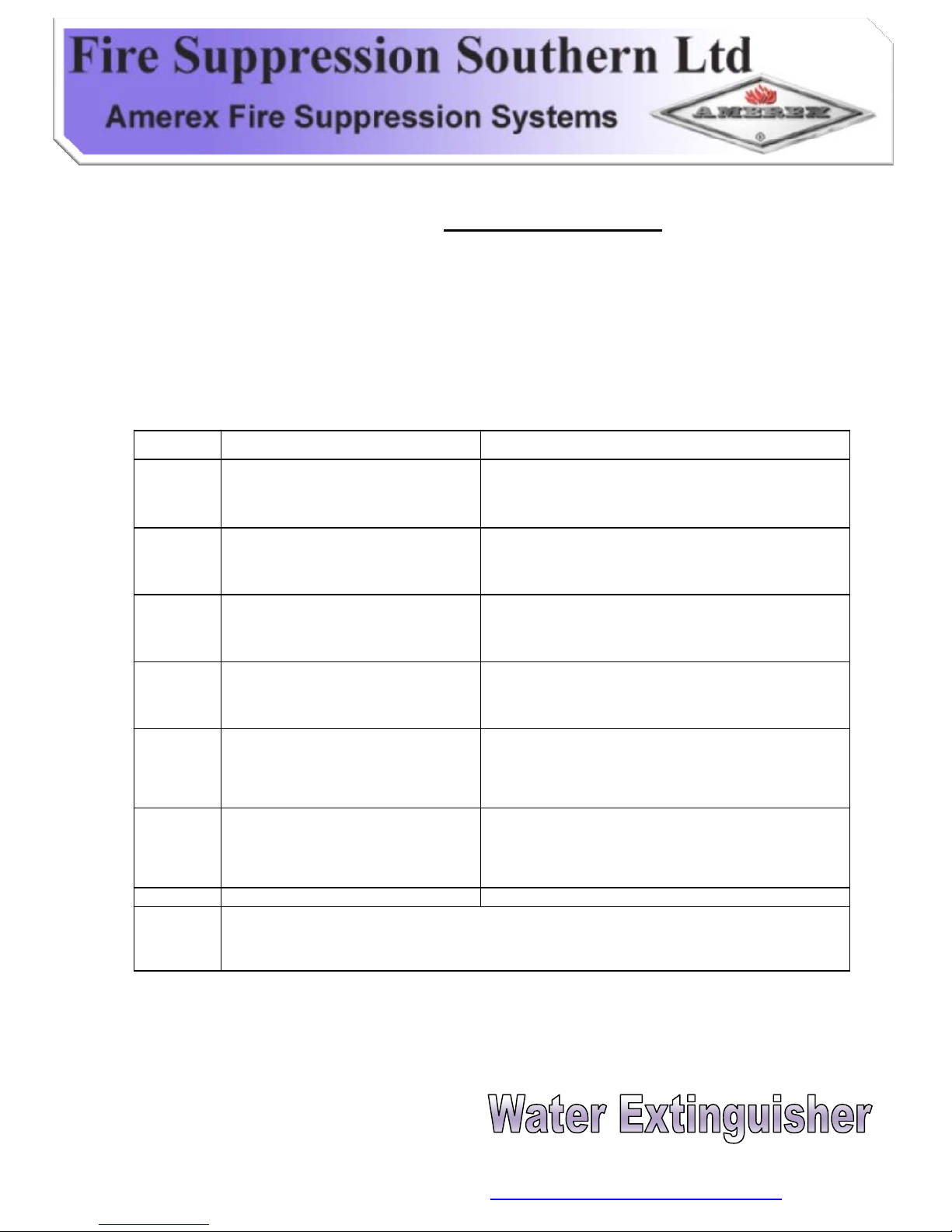
TROUBLESHOOTING GUIDE
WARNING: Determine the source of a leak before the extinguisher is depressurized. THE EXTINGUISHER
MUST BE COMPLETELY DEPRESSURIZED BEFORE ANY ATTEMPY IS MADE TO DEVALVE IT AND
CORRECT AND LEAKAGE PROBLEM. To depressurize d hold the extinguisher in an inverted position and
slowly squeeze the discharge handle. Some water remaining in the downtube will be discharged, so care should
be taken in the area used depressurizing. Thoroughly clean all valve parts after depressuri zing and valve
removal.
PROBLEM CORRECTIVE ACTION
1.
Leak at collar o-ring
2.
Leak through valve
3.
Leak around gauge threads
4.
Defective gauge
5.
Leak in cylinder
6.
Broken Footstand
Pressure gauge threads are coated with a special epoxy at the factory. For easy removal
soak the valve assembly (minus the downtube assembly) in hot water (180˚F/82˚C) for two to
four minutes. Remove gauge with a 7/16” open end wrench.
Install new P/N 02520 Footstand using Dow corning
RTV-732 Silicone Rubber adhesive, Amerex P/N
04488
Contact Fire Suppression Southern Ltd if under
warranty, otherwise mark ‘REJECTED’ and return to
owner
Remove defective gauge* and install a new P/N
06479 gauge using Teflon tape on the gauge threads
Remove gauge* and reinstall using Teflon tape on
the gauge threads.
Install new valve stem assembly. Check valve seat
for scratches or foreign matter.
Remove valve assembly, clean collar (knurled) nut
thoroughly and install new o-ring. Lubricate o-ring
with Visilox V-711.
Page 6 of 8
Unit D4 Seedbed Business Centre, Vanguard Way, Shoeburyness, Essex, SS3 9QY,
T: 01702 384038 F: 01702 384043 E: [email protected]
Page 7
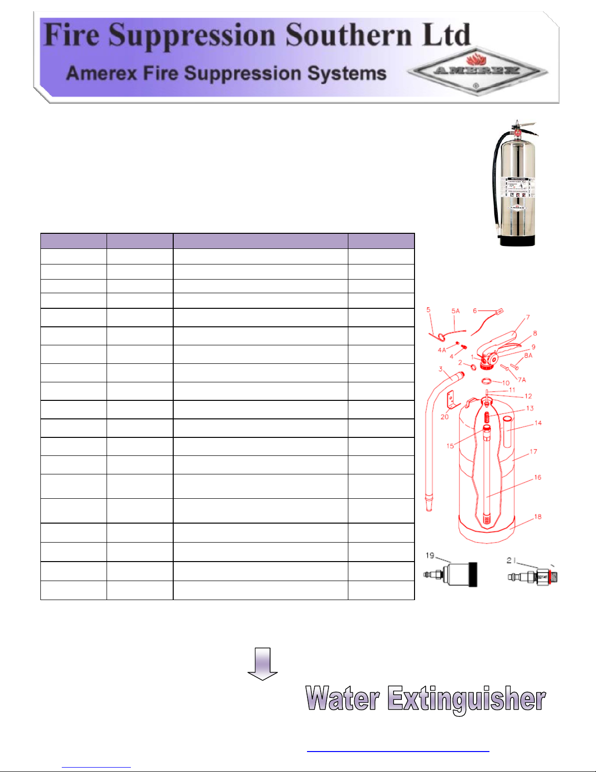
PARTS LIST
FOR
2 ½ GALLON STAINLESS STEEL STORED PRESSURE
WATER EXTINGUISHER
(BRASS VALVE)
MODEL 240
ITEM NO.: PART NO.: DESCRIPTION STD. PKG.
1 13281
V
alve Assembly - 240
2 06978 Hose Gasket (O-Ring)
4 00155 Pressure Vlv and Cap Ass’y –240 onl
y
4A 00158 Cap only for Pressure Vlv –240 only
5 00160 Ring Pin, Stainless Steel
5A 00532 Chain (Nylon) for Ring Pin
6 01387 Lock Wire Seal (Yellow)
7 07762 Lever & Rivet
7A 01563 Rivet Only for Lever
8 09020 Handle & Rivets
8A 01564 Rivet Only for Handle (2 required)
9 01564 Gauge 100 psi (Stainless Steel Tube)
10 05240
Collar O-ring
Collar O-ring (Bulk Bag)
11 05240
Valve Stem Assembly
Valve Stem Assembly (Bulk Bag)
12 05243
V
alve Stem O-Ring
13 00383 Spring
14 02595 Fill Tube
12O-Ring-Downtube/Retainer05690 15
1
6
24
6
96
24
100
1
24
1
24
1
500
24
24
1
1
24
1
PARTS LIST CONTINUED
Page 7 of 8
Unit D4 Seedbed Business Centre, Vanguard Way, Shoeburyness, Essex, SS3 9QY,
T: 01702 384038 F: 01702 384043 E: [email protected]
Page 8
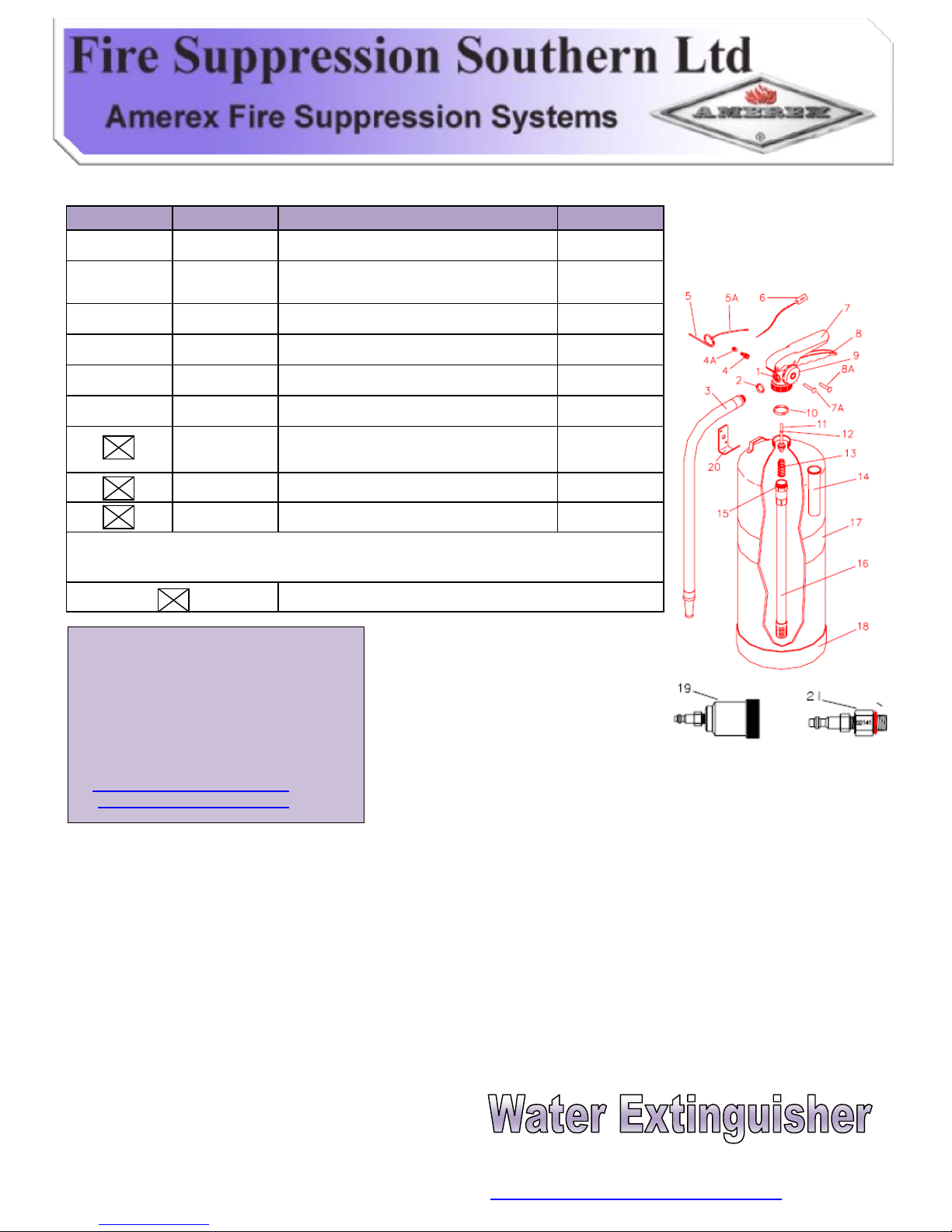
16 00404 Downtube/Retai ner Assembly - 240
ITEM NO.: PART NO.: DESCRIPTION STD. PKG.
17
Nameplate (label) non UL – SPECIFY MODEL
NO. OF EXTINGUISHER
18 02520 Footstand w/clip (Black) - 240
19 03181 Hydro test Adapter
20 01007 Wall Bracket
21 02141 Pressurizing Adapter
01928
Model – 506 Loaded Steam anti-freeze
charges – Model 240 Only
06247
V
isilox Lubricant (5 oz. Tube)
04488 Adhesive (Footstand) 3 oz. Tube
PART NOT PICTURED
NOTE: ALL VALVE ASSEMBLIES INCLUDE NEW VALVE BODY, GAUGE, KNURLED NUT, LEVER &
HANDLE AND PRESSURE VALVE
1
1
1
1
6
1
1
1
1
SteveMann
FireSuppressionSouthernLtd.
UnitD4SeedbedBusinessCentre
VanguardWay
Shoeburyness
Essex
SS39QY
T:01702384038
F:01702384043
E:
W:www.firesuppressionsouthern.com
Page 8 of 8
Unit D4 Seedbed Business Centre, Vanguard Way, Shoeburyness, Essex, SS3 9QY,
T: 01702 384038 F: 01702 384043 E: [email protected]
 Loading...