

ameco AC-1, AC-1T Service Manual
INSTRUCTIONS FOR AMECO TRANSMITTER KIT,
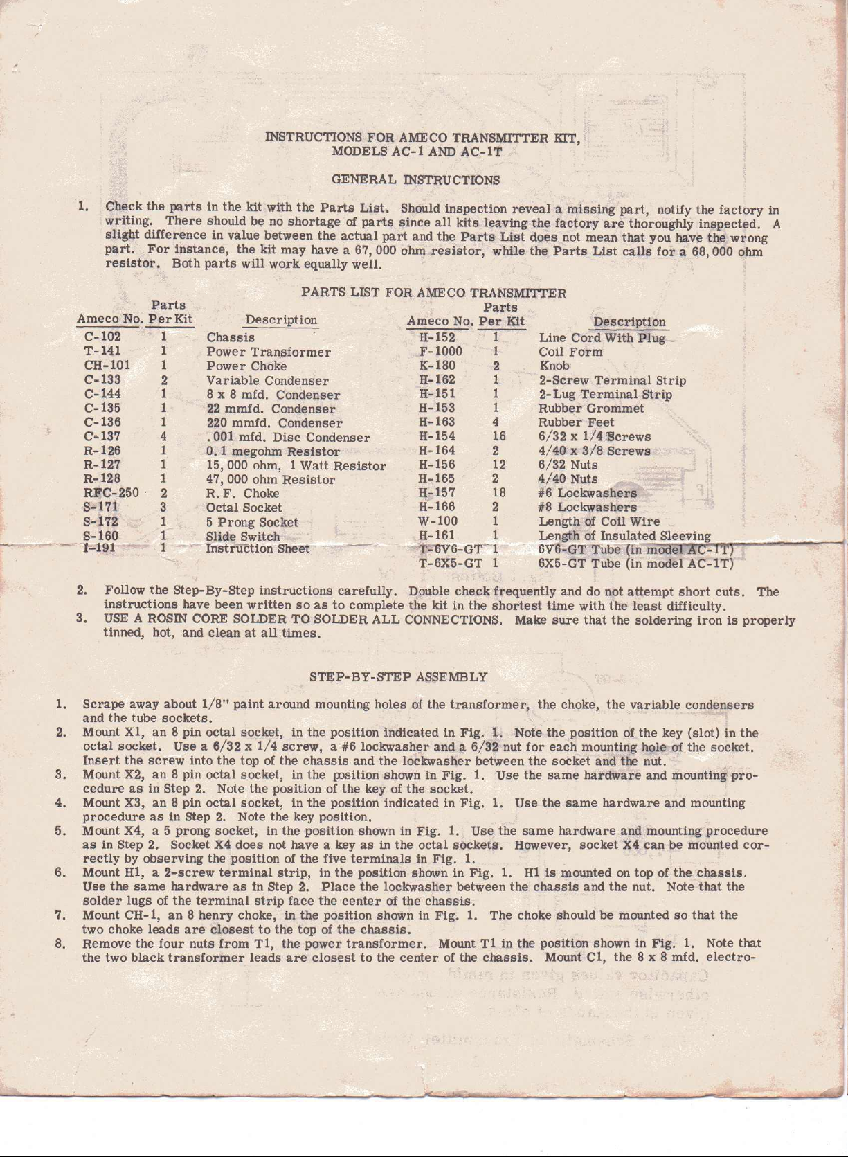
1. Check the parts in the kit with the Parts List. Should inspection reveal a missing part, notify the factory in
writing. There should be no shortage of parts since all kits leaving the factory are thoroughly inspected. A
slight difference in value between the actual part and the Parts List does not mean that you have the wrong
part. For instance, the kit may have a 67,000 ohm resistor, while the Parts List calls for a 68,000 ohm
resistor. Both parts will work equally well.
MODELS
GENERAL INSTRUCTIONS
AC-l
AND AC-IT
Parts
Ameco No. Per Kit
C-I02
T-141
CH-I01
C-133
C-144
C-135
C-136
C..
137
R-126
R-127
R-128
RFC-250'
S-I71
S-172
8-160
----1-191
2. Follow the step-By-Step instructions carefully. Double check frequently and do not attempt short cuts. The
instructions have been written so as to complete the kit in the shortest time with the least difficulty.
3. USE A ROSIN CORE SOLDER TO SOLDER ALL CONNECTIONS. Make sure that the soldering iron is properly
tinned, hot, and clean at all times.
1.
1 Power Transformer
1 Power Choke
2 Variable Condenser
1 Sx8 mfd. Condenser
1 22 mmfd. Condenser
1 220 mmfd. Condenser
4 . 001 mfd. Disc Condenser
1 0.1 megohm Resistor
i
1 47, 000 ohm Resistor
2 R. F. Choke
3 Octal Socket
1
1
1 -
Description
Chassis
15, 000 ohm, 1 Watt Resistor
5
Prong Socket
Slige Switch
InstrUCtion-Sheet
PARTS LIST FOR AMECO TRANSMITTER
Parts
Ameco No. Per Kit
H-152 1
F-lOOO 1
K-180 2
H-162 1
H-151 1
H-153 1
H-163
H-154 16
H-164 2
H-156 12
H-165 2
a-157 18
H-166
W-100 1
H-161 1
T=OV'6-Grl
T-6X5-GT 1
STEP-BY-STEP ASSEMBLY
4
2
Line Cord With Plug _
Coil Form
Knob:
2-Screw Terminal Strip
2-Lug Terminal Strip
Rubber Grommet
Rubber Feet
6/32x1/4iScrews
4/40x3/S Screws
6/32 Nuts
4/40 Nuts
#6 Lockwashers
#S Lockwashers
Length of Coil Wire
Length of Insulat_,;;.e.;;;:d..:S:.;le::..e;;..v;.;i.:;ng~.....
6V'6-GT Tube In mo e
6X5-GT Tube (in model AC-IT)
Description
-.-'"""i
1. Scrape away about l/S" paint around mounting holes of the transformer, the choke, the variable condensers
and the tube sockets.
2. Mount Xl, an 8 pin octal socket, in the posttion indicated in Fig.
octal socket. Use a 6/32 x 1/4 screw, a #6 Iockwasher and a 6/32 nut for each mounting hole---ofthe socket.
Insert the screw into the top of the chassis and the lockwasher between the socket and the nut.
a.
Mount X2, an S pin octal socket, in the posttion shown in Fig.
cedure as InStep 2. Note the position of the key of the socket.
4. Mount
5. MoUntX4, a 5 prong socket, in the position shown in Fig.
as in Step 2. Socket X4 does not have a key as in the octal sockets. However, socket X4 can be mounted cor-
6. Mount HI, a 2-screw terminal strip, in the
7. Mount CH-l, an 8 henry choke, in the position shown in Fig.
two choke leads are closest to the top of the chassis.
8. Remove the four nuts fr.om TI, the power transformer. Mount Tl in the position shown in Fig. 1. Note that
the two black transformer leads are closest to the center of the chassis. Mount CI, the 8 x 8 mfd. electro-
xa,
an 8 pin octal socket, in the position indicated in Fig.
procedure as in step 2. Note the key
posttton,
1.
rectly by observing the posttion of the five terminals in Fig. 1.
posrtton
Use the same hardware as in Step 2. Place the lockwasher between the chassis and the nut. Note that the
solder lugs of the terminal strip face the center of the chassis.
shown in Fig.
1.
Note the position of the key (slot) in the
1.
Use the same hardware and mounting pro-
1.
Use the same hardware and mounting
Use the same hardware and mounting procedure
1.
HI is mounted on top of the chassis.
1.
The choke should be mounted so that the
-
.
'
~
-,
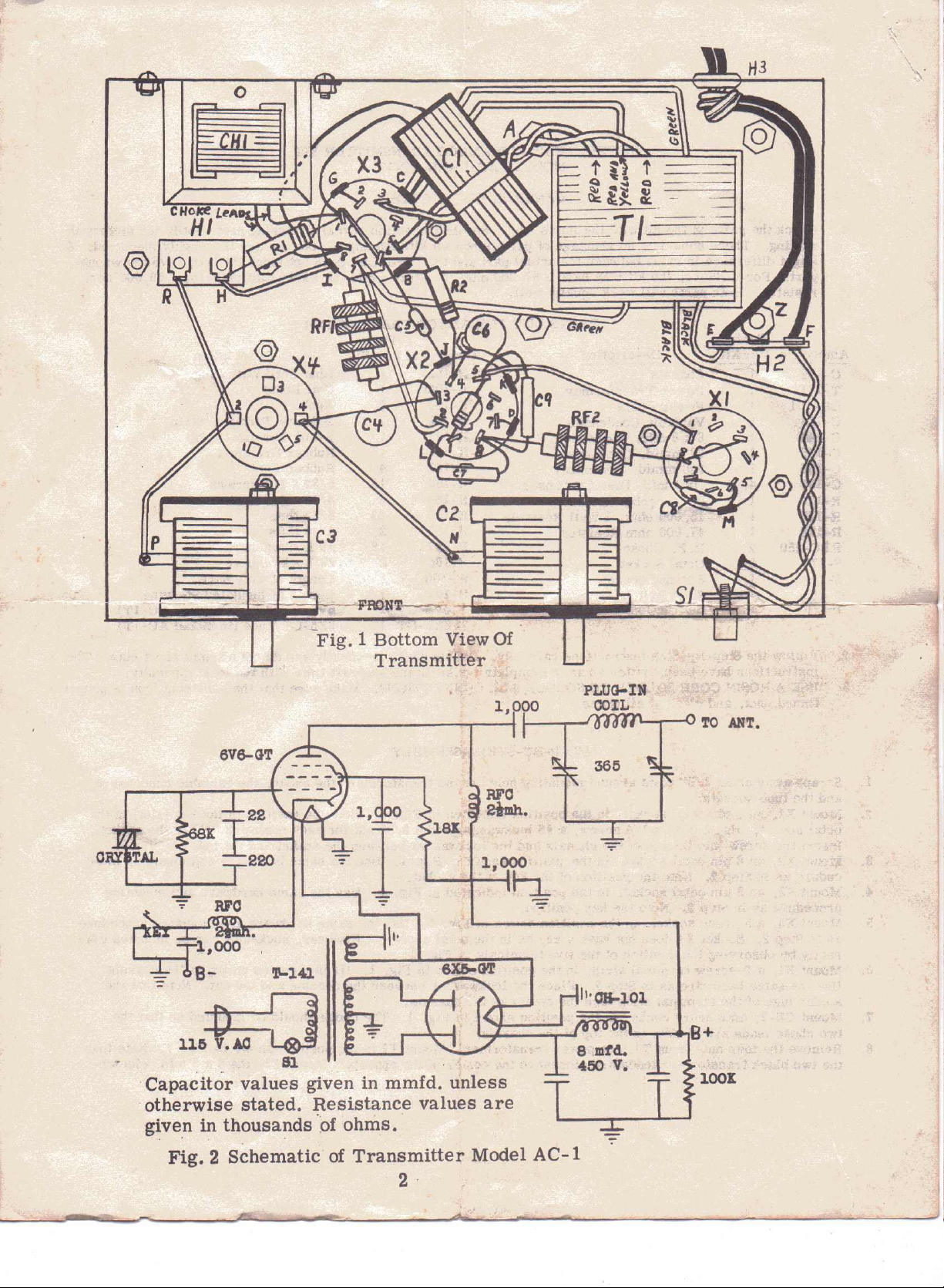
-Fig. 1 Bottom ViewOf '
Transmitter
.
,
r~l,OOO' "
~B- 1\-141
llD~
.
81
"
,Capacitor values given in mmfd. unless
'otherwise stated. Resistance values are
given in thousands
'.of
ohms.
366
lOOK
Fig. 2 Schematic of Transmitter Model
2,
AC-l
 Loading...