

Page 1

WHITE PAPER
Advanced Interconnect Standards
Blend Serial and Parallel Techniques
for Best Performance and Scalability
Mario Cavalli
General Manager
HyperTransport Consortium
Executive Summary
As modern computer architectures have pushed processor clock frequencies to 4 GHz, advanced
I/O link technologies have embraced a number of new technologies and approaches to enable I/O
data streams to keep up with processor speeds. It has become commonplace in the industry to think
that parallel buses are old, slow and limited in bandwidth, and serial buses are newer, faster and
enable higher bandwidth capabilities. But a new breed of interconnect technologies featuring the
best of both serial and parallel bus features have emerged. This paper compares and contrasts
serial and parallel bus characteristics and describes how these characteristics have come together
in the HyperTransport and PCI Express interconnects.
Comparing Parallel and Serial Bus Characteristics
In the past, common on-board computer bus architectures were purely parallel and off-board
communication links were more often serial, better suited for signal shielding and long haul data
transmission. The PCI (Peripheral Component Interconnect) bus, for example – a widely used onboard I/O bus – is parallel while Ethernet – a widely used system-to-system communication I/O
technology – is serial.
With the emergence of advanced, high-speed I/O interconnects such as HyperTransport and PCI
Express, a blending of parallel bus and serial bus characteristics has occurred. Such blending of
capabilities and features has become increasingly necessary to deliver the desired balance of performance, ease of system design, signal integrity and cost of application-specific implementations.
Therefore, today’s advanced I/O architectures have borrowed many characteristics from serial
technologies, but have also retained several features that draw from the efficiency of parallel architectures. The distinction between parallel and serial buses is detailed in Table 1 and Figure 1 below.
HyperTransport - White Paper June 22, 2007 www.HyperTransport.org
Page 2
Page 2
Parallel Serial
Clocking
Data Encapsulation
Signal Technology
Number of Lanes
Byte or Bit Lanes
Sideband Signals
Master Clock Clock-Data Recovery
Function per wire Packets
Single-ended Signaling
Single lane Multiple lanes
Bit lane Byte Lane
Yes No
Optical or Differential signaling
with Tx and Rx Equalization
Table 1: Parallel vs. Serial Bus Characteristics
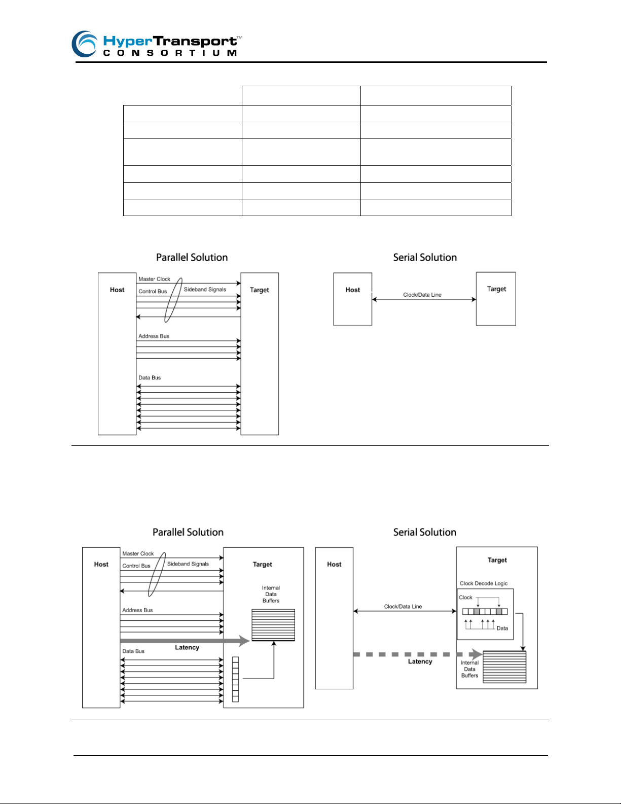
Figure 1: Parallel vs. Serial Clock Implementation
Figure 1 shows that parallel solutions require a master clock to synchronize all system-level activity between devices. The clocks and control signals (read/write, address/data, interrupts, acknowledge) are
called sideband signals. Serial links combine clock signals and data signals onto a single line or pair.
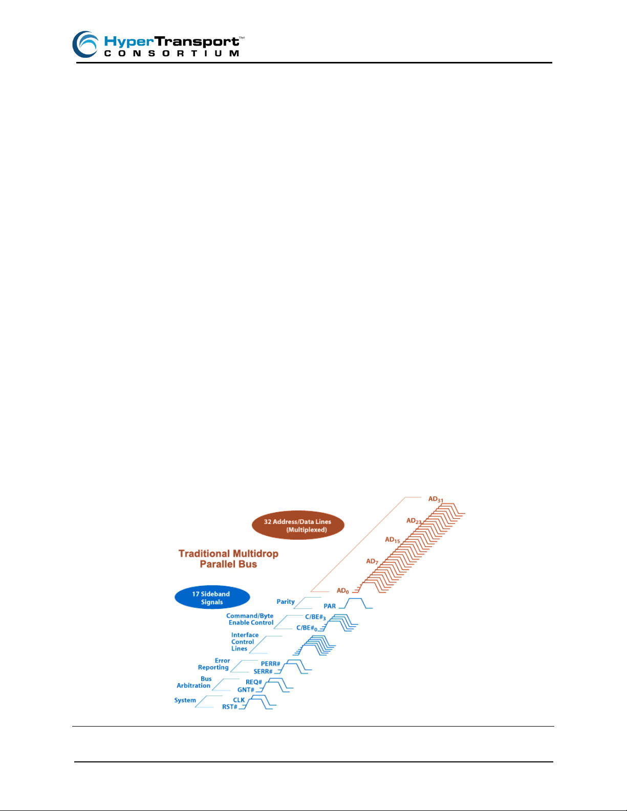
Figure 2: Parallel vs. Serial Clock Latency
HyperTransport - White Paper June 22, 2007 www.HyperTransport.org
Page 3
Page 3
Figure 2 shows that serial solutions require clock/data encoding and decoding logic in each device
that increases device complexity, adds latency and decreases usable bandwidth.
The key differences between parallel and serial interconnects are clock characteristics, the number
of signal lines, data encapsulation, and the number of sideband signals. For the system designer,
the important functional characteristics of any I/O interface are bandwidth (how much data can be
carried across the link), latency (how long does it take for data to arrive from source to destination)
and design complexity (how difficult is it to deliver bandwidth where it is needed).
For traditional parallel approaches, as processor clock speeds increase and data transfers increase,
the penalty factors are limited bandwidth using existing parallel bus technologies and increasing
design complexity at higher speeds. For serial approaches the penalty factors have always been
clock decode/encode overhead, packet encapsulation overhead, and latency issues.
In developing advanced I/O interconnect architectures like HyperTransport technology and PCI
Express, these limitations have been overcome by using a blend of parallel and serial
characteristics. Understanding the tradeoffs made by each approach will help the system designer
decide the usefulness of each technology for a given application.
Purely Parallel – PCI
The Peripheral Component Interconnect (PCI) bus supplanted a number of custom and semiproprietary buses during the 1990s, finding wide use in systems ranging from PCs, servers and even
embedded systems. In similar fashion to the proprietary processor buses it has supplanted, PCI is a
shared, parallel multi-drop bus with multiplexed address and data signals along with a number of
control signals. Unlike processor buses, PCI was designed to support board-to-board communications as well as chip-to-chip links and included along with 5-volt and later 3.3-volt signal drive
capabilities, a card slot expansion connector specification and board form factor definitions. PCI
supports a robust system initialization, discovery and setup. During initialization, the operating
system can discover all attached PCI compatible components, allocate resources and configure the
I/O devices according to their capabilities.
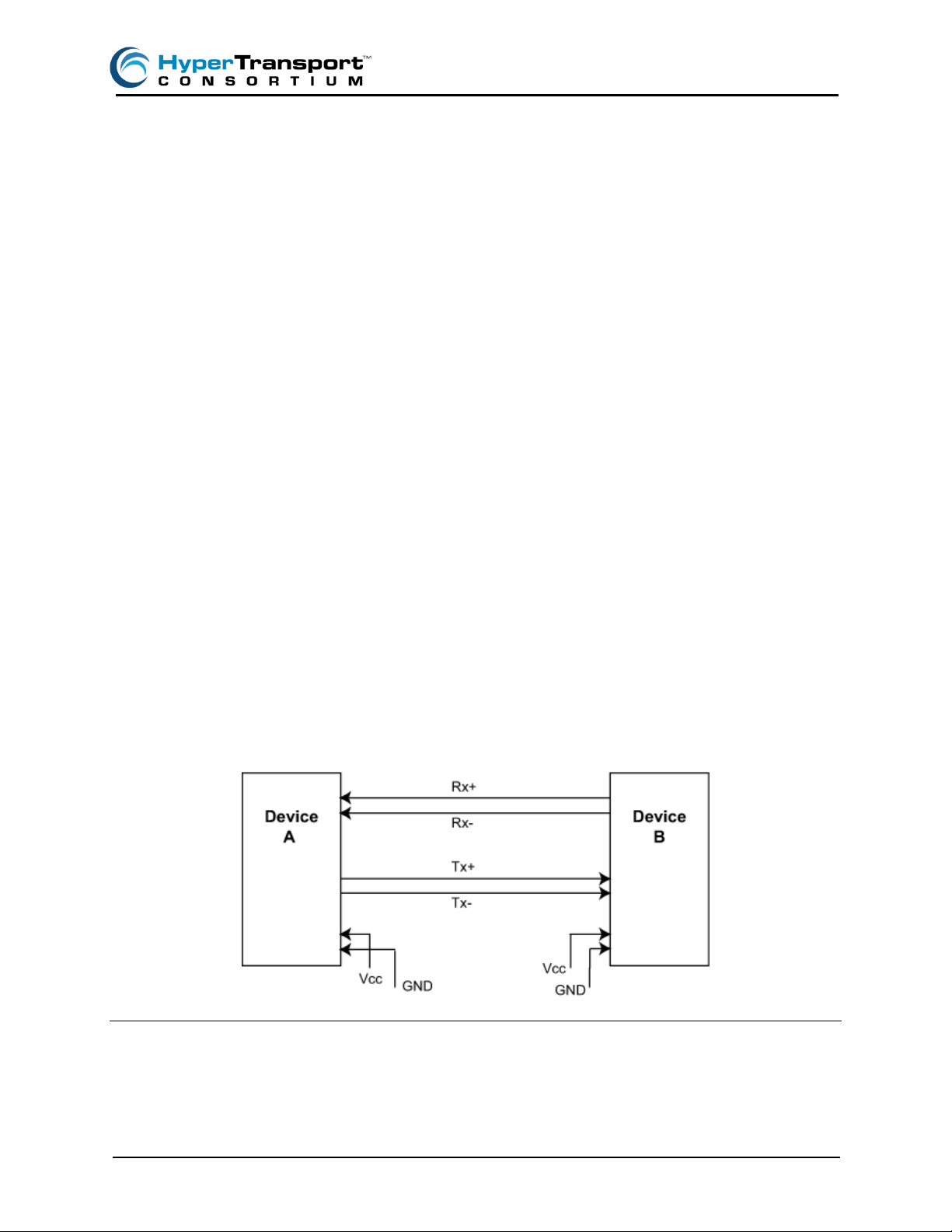
Figure 3: 32-bit Wide Parallel PCI Bus
HyperTransport - White Paper June 22, 2007 www.HyperTransport.org
Page 4
Page 4
PCI’s 66 MHz top clock speed falls far short of the Gigahertz and upward clock speeds of modern
processors, however, and attempts to squeeze higher speeds from PCI achieved limited results due
to signal integrity concerns of many parallel signals racing across large quantities of printed circuit
board real-estate.
In Figure 3, a 32-bit-wide parallel PCI bus is shown. It uses multiplexed address/data lines, numerous control lines and system-level signals. Many sideband signals are needed to track bus activity
on the multiplexed address/data lines and to provide system-level controls.
Because of its widespread use, the industry extended the PCI bus with the PCI-X specification that
boosted PCI bus speeds to 533 MHz and yielded a 4.3 Gigabytes/second bandwidth. To alleviate
signal routing limitations, PCI-X was changed to a point-to-point architecture versus PCI’s multidrop
architecture. Nonetheless, PCI-X is seen by most as just an interim solution to I/O communications
in modern systems due to bandwidth limits and design complexities. For example, to achieve the 4.3
GB/s bandwidth, clock speeds of 533 MHz must be attained and 64-bit wide data buses deployed.
This poses a challenge with today’s standard printed circuit board (PCB) design and manufacturing
technologies due to unwanted cross-coupling effects, impedance factors and consequent signal
integrity degradations exasperated by those many parallel lines.
In whatever format, the parallel bus delivers its data in one-bit-per-one-data-line form. With the entire
parallel data set clocked in with the master clock, the receiving device collects the data bits, ensures
that they fall within the specified timing sequence and then moves the data into its local data buffers.
The resulting data latency is low, as the entire data set arrives simultaneously with the master clock.
Purely Serial – Ethernet
By comparison, a purely serial I/O technology such as Ethernet uses just a few signal lines to carry
data packets that contain both control information and data. The signal-level complexity is much
lower – thus facilitating data transmission over long distances – although there is significant
overhead in clock encoding/decoding and packet processing before the data can be extracted from
the signal flow. This overhead results in much higher latency as well as increased transmit/receive
device complexity and power consumption.
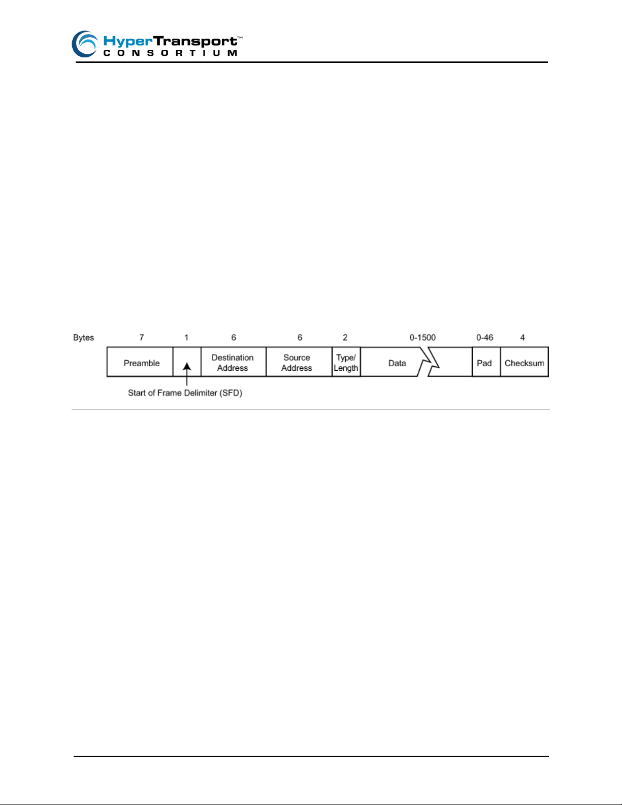
Figure 4: Ethernet Interface Signals
As Figure 4 shows, the serial 10/100Base-T Ethernet I/O technology uses four signal lines (Tx+, Tx-,
Rx+, Rx-) with one pair used for transmit operations and one pair for receive operations. The signal
HyperTransport - White Paper June 22, 2007 www.HyperTransport.org
Page 5
Page 5
is a differential electrical signal with each wire pair twisted in the cable for improved signal immunity.
As with any active electronic device, power and ground signals are needed for each device.
Since a single signal pair carries both data and clock information, this information must be first
encoded into the serial data stream and then decoded at the receiving end. Ethernet uses a variety
of encoding methods. High speed Gigabit and 10 Gigabit Ethernet standards use 8-bit/10-bit
(8B/10B) encoding techniques developed in the 1980s by IBM for use in high-speed FibreChannel
technology. In 8B/10b encoding, 8 bit data bytes are converted into 10 bit transmission characters.
Such an encoding pattern makes it easier to synchronize bits, simplifies the design of receivers and
transmitters, improves error detection and more easily supports the insertion of easily recognized
control characters into the data stream. However, the 2 extra bits of conversion impose a fixed 20%
overhead penalty that affects every control character (idle, start of packet, end of packet) and data
character sent over the interconnect link.
A key characteristic of Ethernet technology is the packet encoding. As shown in Figure 5, Ethernet
packets are comprised of up to 1500 bytes of data payload with additional fields that define various
system-level functions. These include source, destination, and checksum to ensure data integrity as
packets move across the network. Figure 5 shows the structure of the Ethernet packet and the byte
length of each field.
Figure 5: Ethernet Frame Structure
Ethernet packet encoding enables the transfer of any size, time-insensitive information across a
network topology. Packets may find their way from source to destination in a variety of paths or
routes and it is up to the receiving device to reassemble the packets in their right order. This makes
it easy for developers, as they have no need to understand or factor-in the network topology when
implementing an Ethernet device. However, it makes latency a major issue for system designers that
require a precise time window for delivery of data from one device to another.
While Ethernet has been extended with numerous additional tagging capabilities that facilitate
video streaming and other high-bandwidth, time sensitive data streams, it is not suitable for highperformance, on-board point-to-point communications.
Parallel and Serial Blends – HyperTransport and PCI Express
To address the I/O bandwidth issues posed by processors operating at or above 1 GHz, two basic
camps emerged during the late 1990s. The developers of the HyperTransport interconnect
technology addressed the issues of high bandwidth with a focus on the problems that high-speed
processor based systems faced and the I/O bottleneck posed by PCI-type buses.
A key goal was to maintain a very low point-to-point communication latency. This was a result of
HyperTransport’s processor-centric, or otherwise defined as processor–native) architecture and
the recognition that in any high performance processor-based system, data transfers between
processors, between processor and high-speed memory, or between processor and high-speed I/O
subsystems, latency is always an important and often the most important performance factor. That
HyperTransport - White Paper June 22, 2007 www.HyperTransport.org
Page 6

Page 6
realization, coupled with a desire to preserve software-level PCI compatibility, resulted in the
creation and standardization of the HyperTransport I/O link technology specification as well as the
founding of the HyperTransport Consortium, the industry body that is responsible for licensing,
managing and promoting the HyperTransport standard industry wide.
The creators of PCI Express focused on developing an interconnect standard that could incorporate
device-to-device, subsystem-to-subsystem and even system-to-system communications. The latter
effort eventually evolved into the ASI Advanced Switching Interconnect standard (also called PCI
Express Advanced Switching). As an omnibus standard, PCI Express defined not only device-todevice communications but included a detailed slot-based architecture as well. Consequently, the
standard is far more complex and anticipates a much wider set of slot-based implementations than
HyperTransport technology does.
In general, PCI Express constitutes an evolutionary step to PCI and PCI-X and therefore best suited
for general purpose slot-based, peripheral subsystems, while HyperTransport is the ideal interconnect solution for processor-to-processor and processor-to-high performance subsystems links
that require high bandwidth and very low latency capability. For HyperTransport-based board-toboard interconnects, the HyperTransport HTX™ Expansion Specification – standardized by the
HyperTransport Consortium – defines a motherboard/daughter slot connector specification that
enables fast, low latency, direct-connect HyperTransport links between system processor(s) and
high-performance subsystems. While HTX™ and PCI Express may seem to overlap in such kind of
applications, HTX deliver the extra low latency sought by server cluster interconnects, co-processing
modules and high-performance peripheral subsystems that PCI Express is unable to support.
Both HyperTransport and PCI Express have been well accepted in the industry and complement
each other by delivering their respective best in a number of latest generation high-performance
system designs.
It is useful to understand the difference in how the two technologies combine parallel and serial characteristics to achieve their intended objectives. The table below shows the two technologies compared to the purely parallel (PCI) and purely serial (Ethernet) solutions; color coding shows which
strengths of the parallel and serial camps they draw from to best serve their target applications.
Clocking
Data
Encapsulation
Signal
Technology
Number of Lanes
Byte or Bit Lanes
Sideband Signals
Purely
Parallel (PCI) HyperTransport PCI Express
Master Clock
Function per
wire
Single-ended
Signaling
Multiple Lane Multiple Lane Multiple Lane Single Lane
Bit Lane Bit Lane Byte Lane Byte Lane
Yes Yes Yes No
Source
Synchronous
Packets Packets Packets
Differential
Signaling with
Tx EQ
Data Recovery
Differential
Signaling with
Tx EQ
Purely Serial
(Ethernet)
Clock-Data
Recovery
Optical or Differential
signaling with
TX & Rx EQ
Table 2: HyperTransport and PCI Express vs. Purely Parallel and Serial Buses
HyperTransport - White Paper June 22, 2007 www.HyperTransport.org
Page 7
Page 7
HyperTransport Technology Details
A point-to-point interconnect like HyperTransport has many advantages over shared bus structures.
It needs far fewer sideband signals because its enhanced 1.2V LVDS signals are not multiplexed,
use less power, exhibit better noise immunity and require no passive filtering. The electrical characteristics of the link are simplified and enable much faster clock speeds and correspondingly
greater bandwidth as compared to parallel buses. LVDS links use two wire lines per each signal line
– otherwise called balanced, or differential line – carrying electrical signals that are equal in amplitude and timing but with opposite polarity.
The specular nature of the signals carried over the balance line prevents electrical noise within the
system from affecting and potentially corrupting the signal detection process at the receiver end –
typical problems of single-ended signaling in high-speed parallel buses – thus allowing for much
cleaner signal transmission and higher clock rates. LVDS signaling consumes less power and
delivers a more robust signal that requires no passive components to maintain signal integrity. Even
with the use of two wires per signal, the faster, narrower HyperTransport link uses fewer total
signals, consumes less power (thanks to fewer sideband signals and no always-on clock encoding
circuitry), and delivers higher bandwidth at a lower overall system cost than traditional parallel
multiplexed buses.
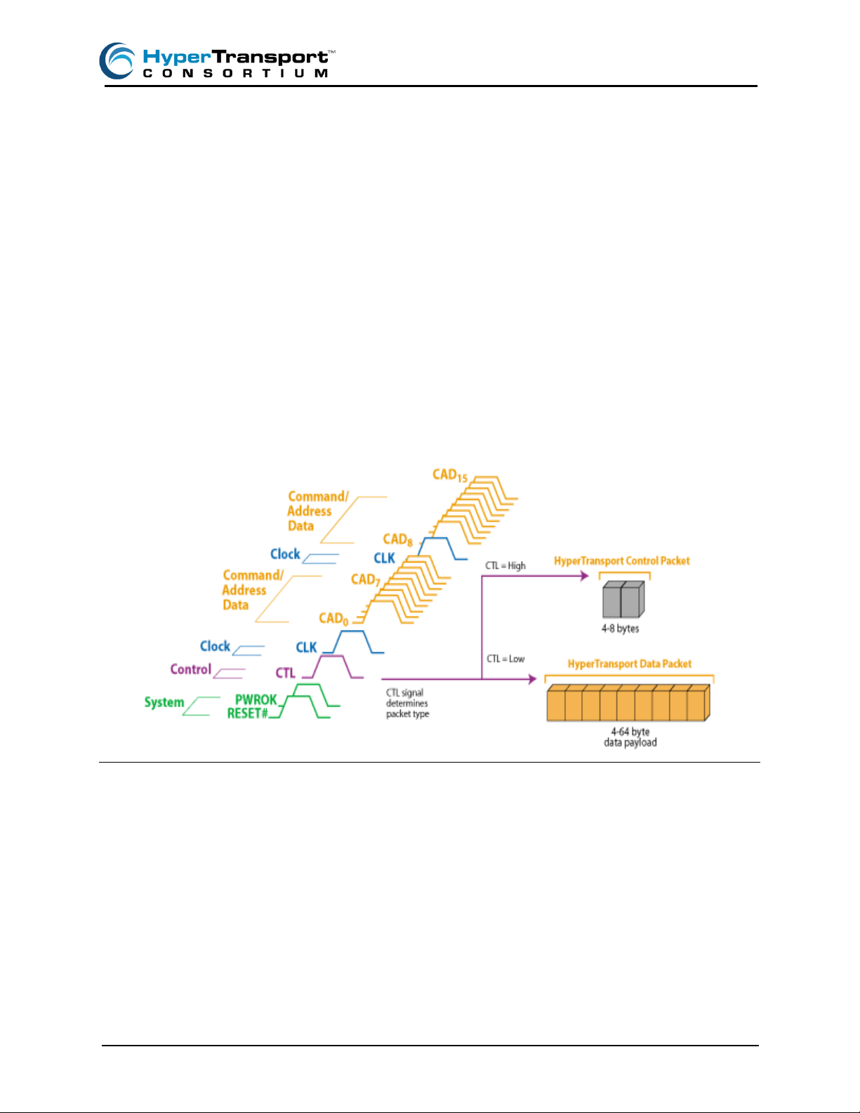
Figure 6: 16-bit HyperTransport Link
Figure 6 shows a point-to-point bus such as HyperTransport (16-bit wide link shown), which reduces
the number of signals required by combining command, address and data information into
HyperTransport packets that are carried in a single direction over CAD (Command, Address, Data)
lines. The simplified control structure needs only 5 sideband signals.
PCI Express Technology Details
PCI Express, like HyperTransport, is a point-to-point link that uses dual unidirectional lanes to
connect devices. Unlike HyperTransport, the link uses lanes that carry clock, command, data, and
address information and can be scaled from x1 to x32. This burdens the interface with the extensive
overhead of serial/deserializers and 8B/10B clock encoding/decoding logic.
HyperTransport - White Paper June 22, 2007 www.HyperTransport.org
Page 8
Page 8
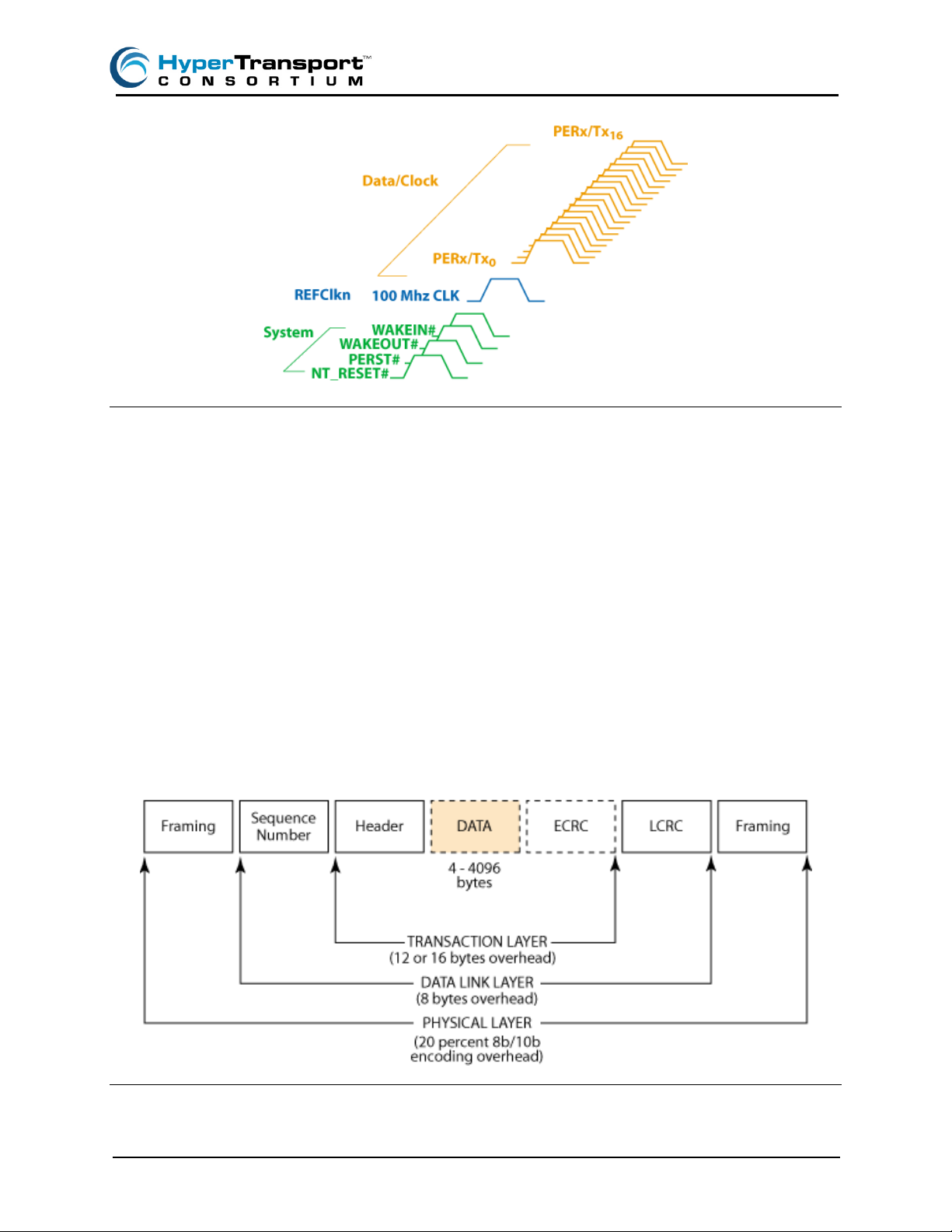
Figure 7: 16x PCI Express Lane Signal Set
While the clock recovery circuitry is well proven, it takes additional chip real estate and consume
much power, as it is constantly monitoring the receive signal flow for meaningful signals. In addition
to the data/control lanes, PCI Express requires a number of additional sideband signals regardless
of how many or how few Data/Clock lanes are implemented. These include two resets, wake in/out
and a 100 MHz reference clock as shown in Figure 7.
The point-to-point PCI Express link, as shown in Figure 7, also requires five sideband signals
including a 100 MHz reference clock and system signals for wake in/out and two reset signals,
equaling the number of signals carried by a 16-bit HyperTransport link. The primary data lane
(shown here in 16x wide format) carries the data and clock encoding. Like HyperTransport, PCI
Express uses LVDS signaling that requires two signal lines per data bit.
PCI Express management data is contained in the Data Link Layer Packet, or DLLP and payload
data is contained in a Transaction Layer Packet, or TLP. DDLP and TLP packets are interspersed in
a PCI Express data stream. Within the DDLP are the traditional PCI functions and the new PCI
Express functions like flow control and packet acknowledgements.
Figure 8: PCI Express Packet Format
HyperTransport - White Paper June 22, 2007 www.HyperTransport.org
Page 9
Page 9
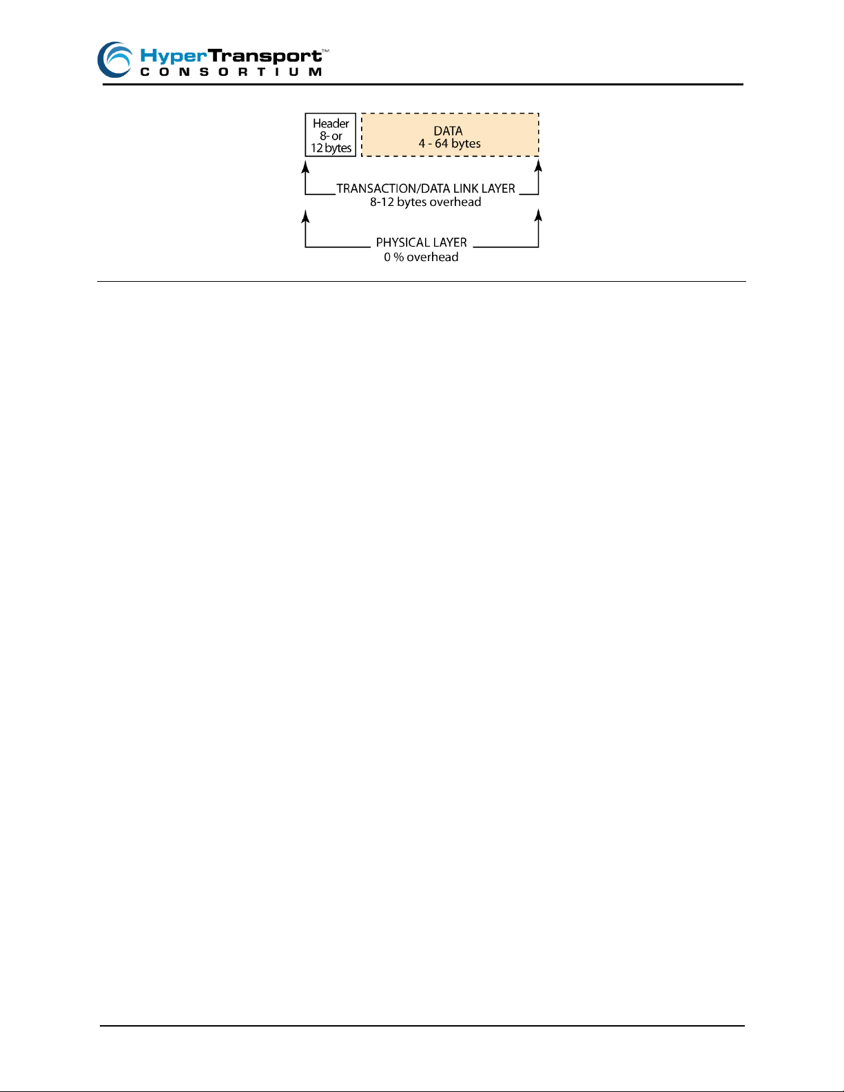
Figure 9: HyperTransport Packet Format
Figure 8 and 9 show PCI Express and HyperTransport packet formats. The PCI Express specification defines three layers, the Transaction, the Data Link and the Physical. The figure shows the overhead required for each layer in bytes. Packet overhead carries significant latency penalty for data
packets smaller than 64 bytes. While PCI Express supports large packet sizes – up to 4096 bytes –
this can also affect system throughput, as PCI Express has no mechanism for interrupting long
packet transfers. The HyperTransport packet format is much leaner, with only the header overhead.
The data payload in PCI Express is carried in the Transaction Layer Protocol or TLP packet. In
addition to the data, the TLP has a header of 12 or 16 bytes that hold information such as packet
size, message type, traffic class for QoS and any special handling instructions. The TLP is
concluded with a CRC coding for data integrity.
Summary
Both PCI Express and HyperTransport I/O technologies overcome the limitations of older parallel,
processor-centric bus structures such as PCI by leveraging the benefits of advanced serial I/O technology with some of the best characteristics of parallel I/O technologies. The blend of parallel and
serial techniques enables the delivery of very high bandwidth I/O solutions with tradeoffs between
low latency, device complexity and implementation that are tailored for their specific applications.
HyperTransport uses serial technology in its CAD (command, address, data) lines combined
with parallel-like, source synchronous, clock forwarding capability for lowest possible latency.
PCI Express uses serial technology in its 1x, 4x and 16x wide lanes that incorporates both the
primary clock as well as the data/address information. Both technologies require parallel-like
sideband signals, but far fewer than conventional parallel buses. Both utilize low voltage differential
signaling, and both require more signal lines than pure serial technologies such as Ethernet. Like
Ethernet, both use packet encapsulation and provide for error detection. In line with its general
purpose, peripheral I/O applications, PCI Express provides a more extensive error detection and
correction mechanism and further defines additional slot-based architecture signals and features.
HyperTransport includes an HTX HyperTransport Expansion slot connector definition to extend the
HyperTransport bus to a reduced spectrum of specialized high-performance, add-in subsystems.
HyperTransport delivers the lowest possible latency with its low packet overhead and unique
features such as Priority Request Interleaving for efficient peripheral interrupt processing that
support high-priority data traffic across the interconnect.
HyperTransport replaces the overlapping processor and local I/O buses of earlier generation systems with a unified, high bandwidth, low latency, and low-cost system interconnect architecture that
is scalable, low-cost and extensible to future product generations. The widespread adoption of
HyperTransport - White Paper June 22, 2007 www.HyperTransport.org
Page 10

Page 10
HyperTransport across a broad spectrum of high performance product sectors ranging from consumer devices to personal computers, workstations, network equipment, servers, high performance
computing platforms and supercomputers, is tangible proof of the top performance emphasis and
flexibility of the HyperTransport architecture. PCI Express has seen its adoption rate maximized as
graphics and I/O peripherals interconnect standard.
In conclusion, it is fair to say that the latest generation of advanced I/O technologies carries a
precisely chosen blend of parallel and serial technologies that deliver high bandwidth, high-speed
operation and low latency – each tailored to deliver the best balance of features and capabilities for
their intended applications – and are proving viable, scalable building block technologies to serve
high-performance applications and requirements for years to come.
For more information on HyperTransport technology, please refer to additional white papers available at www.hypertransport.org
.
HyperTransport is a licensed trademark of the HyperTransport Technology Consortium. All other trademarks belong to their respective
owners.
HyperTransport - White Paper June 22, 2007 www.HyperTransport.org
 Loading...