


PRELIMINARY
Am29BDS323D
32 Megabit (2 M x 16-Bit)
CMOS 1.8 Volt-only Simultane ous Read/Write, Burst Mode Flash Memory
DISTINCTIVE CHARACTERISTICS
■ Single 1.8 volt read, program and erase (1.7 to
1.9 volt)
■ Multiplexed Data and Address for reduced I/O
count
— A0–A15 multiplexed as D0–D15
— Addresses are latched with A VD# control inputs
while CE# low
■ Simultaneous Read/Write operation
— Data can be continuously read from one bank
while exec uting erase/progr am functions in othe r
bank
— Zero latency between read and write operations
■ Read access times at 40 MHz
— Burst access times of 20 ns @ 30 pF
at industrial temperature range
— Asynchronous random access times
of 110 ns @ 30 pF
— Synchronous random access times
of 120 ns @ 30 pF
■ Burst length
— Continuous linear burst
■ Power dissipation (typical values, 8 bits
switching, C
— Burst Mode Read: 25 mA
— Simu ltan eous Operation: 40 mA
— Program/Erase: 15 mA
— Standby mode: 0.2 µA
■ Sector Architecture
— Eight 4 Kword sectors and sixty-three sectors of
32 Kwords each
— Bank A contains the eight 4 Kword sectors and
fifteen 32 Kword sectors
— Bank B contains forty-eight 32 Kword sectors
= 30 pF)
L
■ Sector Protection
— Software command sector locking
— WP# protects the last two boot sectors
— All sectors locked when V
■ Software command set compatible with JEDEC
42.4 standards
— Backwards compatible with Am29F and Am29LV
families
■ Minimum 1 million erase cycle guarantee
per sector
■ 20-year data retention at 125°C
— Reliable operation for the life of the system
■ Embedded Algorithms
— Embedded Erase algorithm automatically
preprograms and erases the entire chip or any
combination of designated sectors
— Embedded Program algorithm automatically
writes and verifies data at specified addresses
■ Data# Polling and toggle bits
— Provides a software method of detecting
program and erase operation completion
■ Erase Suspend/Resume
— Suspends an erase operation to read data from,
or program data to, a sector that is not being
erased, then resumes the erase operation
■ Hardware reset input (RESET#)
— Hardware method to reset the device for reading
array data
■ CMOS compatible inputs, CMOS compatible
outputs
■ Low V
■ Package Option
— 47-ball FBGA
write inhibit
CC
PP
= V
IL
This Data Sheet states AMD’s current technical specifications regarding the Product described herein. This Data
Sheet may be revised by subsequent versions or modifications due to changes in technical specifications.
Refer to AMD’s Website (www.amd.com) for the latest information.
Publication# 23476 Rev: B Amendment/+4
Issue Date: September 4, 2001
PRELIMINARY
GENERAL DESCRIPTION
The Am29BDS323 is a 3 2 Mbit , 1. 8 Volt-only, simultaneous Read/Write, Burst Mode Flash memory de vice,
organized as 2,097,152 words of 16 bits each. This
device uses a single V
gram, and erase the memory array. A 12.0-volt V
of 1.7 to 1.9 V to read, pro-
CC
PP
may be used for faster program performance if desired.
The device can also be programmed i n standard
EPROM programmers.
The Am29BDS323 provides a burst access of 20 ns at
30 pF with initial acc ess time s of 120 ns at 30 p F. The
device operates within the industrial temperature range
of –40°C to +85°C. The device is offered i n the 47 -b all
FBGA package.
Simultaneous Read/Write Ope rations with
Zero Latency
The Simultaneous Read/Write architecture provides
simultaneous operation by dividing the memory
space into two banks. The device can improve overall
system performance b y a llowi ng a hos t s yste m to program or erase in one ba nk, then imme diately and s imultaneously read from the other bank, with zero
latency. This releases the system from waiting for the
completion of program or erase operations.
The device is divided as shown in the following table:
Bank A Sectors Bank B Sectors
Quantity Size Quantity Size
8 4 Kwords
15 32 Kwords
8 Mbits total 24 Mbits total
The device uses Chip Enable (CE#), Write Enable
(WE#), Address Valid (AVD#) and Output Enable
(OE#) to control asynchronous read and write operations. For burst operations, the device additionally
48 32 Kwords
requires Power Savi ng (PS), Rea dy (RDY) , and Clo ck
(CLK). This implementa tion allow s easy interfac e with
minimal glue log ic to a wide range of mic roprocessors/microcontrollers for high performance read operations.
The device offers complete compatibility with the
JEDEC 42.4 single-power-supply Flash command
set standard. Commands are written to the command
register using standard microprocessor write timings.
Reading data out of the device is similar to reading
from other Flash or EPROM devices.
The host system can detect whether a program or
erase operation is complete by using the device sta-
tus bit DQ7 (Data# Polling) and DQ 6/DQ2 (toggle
bits). After a program or erase cycle has been completed, the device automatically re turns to reading
array data.
The sector erase architecture allows memory sectors to be erased and reprogra mmed withou t affecting
the data contents of other sectors. The device is fully
erased when shipped from the factory.
Hardware data protection measures include a low
detector that automatically inhibits write opera-
V
CC
tions during power transitions. The device also offers
three types of data protection at the sector level. The
sector lock/unlock command sequence disabl es or
re-enables both program and erase operations in any
sector. When at V
tors. Finally, when V
, WP# locks the two outermost sec-
IL
is at VIL, all sectors are locked.
PP
The device offers two power-saving features. Whe n
addresses have been sta ble f or a spe cified am ount o f
time, the device enters the automatic sleep mode.
The system can also place the device into the
standby mode. Power consumption is greatly reduced in both modes.
2 Am29BDS323D

PRELIMINARY
TABLE OF CONTENTS
Product Selector Guide . . . . . . . . . . . . . . . . . . . . .4
Block Diagram . . . . . . . . . . . . . . . . . . . . . . . . . . . . 4
Simultaneous Op era tio n Circuit Block Diagram. 5
Connection Diagram . . . . . . . . . . . . . . . . . . . . . . . .6
Special Handling Instructions for FBGA Package ....................6
Input/Output Descriptions . . . . . . . . . . . . . . . . . . .7
Logic Symbol . . . . . . . . . . . . . . . . . . . . . . . . . . . . . 7
Ordering Information . . . . . . . . . . . . . . . . . . . . . . .8
Device Bus Operations . . . . . . . . . . . . . . . . . . . . . .9
Table 1. Device Bus Operations ......................................................9
Requirements for Asynchronous Read Operation(Non-Burst) 9
Requirements for Synchronous (Burst) Read Operation ..........9
Programmable Wait State ......................................................10
Power Saving Function ...........................................................10
Simultaneous Read/Write Operations with Zero Latency .......10
Writing Commands/Command Sequences ............................10
Accelerated Program Operation ......................................................11
Autoselect Functions .......................................................................11
Automatic Sleep Mode ...........................................................11
RESET#: Hardware Reset Input .............................................11
Output Disable Mode ..............................................................11
Hardware Data Protection ......................................................11
Low VCC Write Inhibit .....................................................................12
Write Pulse “Glitch” Protection ........................................................12
Logical Inhibit ..................................................................................12
Table 2. Sector Address Table ........................................................13
Command Definitions . . . . . . . . . . . . . . . . . . . . . .15
Reading Array Data ................................................................15
Set Wait State Command Sequence ......................................15
Table 3. Third Cycle Address/Data .................................................15
Enable PS (Power Saving) Mode Command Sequence ........15
Sector Lock/Unlock Command Sequence ..............................15
Reset Command .....................................................................15
Autoselect Command Sequence ............................................16
Program Command Sequence ...............................................16
Unlock Bypass Command Sequence ..............................................16
Figure 1. Program Operation .......................................................... 17
Chip Erase Command Sequence ...........................................17
Sector Erase Command Sequence ........................................17
Erase Suspend/Erase Resume Commands ...........................18
Figure 2. Erase Operation............................................................... 19
Command Definitions............................................................. 20
Table 4. Command Definitions .......................................................20
Write Operation Status . . . . . . . . . . . . . . . . . . . . .21
DQ7: Data# Polling .................................................................21
Figure 3. Data# Polling Algorithm ................................................... 21
DQ6: Toggle Bit I ....................................................................22
Figure 4. Toggle Bit Algorithm........................................................ 22
DQ2: Toggle Bit II ...................................................................23
Table 5. DQ6 and DQ2 Indications ................................................ 23
Reading Toggle Bits DQ6/DQ2 ...............................................23
DQ5: Exceeded Timing Limits ................................................23
DQ3: Sector Erase Timer .......................................................24
Table 6. Write Operation Status ..................................................... 24
Absolute Maximum Ratings . . . . . . . . . . . . . . . . 25
Figure 5. Maximum Negative Overshoot Waveform...................... 25
Figure 6. Maximum Positive Overshoot Waveform........................ 25
Operating Ranges. . . . . . . . . . . . . . . . . . . . . . . . . 25
DC Characteristics . . . . . . . . . . . . . . . . . . . . . . . . 26
Test Conditions . . . . . . . . . . . . . . . . . . . . . . . . . . 27
Figure 7. Test Setup....................................................................... 27
Table 7. Test Specifications ........................................................... 27
Figure 8. Input Waveforms and Measurement Levels ................... 27
AC Characteristics . . . . . . . . . . . . . . . . . . . . . . . . 28
Synchronous/Burst Read ........................................................28
Figure 9. Burst Mode Read............................................................ 28
Asynchronous Read ...............................................................29
Figure 10. Asynchronous Mode Read............................................ 29
Figure 11. Reset Timings............................................................... 30
Erase/Program Operations .....................................................31
Figure 12. Program Operation Timings.......................................... 32
Figure 13. Chip/Sector Erase Operations...................................... 33
Figure 14. Accelerated Unlock Bypass Programming Timing........ 34
Figure 15. Data# Polling Timings (During Embedded Algorithm) .. 35
Figure 16. Toggle Bit Timings (During Embedded Algorithm)........ 35
Figure 17. Latency with Boundary Crossing.................................. 36
Figure 18. Initial Access with Power Saving (PS)
Function and Address Boundary Latency...................................... 37
Figure 19. Initial Access with Address Boundary Latency............. 37
Figure 20. Example of Five Wait States Insertion.......................... 38
Figure 21. Back-to-Back Read/Write Cycle Timings...................... 39
Erase and Programming Performance . . . . . . . 40
Data Retention. . . . . . . . . . . . . . . . . . . . . . . . . . . . 40
Physical Dimensions* . . . . . . . . . . . . . . . . . . . . . 41
FDD047—47-Pin Fine-Pitch Ball Grid Array (FBGA)
7 x 10 mm package ................................................................ 41
Revision Summary . . . . . . . . . . . . . . . . . . . . . . . . 43
Revision A (February 15, 2000) ..............................................43
Revision B (June 20, 2000) ....................................................43
Revision B+1 (November 27, 2000) .......................................43
Revision B+2 (November 30, 2000) .......................................43
Revision B+3 (December 21, 2000) .......................................43
Revision B+4 (September 4, 2001) ........................................43
Am29BDS323D 3
PRODUCT SELECTOR GU IDE
PRELIMINARY
Am29BDS323D
Part Number
Max Initial Access Time, ns (t
= 1.7 – 1.9 V
V
CC
Max Burst Access Time, ns (t
Max OE# Access, ns (tOE) 20 Max OE# Access, ns (tOE)35
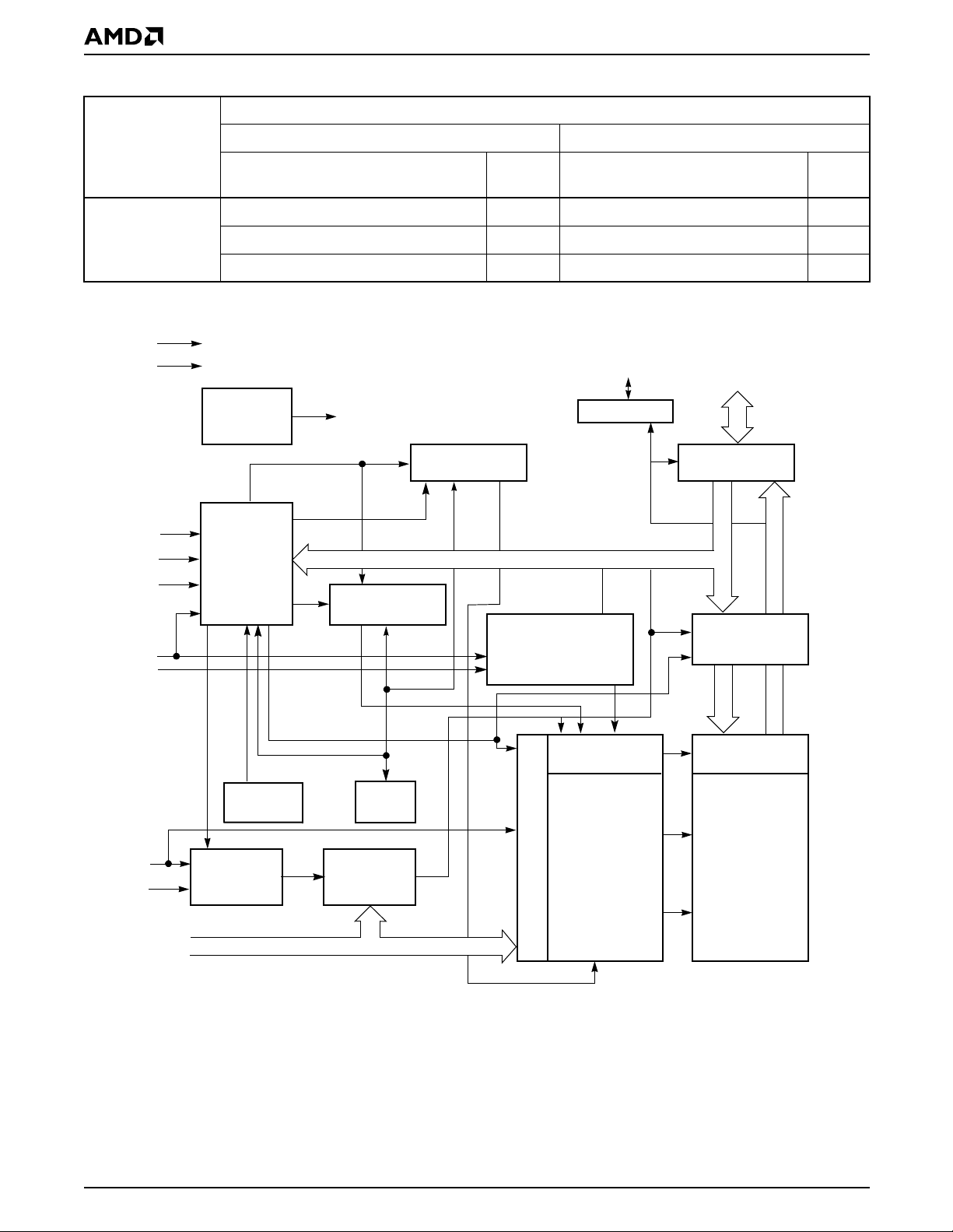
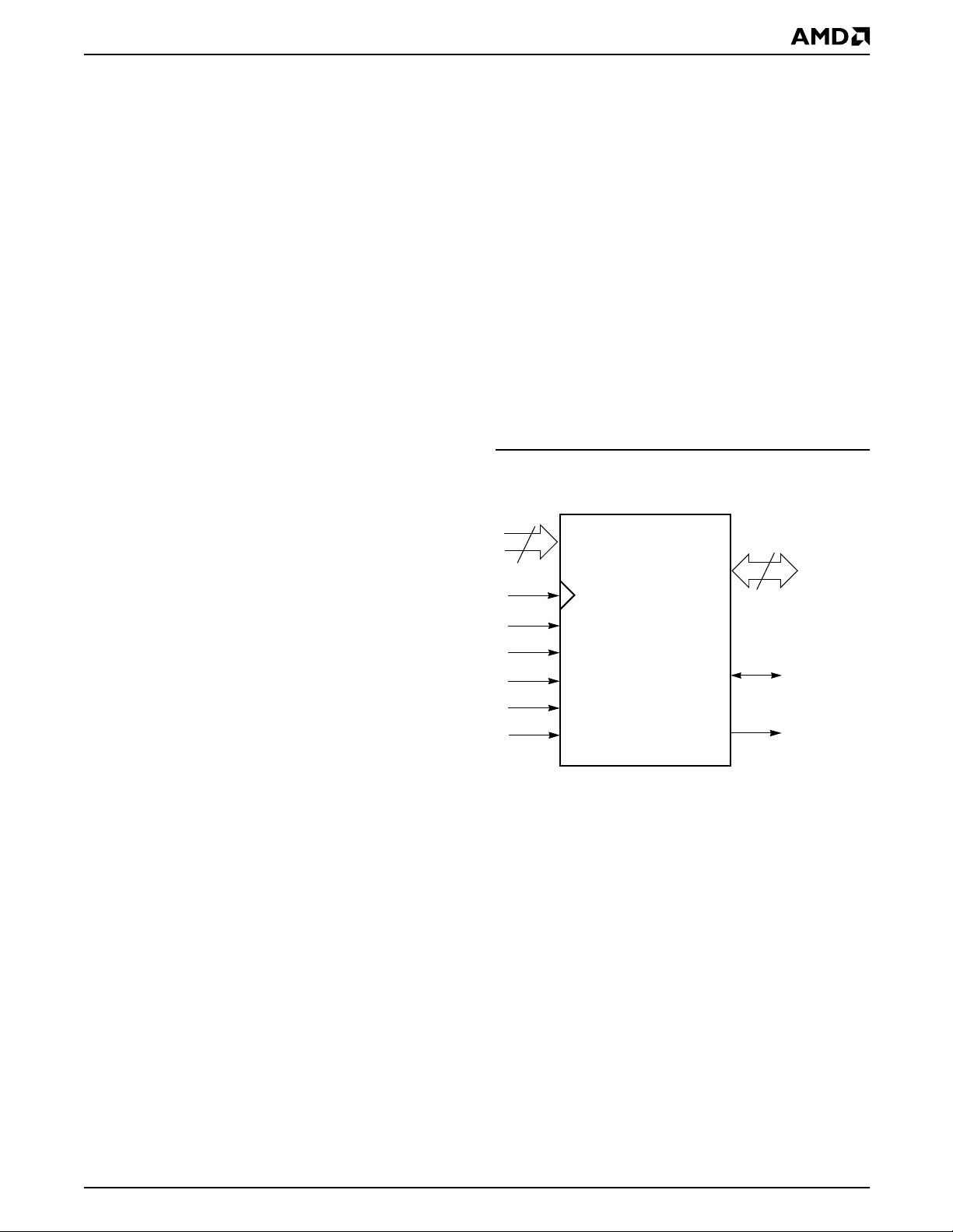
BLOCK DIAGRAM
V
CC
V
SS
RDY
Buffer
WE#
RESET#
V
PP
CE#
OE#
State
Control
Command
Register
Synchronous/Burst Asynchronous
Speed Option
) 120 Max Access Time, ns (t
IACC
) 20 Max CE# Access, ns (tCE)110
BACC
11A
(40 MHz)
Speed Option 11A
ACC
PS
A/DQ0
RDY
Erase Voltage
Generator
PS Buffer
Input/Output
Buffers
PGM Voltage
Generator
Chip Enable
Output Enable
Logic
)110
–A/DQ15
Data
Latch
V
CC
Timer
Detector
AVD#
CLK
Burst
State
Control
Burst
Address
Counter
A0–A20
A/DQ0–A/DQ15
A16–A20
4 Am29BDS323D
Address Latch
Y-Decoder
X-Decoder
Y-Gating
Cell Matrix
PRELIMINARY
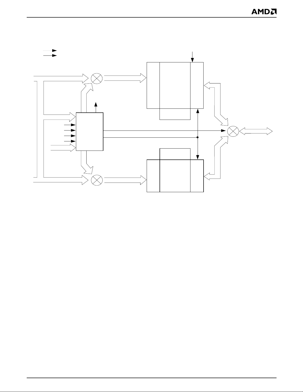
SIMULTANEOUS OPERATION CIRCUIT BLOCK DIAGRAM
V
CC
V
SS
A0–A20
Upper Bank Address
Upper Bank
OE#
Y-Decoder
A0–A20
RESET#
WE#
CE#
ADV#
DQ0–DQ15
16/32#
A0–A20A0–A20
STATE
CONTROL
&
COMMAND
REGISTER
X-Decoder
Status
Control
X-Decoder
Latches and Control Logic
DQ0–DQ15
DQ0–DQ15 DQ0–DQ15
A0–A20
Lower Bank Address
Lower Bank
Y-Decoder
Latches and
Control Logic
Note: A0–A15 are multiplexed wi th DQ0–DQ15.
Am29BDS323D 5
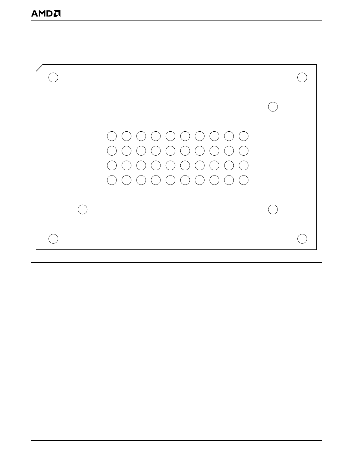
CONNECTION DIAGRAM
PRELIMINARY
47-Ball FBGA
Top View, Balls Facing Down
A1
RDYA2NCA3GNDA4CLKA5V
B1
B2
V
A16B3A20B4AVD#B5PS
CC
C1
C2
A/DQ7C3A/DQ6C4A/DQ13C5A/DQ12C6A/DQ3C7A/DQ2C8A/DQ9C9A/DQ8
GND
D1
A/DQ15D2A/DQ14
D3
D4
GND
A/DQ5D5A/DQ4D6A/DQ11D7A/DQ10
Special Handling Instructions for FBGA Package
Special handling is required for Flash Memory products
in FBGA packages.
CC
A6
WE#A7V
B6
RESET#
A8
A19A9A17
PP
B7
WP#B8A18B9CE#
D8
D9
V
A/DQ1
CC
A10
NC
B10
GND
C10
OE#
D10
A/DQ0
Flash memory devices in FBGA packages may be
damaged if exposed to ultrasonic cleaning methods.
The package and/or data integrity may be
compromised if the package body is exposed to
temperatures above 150°C for prolonged periods of
time.
6 Am29BDS323D
INPUT/OUTPUT DESCRIPTIONS
A16–A20 = Address Inputs
PRELIMINARY
PS = Power Saving input/output
A/DQ0– = Multiplexed Address/Data input/output
A/DQ15
CE# = Chip Enable Input. Asynchronous
relative to CLK for the Burst mode.
OE# = Output Enable Input. Asynchronous
relative to CLK for the Burst mode.
WE# = Write Enable Input.
V
CC
V
SS
= Device Power Supply (1.7 V–1.9 V).
= Ground
NC = No Connect; not connected internally
RDY = Ready output; indicates the status of
the Burst read. Low = data not valid at
expected time. High = data valid.
CLK = The first rising edge of CLK in
conjunction with AVD# low latches
address input and activates burst
mode operation. After the initial word
is output, subsequent rising edges of
CLK increment the internal address
counter. CLK should remain low
during asynchronous access.
AVD# = Address Valid input. Indicates to
device that the valid address is
present on the address inputs
(address bits A0–A15 are multiplexed,
address bits A16–A20 are address
only).
Low = for asynchronous mode,
indicates valid addr es s; for bu rst
mode, causes starting address to be
latched on rising edge of CLK.
High = device ignores address inputs
During a read operation, PS indicates
whether or not the data on the outputs
are inverted. Low = data not inverted;
High = data inverted
RESET# = Hardware reset input. Low = device
resets and returns to rea ding array
data. RESET# must be low during
device power up.
WP# = Hardware write protect input. Low =
disables writes to SA70 and SA71
V
PP
= At 12 V, accelerates programming;
automatically places device in unlock
bypass mode. At V
, disables
IL
program and erase functions. Should
be at V
for all other conditions.
IH
LOGIC SYMBOL
5
A16–A20
CLK
CE#
OE#
WE#
RESET#
AVD#
A/DQ0–
A/DQ15
PS
RDY
16
Am29BDS323D 7
PRELIMINARY
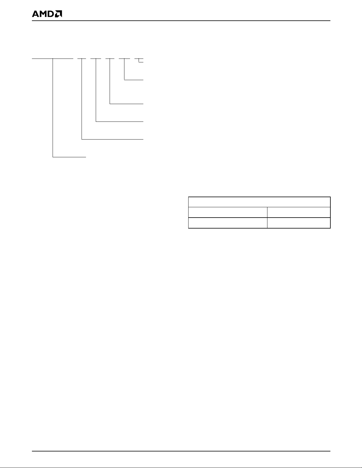
ORDERING INFORMATION
The order number (Valid Combination) is formed by the following:
Am29BDS323D T 11 A WK I
TEMPERATURE RANGE
I = Industrial (–40
PACKAGE TYPE
WK = 47-Ball Fine-Pitch Grid Array (FBGA)
0.50 mm pitch, 7 x 10 mm package (FDD047)
CLOCK RATE
A=40 MHz
SPEED
See Product Selector Gu id e an d Valid Combination
BOOT CODE SECTOR ARCHITECTURE
T = Top sector
DEVICE NUMBER/DESCRIPTION
Am29BDS323D
32 Megabit (2 M x 16-Bit) CMOS Flash Memory, Simultaneous Read/Write, Burst Mode Flash Memory
1.8 Volt-only Read, Program, and Erase
°C to +85°C)
Valid Combinations
Valid Combination configuration planned to be supported for this
device.
Valid Combinations
Order Number Package Marking
Am29BDS323DT11AWKI N323DT1AVI
8 Am29BDS323D
PRELIMINARY
DEVICE BUS OPERATIONS
This section describes the requirements and use of the
device bus operations, wh ich are initiated through the
internal command register. The command register itself
does not occupy any addressable memory location.
The register is composed of latches that store the commands, along with the address a nd data information
needed to execute the command . The conte nts of the
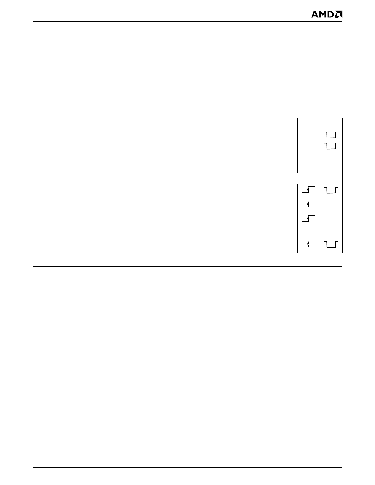
Table 1. Device Bus Operati ons
Operation CE# OE# WE# A16–20 A/DQ0–15 RESET# CLK AVD#
Asynchronous Read L L H Addr In I/O H L
Write L H L Addr In I/O H L
Standby (CE#) H X X HIGH Z HIGH Z H X X
Hardware Reset X X X HIGH Z HIGH Z L X X
Burst Read Operations
Load Starting Burst Address L H H Addr In I/O H
register serve as inputs to the interna l state mach ine.
The state m achine outp uts dictate the functi on of the
device. Table 1 lists the device b us operat ions, the inputs and control level s they require, and the resul ting
output. The following subsections describe ea ch of
these operations in further detail.
Advance Burst to next address with appropriate
Data presented on the Data Bus
Terminate current Burst read cycle H X H HIGH Z HIGH Z H X
Terminate current Burst read cycle via RESET# X X H HIGH Z HIGH Z L X X
Terminate current Burst read cycle and start new
Burst read cycle
Legend: L = Logic 0, H = Logic 1, X = Don’t Care.
Requirements for Asynchronous
Read Operation (Non-Burst)
To read data from the m emor y arra y, the system must
first assert a valid address on A/DQ0–A/DQ15 and
A16–A20, wh ile driving AVD# and CE# to V
should remain at V
for asynchronous read operations. The rising edge of
AVD# latches the address, after which t he sy st em can
drive OE# to V
A/DQ0–A/DQ1 5. Since the m emory arra y is divi ded
into two banks, each bank remains enabled for read
access until the command register contents are
altered.
. Note that CLK must remain low
IH
. The data will appear on
IL
LLHHIGH Z
L H H HIGH Z I/O H
ensures that no sp urious alteration of th e memory
content occurs during the power transition.
Requirements for Synchronous (Burst)
. WE#
IL
Read Operation
The device is capable of continuous, sequential (linear)
burst operation. However, when the device first powers
up, it is enabled for asynchronous read operation. The
device will automatically be enabled for burst mode on
the first rising edge on the CLK input, while AVD# is
held low for one clock cycle. Prior to activating the clock
signal, the system should determine how many wait
states are desired for the ini tial word (t
Burst
Data Out
HH
) of each
IACC
burst session. The system would then write the Set
Address access time (t
stable addresses to valid out put dat a. Th e ch ip ena bl e
access time (t
) is the delay from the stable
CE
addresses and stable CE# to valid data at the outputs.
The output enable access time (t
the falling edge of OE# to valid data at the output.
The internal state machine is set for reading array data
upon device power-up, or af ter a har dware r eset. This
) is equal to the dela y from
ACC
) is the delay from
OE
Wait Count command seq uence (see “Programmable
Wai t St at e ”). The system may optionally activate the
PS mode (see “Power Saving Function”) by writing the
Enable PS Mode comma nd seque nce at thi s time, but
note that the PS mode can only be disabled by a hardware reset. (See “Command Definitions” for further
details).
The initial word is outpu t t
after the rising edge of
IACC
the first CLK cycle. Subsequent words are output t
BACC
Am29BDS323D 9

PRELIMINARY
after the rising edge of each successive clock cycle,
which automatically increments the internal address
counter. Note that the device has a fixed internal
address boundary that occurs every 64 words,
starting at address 00000h. During the time the
device is outputting the 64th word (address 0003Fh,
0007Fh, 000BFh, etc.), a one cycle latency occurs
before data appears for the next address (address
00040h, 00080h, 000C0h, et c.). The RDY ou tput indicates this conditio n to the syste m by pulsin g low. See
Figure 17.
The device will continue to output sequential burst
data, wrapping around to address 00000h after it
reaches the highest addressable memory location,
until the system asserts CE# high, RESET# low, or
A VD# low in conjunction with a new address. See T able
1. The reset co mmand does not t erminate the bu rst
read operation.
If the host system crosses the bank boundary while
reading in burst mo de, an d the devi ce is not prog ramming or erasing, a one cycle latency wi ll occur as
described above. If the host system cr osses the bank
boundary while the d evice i s program ming or er asing,
the device will provide asynchronous read status information. The clock will be ignored. After the host has
completed st atus reads, or the device has completed
the program or era se op eration, the h ost can rest art a
burst operation using a new address and AVD# pulse.
If the clock frequency is less than 6 MHz during a burst
mode operation, additional late ncies will occur. RDY
indicates the length of the latency by pulsing low.
Programmable Wait State
The programmable wait state feature indicates to the
device the number of addi ti onal cloc k c ycle s th at m ust
elapse after AVD# is driven active befor e data will be
available. Upon power up, the device defaults to the
maximum of seven total cyc les. The total number of
wait states is programmable from four to seven cycles.
See Figur e 20.
Power Saving Function
The Power Save function r educes the amount of
switching on th e data output bus by cha nging the
minimum number of bits possible, thereby reducing
power consumption. This fun ction is acti ve on ly durin g
burst mode operations.
The device compares the word previously output to the
system with the new word to be output. If the number of
bits to be switched is 0–8 (less than half the bus width),
the device simply o utputs the new word on the data
bus. If, however, the number of bits that must be
switched is 9 or higher, the data is inverted before being
output on the data bus. This effectively limits the
maximum number of bits that are switched for any
given read cy cle to eight. The device i ndicates to the
system whether or not the data is inverted v ia the PS
(power saving) output. If the word on the data bus is not
inverted, PS = V
inverted, PS = V
; if the word on the data bus is
OL
.
OH
During initial power up the PS function i s disabled. To
enable the PS function, the system must write the
Enable PS command sequence to the flash device (see
the Command Definitions table).
When the PS fu nc tio n is enabled, one ad dit ion al c lo ck
cycle is inserted during the initial and second access of
a burst sequence. See Figure 18. The RDY output indicates this condition to the system.
The device is also capable of receiving inverted data
during program operations. The host system must indicate to the device via the PS in put whether or n ot the
program data are inverted. PS must be driven to V
inverted data, or to V
for non-inverted data.
IL
IH
for
To disable the PS function, the system must hardware
reset the device (drive the RESET# input low).
Simultaneous Read/Write Operations with
Zero Latency
This device is capable of reading data from one bank
of memory while programming or erasing in the other
bank of memory. An erase operation may also be su spended to read from or program to another location
within the same bank (except the sector being
erased). Figu re 21 s hows how read and w rite cycles
may be initiated for simultaneous operation with zero
latency. Refer to the DC Characteristics table for
read-while-program and r ead-while-erase c urrent
specifications.
Writing Commands/Command Sequences
The device has inputs/outputs that accept both address and data information. To write a command or
command sequenc e (which includes programming
data to the device and erasing sectors of memory), the
system must drive CLK, AVD# and CE# to V
OE# to V
and drive CLK, WE# an d CE# to V
when providing an address to the device,
IH
, and OE# to VIH.
IL
when writing commands or data.
The device features an Unlock Bypass mode to facili-
tate faster progr amming. Once a bank enters the
Unlock Bypass mode, only two write cycles are required to program a word, instead of four.
An erase operation can erase one sector, multiple sectors, or the entire device. Table 2 indicates the address
space that each sector occupies. The device address
space is divided into two banks: Bank A contains the
boot/parameter sectors, and B ank B contains the
larger, code sectors of uniform size. A “bank address”
is the address bits required to uniquely select a bank.
Similarly, a “sector address” is the address bits required to uniquely select a sector.
, and
IL
10 Am29BDS323D

PRELIMINARY
I
in the DC Characteristics table represents the ac-
CC2
tive current specification for the write mode. The AC
Characteristics section contains timing specification
tables and timing diagrams for write operations.
addresses are changed. While in sl eep mode, output
data is latc hed and always a vailable to the system .
in the DC Characteristics table represents the
I
CC4
automatic sleep mode current specification.
Accelerated Program Operation
The device offers accelerated p rogram operat ions
through V
. This function is primarily intended to
PP
allow faster manufact uring thr oughp ut at the factory. If
the system asserts V
on this input, the device auto-
ID
matically enters the aforemention ed Unlock B ypass
mode, temporarily unprotects any protected sectors,
and uses the higher voltag e on the input to reduce the
time required for program operations. The system
would use a two-cycle program command sequence
as required by the Unloc k Bypass mo de. Removing
from the VPP input returns the device to normal op-
V
ID
eration. Note th at sect ors mus t be unl ocked usi ng the
Sector Lock/Unlock command sequence prior to raising V
to VID.
PP
Autoselect Functions
If the system writes the autoselect command sequence, the device enters the autoselect mode. The
system can then read autosel ect cod es fro m the internal register (which is separate from the memory array)
on DQ7–DQ0. Stand ard read cy cle timings apply in
this mode. Refer to the Autoselect Functions and Autoselect Command Sequence sections for more
information.
Standby Mode
When the system is not reading or writing to the device, it can place the device in the standby mode. In
this mode, current consumption is greatly reduced,
and the outputs are placed in the high impedance
state, independent of the OE# input.
The device enters th e CMOS s tandby mode when th e
CE# and RESET# inputs are both held at V
The device requires standard access time (t
± 0.2 V.
CC
CE
) for
read access when the device is in either of these
standby modes, before it is ready to read data.
If the device is deselecte d during erasur e or programming, the device draws active current until the
operation is completed.
in the DC Characteristics table represents the
I
CC3
standby current specif ic ati on.
Automatic Sleep Mode
The automatic sleep mode minimizes Flash device energy consumption. The device automati cally enables
this mode when addresses remain stabl e for t
60 ns. The automa tic sleep mode is indepe ndent of
the CE#, WE#, and OE# contro l sign als. St andard ad dress access timi ngs provide new data when
ACC
+
RESET#: Hardware Reset Input
The RESET# input pro vides a h ardwa re met hod of r esetting the device to reading array data. When
RESET# is driven low for at least a period of t
RP
, the
device immediately terminates any operation in
progress, tristates al l outputs, and ignores all
read/write commands for the duration of the RESET#
pulse. The device al so resets the i nternal state machine to reading arra y data. The o peration that was
interrupted should be reinitiated once the device is
ready to accept another command sequence, to ensure data integrity.
Current is reduced for the duration of the RESET#
pulse. When RESET# is held at V
draws CMOS standby current (I
held at V
but not within VSS±0.2 V, the standby cur-
IL
±0.2 V, the device
SS
). If RESET# is
CC4
rent will be greater.
RESET# may be tied to the system reset circuitry. A
system reset would thus a lso res et the Flash m emory,
enabling the system to read the boot-up firmware from
the Flash memory. Note that RESET# must be asserted low during device power-up for proper
operation.
If RESET# is asserted during a program or erase operation, the device requires a time of t
READY
(during
Embedded Algorithms) before the device is ready to
read data again. If RESET# is asserted when a program or erase operation is not executing, the reset
operation is completed within a time of t
READY
(not
during Embedded Algorithms). The system can read
data t
after RESET# returns to VIH.
RH
Refer to the AC Characteristics tables for RESET# parameters and to Figure 11 for the timing diagram.
Output Disable Mode
When the OE# input is at VIH, output from the device
is disabled. The ou tputs are placed in the high
impedance state.
Hardware Data Protection
The command sequence r equ irement of unlock cycles
for programming or erasing provides data protection
against inadvertent writes ( refer to Table 4 for command definitions).
The device offers three types of data protection at the
sector level:
■ The sector lock/unlock command sequence dis-
ables or re-enables both program and erase operations in any sector.
Am29BDS323D 11

PRELIMINARY
■ When WP# is at V
the two outermost sec tors a r e
IL,
locked.
■ When V
is at VIL, all sectors are locked.
PP
The following hardware data pr ot ec tio n measur es prevent accidental erasure or programming, which might
otherwise be cau sed by sp urious sy stem level s ignals
during V
power-up and power-down trans itions, or
CC
from system noise.
Low V
When V
cept any write cycles. This protects data during V
Write Inhibit
CC
is less than V
CC
, the device does not ac-
LKO
CC
power-up and power-down. The command register
and all internal program/erase circuits are disabled,
and the device resets to reading array data. Subse-
quent writes are ignored until V
. The system must provide the proper signals to
V
LKO
is greater than
CC
the control inputs to pr event unintent ional wri tes when
is greater than V
V
CC
LKO
.
Write Pulse “Glitch” Prote ct i o n
Noise pulses of less than 5 ns (typic al) on OE#, CE#
or WE# do not initiate a write cycle.
Logical Inhibit
Write cycles are inhibited by holding any one of OE# =
V
, CE# = VIH or WE# = VIH. To initiate a write cycle,
IL
CE# and WE# must be a logical zero while O E# is a
logical one.
12 Am29BDS323D
Bank B
PRELIMINARY
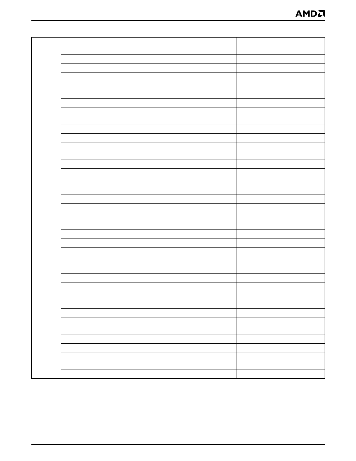
Table 2. Sector Address Table
Sector Sector Size (x16) Address Range
SA0 32 Kwords 00000h—07FFFh
SA1 32 Kwords 08000h—0FFFFh
SA2 32 Kwords 10000h—17FFFh
SA3 32 Kwords 18000h—1FFFFh
SA4 32 Kwords 20000h—27FFFh
SA5 32 Kwords 28000h—2FFFFh
SA6 32 Kwords 30000h—37FFFh
SA7 32 Kwords 38000h—3FFFFh
SA8 32 Kwords 40000h—47FFFh
SA9 32 Kwords 48000h—4FFFFh
SA10 32 Kwords 50000h—57FFFh
SA11 32 Kwords 58000h—5FFFFh
SA12 32 Kwords 60000h—67FFFh
SA13 32 Kwords 68000h—6FFFFh
SA14 32 Kwords 70000h—77FFFh
SA15 32 Kwords 78000h—7FFFFh
SA16 32 Kwords 80000h—87FFFh
SA17 32 Kwords 88000h—8FFFFh
SA18 32 Kwords 90000h—97FFFh
SA19 32 Kwords 98000h—9FFFFh
SA20 32 Kwords A0000h—A7FFFh
SA21 32 Kwords A8000h—AFFFFh
SA22 32 Kwords B0000h—B7FFFh
SA23 32 Kwords B8000h—BFFFFh
SA24 32 Kwords C0000h—C7FFFh
SA25 32 Kwords C8000h—CFFFFh
SA26 32 Kwords D0000h—D7FFFh
SA27 32 Kwords D8000h—DFFFFh
SA28 32 Kwords E0000h—E7FFFh
SA29 32 Kwords E8000h—EFFFFh
SA30 32 Kwords F0000h—F7FFFh
SA31 32 Kwords F8000h—FFFFFh
SA32 32 Kwords 100000h—107FFFh
SA33 32 Kwords 108000h—10FFFFh
SA34 32 Kwords 110000h—117FFFh
SA35 32 Kwords 118000h—11FFFFh
SA36 32 Kwords 120000h—127FFFh
SA37 32 Kwords 128000h—12FFFFh
Am29BDS323D 13
Bank B
Bank A
PRELIMINARY
Table 2. Sector Address Table (Continued)
Sector Sector Size (x16) Address Range
SA38 32 Kwords 130000h—137FFFh
SA39 32 Kwords 138000h—13FFFFh
SA40 32 Kwords 140000h—147FFFh
SA41 32 Kwords 148000h—14FFFFh
SA42 32 Kwords 150000h—157FFFh
SA43 32 Kwords 158000h—15FFFFh
SA44 32 Kwords 160000h—167FFFh
SA45 32 Kwords 168000h—16FFFFh
SA46 32 Kwords 170000h—177FFFh
SA47 32 Kwords 178000h—17FFFFh
SA48 32 Kwords 180000h—187FFFh
SA49 32 Kwords 188000h—18FFFFh
SA50 32 Kwords 190000h—197FFFh
SA51 32 Kwords 198000h—19FFFFh
SA52 32 Kwords 1A0000h—1A7FFFh
SA53 32 Kwords 1A8000h—1AFFFFh
SA54 32 Kwords 1B0000h—1B7FFFh
SA55 32 Kwords 1B8000h—1BFFFFh
SA56 32 Kwords 1C0000h—1C7FFFh
SA57 32 Kwords 1C8000h—1CFFFFh
SA58 32 Kwords 1D0000h—1D7FFFh
SA59 32 Kwords 1D8000h—1DFFFFh
SA60 32 Kwords 1E0000h—1E7FFFh
SA61 32 Kwords 1E8000h—1EFFFFh
SA62 32 Kwords 1F0000h—1F7FFFh
SA64 4 Kwords 1F8000h—1F8FFFh
SA65 4 Kwords 1F9000h—1F9FFFh
SA66 4 Kwords 1FA000h—1FAFFFh
SA67 4 Kwords 1FB000h—1FBFFFh
SA68 4 Kwords 1FC000h—1FCFFFh
SA69 4 Kwords 1FD000h—1FDFFFh
SA70 4 Kwords 1FE000h—1FEFFFh
SA71 4 Kwords 1FF000h—1FFFFFh
14 Am29BDS323D

PRELIMINARY
COMMAND DEFINITIO N S
Writing specific address and data commands or
sequences in to the command regi ster initiates device
operations. Table 4 defines the valid register command
sequences. Writing incorrect address and data
values or writing them in the improper sequence
resets the device to reading array data.
All addresses are latc hed on th e rising e dge of AVD#.
All data is latch ed on th e risin g edge o f WE#. Refer t o
the AC Characteristics section for timing diagrams.
Reading Array Data
The device is automatically set to reading array data
after device p ower-up. No co mmands are re quired to
retrieve data in asynchronous mode. Each bank is
ready to read array data after completing an
Embedded Program or Embedded Erase algorithm.
After the device accepts an Erase Suspend command,
the corresponding bank enters the erase-suspend-read mode, after which the system can read data
from any non-erase-suspended sector within the same
bank. After completing a programming operation in the
Erase Suspend mode, the system may once again
read array data with the same ex ception. See the
Erase Suspend/Erase Resume Commands section for
more information.
The system must issu e the re set c omm and to r eturn a
bank to the read (or erase-suspend-read) mode if DQ5
goes high during an active program or erase operation,
or if the bank is in the autoselect mode. See th e next
section, Reset Command, for more information.
See also Requirements for Asynchronous
Read Operation (Non-Burst) and Requirements for
Synchronous (Burst) Rea d Operation in the Device
Bus Operations section for more information. Th e
Asynchronous Read and Synchronous/Burst Read
tables provide the read parameters, and Figures 9 and
10 show the timings.
Set Wait State Command Sequence
The wait state command sequence instructs the device
to set a particu lar nu mber of cloc k cyc les for the init ial
access in burst m ode. The number of w ait states tha t
should be programmed into the device is directly
related to the clock frequency. The first two cycles of
the command sequence are for unlock purposes. On
the third cycle, the system should write C0h to the
address associated with the intended wait state setting
(see T able 3). Address bits A12 and A13 determine the
setting.
T a ble 3. Third Cycle Address/Data
Address Total Wait State Cycles Data
000555h 4
001555h 5
002555h 6
003555h 7
Upon power up, the device defaults to the maximum
seven cycle wait state setting (see Figure 20). It is recommended that the wait s tate c omman d se quence be
written, even if the defau lt wait stat e value is desir ed, to
ensure the device is set as expected. A hardware reset
will set the wait state to the default setting.
C0h
Enable PS (Power Saving) Mode
Command Sequence
The Enable PS (Power Saving) Mode command
sequence is required to set the device to the PS mode.
On power up, th e Pow er Sa ving mo de is disa bled . The
command sequenc e consists of two unloc k cycles followed by a command cycle in which the addr ess and
data should 555h/70h, respectively. The PS mode
remains enabled u ntil the device is ha rdware reset
(either device is powered down or RESET# is asserted
low).
Sector Lock/Unlock Command Sequence
The sector lock/unlock c omm and seq uen ce allows the
system to determi ne wh ich se cto rs are protec ted f rom
accidental writes. When the device is first powered up,
all sectors are loc ked. To unlock a sector, the system
must write the sector lock/unlock command sequence.
Two cycles are first writ ten: addres ses are don’t c are
and data is 60h. During the third cycle, the sector
address (SLA) and unlock command (60h) is written,
while specifying with address A6 whether that sector
should be lock ed (A6 = V
After the th ird cy cle, the s yste m can conti nue to lo ck or
unlock additional cycles, or exit the sequence by
writing F0h (reset command).
Note that the last two outermost boot sectors can be
locked by taking th e WP# signa l to V
all sectors are lo cked; if t he VPP input is at VPP,
at V
IL
all sectors are unlocked.
) or unlocked (A6 = VIH).
IL
. Also, if VPP is
IL
Reset Command
Writing the reset command resets the banks to the read
or erase-suspend-read mode. Address bits are don’t
cares for this command.
The reset command m ay be written between the
sequence cycles in an erase command sequence
before erasing begins. This resets the bank to which
Am29BDS323D 15

PRELIMINARY
the system was writing to the read mode. Once erasure
begins, however, the device ignore s reset commands
until the operation is complete.
The reset comman d may be written between the
sequence cycles in a program com mand sequence
before programmin g begins. This resets the bank to
which the system was writi ng to the read mo de. If the
program command seque nce is written to a bank that
is in the Erase Suspend mode, writing the reset
command returns that bank to the erase-suspend-read
mode. Once programming begins, however, the device
ignores reset commands until the operation is complete.
The reset comman d may be written between the
sequence cycles in an autoselect command sequence.
Once in the autoselect mode, the reset command must
be written to return to the read mode. If a bank entered
the autoselect mode while in the Erase Suspend mode,
writing the reset command return s that bank to the
erase-suspend-read mode.
If DQ5 goes high during a program or erase operation,
writing the reset command returns the banks to the
read mode (or eras e-suspend-read m ode if that bank
was in Erase Suspend).
Program Command Sequence
Programming is a four-bus-cycle operation. The
program command sequence is initiated by writing two
unlock write cycles, followed by the program set-up
command. The program addr ess and data are written
next, which in turn initiate the Embedded Program
algorithm. The system is not required to provide further
controls or timings. The de vice automati cally pro vides
internally generated progra m pulses and verifies the
programmed cell margin. Table 4 shows the address
and data requirements for the program command
sequence.
When the Embed ded Program algo rithm is compl ete,
that bank then returns to the read mode and addresses
are no longer latc hed. The system can d etermine the
status of the program operati on by moni toring DQ7 or
DQ6/DQ2. Refer to the Write Operation Status section
for information on these status bits.
Any commands written to the device during the
Embedded Program Algorithm are ignored. Note that a
hardware reset immediately terminates the program
operation. The program command sequence should be
reinitiated once that bank has returned to the read
mode, to ensure data integrity.
Autoselect Command Sequence
The autoselect command sequence allows the host
system to access the man ufacturer and dev ice cod es,
and determine whether or not a sector is protected.
T able 4 shows the address and data requirements. The
autoselect command sequence may be written to an
address within a bank that is either in the r ead or
erase-suspend-read mode. The autoselect command
may not be written while the device is actively programming or erasing in the other bank.
The autoselect command sequence is ini tiated by firs t
writing two unlock cycles . This is followed by a third
write cycle that contains the bank address and the
autoselect co mmand. The bank then enter s the
autoselect mode. The system may read at any address
within the same bank any numbe r of ti mes withou t initiating another autoselect command sequence:
■ A read cycle at ad dress (BA)XX00h (wher e BA is
the bank address) returns the manufacturer code.
■ A read cycle at address (BA)XX01h returns the
device code.
■ A read cycle to an ad dress containi ng a secto r address (SA) within the same bank , and the address
0002h on A15–A0 returns 0001h if th e sector is
locked, or 0000h if it is unlock ed. (Refe r to Table 2
for valid sector addresses).
The system must write the reset command to return to
the read mode (or erase-suspend-read mode if the
bank was previously in Erase Suspend).
Programming is allowed in a ny sequenc e and across
sector boundaries. A bit cannot be programmed
from “0” back to a “1.” Attempting to do so may
cause that bank to set DQ5 = 1, or cause the DQ7 and
DQ6 status bit to indicate the operation was successful. However, a succeeding read will show that the
data is still “0.” Only erase operations can convert a “0”
to a “1.”
Unlock Bypass Command Sequence
The unlock bypass feature allows the system to
program to a bank faster than using the standard
program command sequence. The unlock bypass
command sequence is initiated by first writing two
unlock cycles . This is followed by a third write cycl e
containing the unlock bypass command, 20h. That
bank then enters the unlock bypass mode. A two-cycle
unlock bypass progr am com mand se quenc e is al l that
is required to p rogram in this mode . The first cycl e in
this sequence contain s the unlock bypass program
command, A0h; the second cycle contains the program
address and data. Add itional data is progra mmed in
the same manner. This mode dispenses with the initial
two unlock cycles required in the standard program
command sequence, resulting i n faster to tal programming time. The host s ystem may also i nitiate the chi p
erase and sec tor erase sequences i n the unlock
bypass mode. The erase command sequen ces are
four cycles in length instead of six cycles. Table 4
shows the requirements for the command sequence.
16 Am29BDS323D

PRELIMINARY
During the unlock bypass mode, only the Unlock
Bypass Program and Unlock Bypass Reset commands
are valid. To exit the unlock bypass mode, the s ystem
must issue the two-cycle unlock bypass reset
command sequence. The first cycle must contain the
bank address and the data 90h. The second cycle
need only contain the data 00h. The bank then returns
to the read mode.
The device offers accelerated program operations
through V
. When the system asserts VID on this
PP
input, the device automatically enters the Unlock
Bypass mode. The system may then write the
two-cycle Unlock Bypass program command
sequence. The device uses the higher voltag e on the
input to accelerate the operation. Note that sectors
V
PP
must be unlocked using the Sector Lock/Unlock
command sequence prior to raising V
to VID.
PP
Figure 1 illustrates the algorit hm for the progr a m oper ation. Refer to the Erase/Program Operations table in
the AC Characteristics section for parameters, and
Figure 12 for timing diagrams.
START
Write Program
Command Sequence
Chip Erase Command Sequence
Chip erase is a six bus cycle operation. The chip erase
command sequence is initiated by writing two unlock
cycles, followed by a se t-up comm and. Two additional
unlock write cycles are then followed by the chip erase
command, which in tur n in vokes the Embedded E r ase
algorithm. Th e device does not require the system to
preprogram prior to erase. The Embedded Erase algorithm automatically preprograms and verifies the entire
memory for an all zero data pattern prior to electrical
erase. The system is not r equire d to pro vide any controls or timings during these operations.
The host system may also initiate the chip erase
command sequence while the device is in the unlock
bypass mode. The command sequence is two cycles
cycles in length instead of six cycles. T able 4 shows the
address and data requiremen ts for the chip erase
command sequence.
When the Embedded Erase algorithm is complete,
that bank returns t o the read m ode and addresses are
no longer latched. The system can determine the status of the erase operation by usin g DQ7 or DQ6/DQ2 .
Refer to the Write Operatio n Status sect ion for infor mation on these status bits.
Any commands written during the chip erase operation
are ignored. However, note that a hardware reset
immediately terminates the era se operation. If t hat
occurs, the chip era se command s equence should b e
reinitiated once that bank has returned to reading array
data, to ensure data integrity.
Data Poll
Embedded
Program
algorithm
in progress
Increment Address
Note: See Table 4 for program command sequence.
No
from System
Verify Data?
Yes
Last Address?
Yes
Programming
Completed
Figure 1. Program Operation
No
Figure 2 illustrates the algorithm for the erase operation. Refer to the Erase/Program Operations table in
the AC Characteristics se ction for parameters, and
Figure 13 section for timing diagrams.
Sector Erase Command Sequence
Sector erase is a six bus cycle operation. The sector
erase command s equence is initi ated by writing two
unlock cycles, followed by a set -up command. Two
additional un lock cycles are writte n, and are then followed by the address o f the sector to be erased, an d
the sector erase command. Table 4 shows the address
and data requirem ents for the se ctor erase com mand
sequence.
The device does not require the system to preprogram
prior to erase. The Embedded Erase algorithm automatically programs an d verifies the en tire memory for
an all zero data pattern prior to electrical erase. The
system is not required to provide any controls or
timings during these operations.
After the command sequence is written, a sector erase
time-out of no less than 50 µs occurs. During the
time-out period, additional sector addresses and sector
erase commands may be written. Loading the sector
Am29BDS323D 17

PRELIMINARY
erase buffer may be done in any seque nce, and the
number of sectors may be from one sector to all sectors. The time between these additional cycles must be
less than 50 µs, otherwise erasure may begin. Any
sector erase address and command following the
exceeded time -out may or may not be accep ted. It is
recommended that processor interrupts be disabled
during this time to ensure all commands are accepted.
The interrupts can be re- enabled after the last Sec tor
Erase command is written. Any command other than
Sector Erase or Erase Suspen d during the time-out
period resets that bank to the read mode. The
system must rewrite the command seque nce and any
additional addresses and commands.
The system can monitor DQ3 to determine if the sector erase timer has timed out (See the section on DQ3:
Sector Er as e Timer.). Th e t im e- ou t be gi n s f ro m t he r i sing edge of the final WE# pulse in the command
sequence.
When the Embedded Erase alg or ith m is compl ete, the
bank returns to read ing array d ata and address es are
no longer latched. Note that while the Embedded Erase
operation is in progress, the system can read data from
the non-erasing bank.
The system c an determ ine the status of t he eras e operation by reading DQ7 or DQ6/ DQ2 in the erasing bank.
Note that the host system must wait 200 µs after the
last sector erase command to obtain status information
if the first status read is in a different bank than the last
sector selected for erasure. For example, if sector 0,
which is in bank B, was the last sector selected for erasure, and the host system requests its first status read
from sector 71, which is in bank A, then the device
requires 200 µs befor e status information will be av ai lable. Refer to the Write Operation Status section for
information on these status bits .
Once the sector erase operation has begun, only the
Erase Suspend command is valid. All other commands
are ignored . However, note that a hardware reset
immediately terminates the erase operation. If that
occurs, the sector erase command sequence should
be reinitiated once that bank has returned to reading
array data, to ensure data integrity.
The host system may also initiate the sector erase
command se quence while the device i s in the unl ock
bypass mode. The com mand sequence is four cycles
cycles in length instead of six cycles.
Figure 2 illu strates the alg orithm for th e erase opera tion. Refer to the Erase/Program Operations table in
the AC Characteristics se ction for parameters, and
Figure 13 section for timing diagrams.
Erase Suspend/Erase Resume Commands
The Erase Suspend command, B0h, allows the system to interrupt a sector erase operation and then read
data from, or pro gr am dat a t o, a ny s ec tor n ot selected
for erasur e. Th e ba nk ad dre ss is requ ired wh en wr iti ng
this command. This command is valid only during the
sector erase operation , including the min imum 50 µs
time-out period during the sector erase command sequence. The Erase S uspend comma nd is ignored i f
written during the chip erase operation or Embedded
Program algorithm.
When the Erase Suspend command is written during
the sector erase operation, the device requires a
maximum of 20 µs to suspend the erase operation.
However, when the Erase Suspend command is
written during the sector erase time-out, the device
immediately terminat es the time-out period and su spends the erase operation.
After the erase operation has been suspended, the
bank enters the eras e-suspend -read mode. Th e
system can read data from or program data to any
sector not selected for erasure. (The device “erase
suspends” all sectors selected for erasure.) Reading at
any address within erase-suspended sectors produces
status information on DQ7 –DQ0. The sys tem can us e
DQ7, or DQ6 and DQ2 together, to determine if a
sector is ac tive l y er as in g or i s er as e-suspended. Ref e r
to the Write Operation Status section for information on
these status bits.
After an erase-suspended program operation is complete, the bank returns to the erase-suspend-read
mode. The system can determine the status of the
program operatio n using the DQ7 or DQ6 s tatus bits,
just as in the standard program operation. Refer to the
Write Operation Status section for more information.
In the erase-suspend-rea d mode, the sys tem can also
issue the autoselec t c om man d s equ ence. Refer to the
Autoselect Functions and Au toselect Command
Sequence sections for details.
T o resume the sector erase operation, the system must
write the Erase Res um e command. The bank add re ss
of the erase-suspe nded bank is requir ed when wr iting
this command. Further writes of the Resume command
are ignored. Another Erase Suspend command can be
written after the chip has resumed erasing.
18 Am29BDS323D

START
Write Erase
Command Sequence
Data Poll
from System
No
Data = FFh?
PRELIMINARY
Embedded
Erase
algorithm
in progress
Yes
Erasure Completed
Notes:
1. See Table 4 for erase command sequence.
2. See the section on DQ3 for information on the sector
erase timer.
Figure 2. E ra se Oper atio n
Am29BDS323D 19

PRELIMINARY
Command Definitions
Table 4. Command Definitions
Bus Cycles (Notes 2–5)
Command Sequence
(Note 1)
Asynchronous Read (Note 6) 1 RA RD
Reset (Not e 7) 1 XXX F0
Manufacturer ID 4 555 AA 2AA 55 (BA)555 90 (BA)X00 0001
Device ID (Note 9) 4 555 AA 2AA 55 (BA)555 90 (BA)X01 22D1 (BA)X03 20/00
(Note 8)
Sector Lock Verify (Note 10) 4 555 AA 2AA 55 (SA)555 90 (SA)X02 00/01
Autoselect
Program 4 555 AA 2AA 55 555 A0 PA Data
Unlock Bypass 3 555 AA 2AA 55 555 20
Unlock Bypass Program (Note 11) 2 XXX A0 PA PD
Unlock Byp a ss Se c to r E r as e ( N ote 11) 2 XX X 80 SA 30
Unlock Byp a s s C hi p Erase (Note 11) 2 XXX 80 XXX 10
Unlock Bypass Reset (Note 12) 2 BA 90 XXX 00
Chip Erase 6 555 AA 2AA 55 555 80 555 AA 2AA 55 555 10
Sector Erase 6 555 AA 2AA 55 555 80 555 AA 2AA 55 SA 30
Erase Suspend (Note 13) 1 BA B0
Erase Res um e (Note 14) 1 BA 30
Sector Lock/Unlock 3 XXX 60 XXX 60 SLA 60
Set Wait Count (Note 15) 3 555 AA 2AA 55 (WS)555 C0
Enable PS Mode 3 555 AA 2AA 55 555 70
First Second Third Fourth Fifth Sixth
Cycles
Addr Data Addr Data Addr Data Addr Data Addr Data Addr Data
Legend:
X = Don’t care
RA = Address of th e me mo ry location to be read.
RD = Data read from location RA during read operation.
PA = Address of the memory location to be programmed. Addresses
latch on the falling e dge of th e WE# or CE# pu lse , which ev er ha pp ens
later.
PD = Data to be programmed at location P A. Data latches on the rising
edge of WE# or CE# pulse, whichever happens first.
Notes:
1. See Table 1 for description of bus operat ions.
2. All values are in hexadecimal.
3. Except for the read cycle and the fourth cycle of the autoselect
command sequence, all bus cycles are write cycles.
4. Data bits DQ15–DQ8 are don’t care in command sequences,
except for RD and PD.
5. Unless otherwise noted, address bits A20–A11 are don’t cares.
6. No unlock or command cycles required when bank is reading
array data.
7. The Reset command is required to return to reading array data
(or to the erase-suspend-read mode if previously in Erase
Suspend) when a bank is in the autoselect mode, or if DQ5 goes
high (while the bank is providing status information).
8. The fourth cycle of the autoselect command sequence is a read
cycle. The system must provide the bank address. See the
Autoselect Command Sequence section for more information.
9. The fifth cycle of the device ID autoselect command sequence is
an extended device ID code. The data is 00h for devices that do
not require additional latency when burst address begins at an
address boundary, and 20h for devices that require additional
latency when burst address begins at an address boundary.
SA = Address of the sect or to be veri fi ed (in au t ose lec t mo de ) or
erased. Address bits A20–A12 uniquely select any sector.
BA = Address of the bank (A20, A19) that is being switched to
autoselect mode, is in bypass mode, or is being erased.
SLA = Address of the sector to be locked. Set sector address (SA) and
either A6 = 1 for unlocked or A6 = 0 for locked.
WS = Number of wait states defined by A12, A13.
10. The data is 0000h for an unlocked sector and 0001h for a locked
sector. All sectors are again locked upon hardware reset.
11. The Unlock Bypass command is required prior to this command
sequence.
12. The Unlock Bypass Reset command is required to return to
reading array data when the bank is in the unlock bypass mode.
13. The system may read and program in non-erasing sectors, or
enter the autoselect mode, when in the Erase Suspend mode.
The Erase Suspend command is valid only during a sector erase
operation, and requires the bank address.
14. The Erase Resume command is valid only during the Erase
Suspend mode, and requires the bank address.
15. The addresses in the third cycle must contain, on A12 and A13,
the additional wait counts to be set. See “Set Wait State
Command Sequence”.
20 Am29BDS323D

PRELIMINARY
WRITE OPERATION STATUS
The device provides several bits to determine the status of
a program or erase operation: DQ2, DQ3, DQ5, DQ6, and
DQ7. Table 6 and the following subsections describe the
function of these bits. DQ7 and DQ6 each offer a method
for determining whether a program or erase operation is
complete or in progress.
when the system samples the DQ7 output, it may read
the status or valid data. Even if the device has completed the program or erase operation and DQ7 has
valid data, the dat a outpu ts on DQ0 –DQ6 may be still
invalid. Valid data on DQ0–DQ7 will appear on successive read cycles.
DQ7: Data# Polling
The Data# Polling bit, DQ7, indicates to the host
system whether an Embedded Program or Erase algorithm is in prog r ess or comp le t e d, or whether a bank is
in Erase Suspend. Data# Polling is valid after the rising
edge of the final WE# pulse in the command sequence.
During the Embedded Program algorithm, the device
outputs on DQ7 the complement of the d atum programmed to DQ7. This DQ7 status also applies to programming during Erase Suspend. When the
Embedded Program al gorithm i s complete, t he devic e
outputs the datum programmed to DQ7. The system
must provide the progr am add re ss to read v al id sta tus
information on DQ7. If a program address falls within a
protected sector, Data# Polling on DQ7 is active for
approximately 1 µ s, th en that bank return s to the r ead
mode.
During the Embedd ed Erase algorith m, Data# Polling
produces a “0” on DQ7. When the Embedded Eras e
algorithm is complete , or if the bank enters the Er ase
Suspend mode, Data# Polling produces a “1” on DQ7.
The system must prov ide an a ddr es s w ith in a ny of th e
sectors selected for erasure to read valid status information on DQ7. Note that the host system must wait
200 µs after the last sec tor erase command to obt ain
status information if the first status read is in a different
bank than the last sector selected for erasure. For
example, if se ctor 0, which is in bank B, was the last
sector selected for eras ure, and the host system
requests its first status read from sector 71, which is in
bank A, then the devi ce requi res 200 µs b efore sta tus
information will be available.
Table 6 shows the outputs for Data# Polling on DQ7.
Figure 3 shows the Data# Po lling algorithm . Figure 15
in the AC Characteristics section shows the Data#
Polling timing diagram.
START
Read DQ7–DQ0
Addr = VA
Yes
Yes
No
DQ7 = Data?
No
DQ5 = 1?
Yes
Read DQ7–DQ0
Addr = VA
DQ7 = Data?
After an erase command sequence is written, if all
sectors sel ected for erasing are pr otected, Data#
Polling on DQ7 is active for approximately 100 µs, then
the bank returns to the read mode. If not all sele cted
sectors are protect ed, the Embedded E rase algorithm
erases the unprotected sectors, and ignores the
selected sectors that are protected. However, if the
system reads DQ7 at an address within a protecte d
sector, the status may not be valid.
Just prior to the compl etion of an Embedded Program
or Erase operation, DQ 7 may change a synchrono usly
with DQ0–DQ6 while Output Enable (OE#) is asserted
low. That is, the device may change from providing
status information to valid data on DQ7. Depending on
Am29BDS323D 21
No
FAIL
Notes:
1. VA = Valid address for programming. During a sector
erase operation, a valid address is any sector address
within the sector being erased. During chip era se, a valid
address is any non-protected sector address.
2. DQ7 should be rechecked even if DQ5 = “1” because
DQ7 may change simultaneously with DQ5.
PASS
Figure 3. Data# Polling Algorithm

PRELIMINARY
RDY: Ready
The RDY is a dedicated outp ut th at in di ca tes (wh en a t
logic low) the system sh ould wait 1 clock cycle before
expecting the next word of data.
RDY functions only whil e reading data in bu rst mode.
Three conditions may cause the RDY output to be low:
during the initi al access (in burst mo de) when PS is
enabled; after the boundary that occurs every 64 words
beginning at address 0000 0h; and when the cloc k frequency is less than 6 MHz ( in which cas e RDY is low
every third clock).
DQ6: T oggle Bit I
Toggle Bit I on DQ6 indicates whether an Embedded
Program or Erase algorithm is in progress or complete,
or whether the device has en tered the Erase Suspend
mode. Toggl e Bit I may be read at any addre ss in the
same bank, and is valid after the rising edge of the final
WE# pulse in the command sequence (prior to the
program or erase operation), and during the sec tor
erase time-out.
During an Embedded Program or Erase algorithm
operation, successive read cycles to any address
cause DQ6 t o toggle. No te that OE# m ust be low duri ng
toggle bit status reads. When the operation is complete, DQ6 stops toggling.
After an erase command sequence is written, if all
sectors selected for erasing are protected, DQ6
toggles for approximately 100 µs, then returns to
reading array data . If not all selected sectors a re protected, the Embedded Erase algorithm erases the
unprotected sectors, and ignores the sel ected sectors
that are protected.
command sequence is w ritten, the n returns to rea ding
array data.
DQ6 also toggles during the erase-suspend-program
mode, and stops toggling once the Embedded
Program algorithm is complete.
See the following for additional information: Figure 4
(toggle bit flowchart), DQ6: Toggle Bit I (description),
Figure 16 (toggle bit timing diagram), and Table 5
(compares DQ2 and DQ6).
START
Read Byte
(DQ0-DQ7)
Address = VA
Read Byte
(DQ0-DQ7)
Address = VA
No
No
DQ6 = Toggle?
Yes
DQ5 = 1?
Yes
Note that the host system must wait 200 µs after the
last sector erase command to obtain status information
if the first status read is in a different bank than the last
sector selected for erasure. For example, if sector 0,
which is in bank B, was the last sector selected for erasure, and the host system requests its first status read
from sector 71, which is in bank A, then the device
requires 200 µs befor e status information will be av ai lable.
The system can use DQ6 and DQ2 together to determine whether a sector is actively erasing or is
erase-suspended. Wh en the device is activel y erasin g
(that is, the Embedded Erase algorithm is in progress),
DQ6 toggles . When the device enters th e Erase
Suspend mode, DQ6 stops toggling. However, the
system must also use DQ2 to determine which sectors
are erasing or erase-suspended. Alternatively, the
system can use DQ7 (see the subse ction on DQ7:
Data# Polling).
If a program address falls within a protected sector,
DQ6 toggles for approx imately 1 µs afte r the program
Read Byte Twice
(DQ 0-DQ7)
Adrdess = VA
DQ6 = Toggle?
Yes
FAIL PASS
Note: The system sh ould recheck the to ggle bit even if DQ5
= “1” because the toggle bit may stop toggling as DQ5
changes to “1.” See the subsections on DQ6 and DQ2 for
more information.
No
Figure 4. Toggle Bit Algorithm
22 Am29BDS323D

PRELIMINARY
DQ2: Toggle Bit II
The “Toggle Bit II” on DQ2, whe n u sed wi th DQ6, indi-
cates whether a particular sector is actively erasing
(that is, the Embedded Erase algorithm is in progress),
or whether that sector is eras e-suspended. Toggle Bit
II is valid after the rising edge of the final WE# pulse in
the command sequence.
DQ2 toggles when the system reads at addresses
within those sectors that have been selected for erasure. Note that OE# must be low during toggle bit
status reads. But DQ2 canno t distinguish whether th e
sector is actively era sing or is erase -su spe nded. DQ6,
by comparison, indicates whether the device is actively
erasing, or is in Erase Suspend, but cannot distinguish
which sectors are selected for erasure. Thus, both
status bits are required for sector and mode information. Refer to Ta ble 6 to comp are ou tputs for DQ2 an d
DQ6.
See the following for additional information: Figure 4
(toggle bit flowchart), DQ6: Toggle Bit I (description),
Figure 16 (toggle bit timing diagram), and Table 5
(compares DQ2 and DQ6).
Table 5. DQ6 and DQ2 Indications
If device is and the system reads then DQ6 and DQ2
programming, at any address, toggles, does not toggle.
at an address within a sector
selected for erasure,
actively erasing,
at an address within sectors not
selected for erasure,
at an address within a sector
selected for erasure,
erase suspended,
at an address within sectors not
selected for erasure,
toggles, also toggles.
toggles, does not toggle.
does not toggle, toggles.
returns array data,
returns array data. The system can read
from any sector not selected for erasure.
programming in
erase suspend
at any address, toggles, is not applicable.
Reading Toggle Bits DQ6/DQ2
Refer to Figu re 4 for the following d iscussion. Whenever the system initially begins reading toggle bit
status, it must read DQ7–DQ0 at least twice in a row to
determine whether a toggle bit is toggling. Typically, the
system would note and store the value of the toggle bit
after the first read. Aft er the second read, the s ystem
would compare the new value of the toggle bit with the
first. If the toggle bit is not toggling, the device has completed the program or erase operation. The system can
read array data on DQ7–DQ0 on the following read
cycle.
However, if after the initial two read cycles, the system
determines that the toggle bit is still toggling, the
system also sh ould note whether the value of DQ5 is
high (see the section on DQ5). If it is, the system
should then determine aga in whether the toggle bit is
toggling, since the toggle bi t may have stopped toggling just as DQ5 went high. If the toggle bit is no longer
toggling, the device has successfully completed the
program or erase operation. If it is still toggling, the
device did not completed the operation succes sfully,
and the system must write the reset command to return
to reading array data.
The remaining scenario is that the system i nitially
determines that the toggle bit is toggl ing and DQ 5 has
not gone high. The system may continue to monitor the
toggle bit and DQ5 through successive read cycles,
determining the status as described in the previous
paragraph. Alternatively, it may choose to perform
other system tasks. In this case, the system must start
at the beginning of the algorithm when it returns to
determine the status of the operation (top of Figure 4).
DQ5: Exceeded Timing Limits
DQ5 indicates whether the program or erase time has
exceeded a specified internal pul se count limit. Un der
these conditions DQ5 produces a “1,” indicating that
the program or erase c ycle was not successfully
completed.
The device may output a “1” on DQ5 if the system tries
to program a “1” to a locatio n that was pre viously programmed to “0.” Only an erase operation can
change a “0” back to a “1.” Under this condition, the
Am29BDS323D 23

PRELIMINARY
device halts the operation, and when the timing limit
has been exceeded, DQ5 produces a “1.”
Under both these conditions, the system must wr ite
the reset command to return to the read mode (or to
the erase-suspend-read mode if a bank was previously in the erase-suspend-program mode).
See also the S ector Erase Com mand Sequence section.
After the sector erase comman d is writte n, the syste m
should read the status of DQ7 (Data # Pollin g) or DQ6
(Toggle Bit I) to ensure that the device has accepted
the command sequence, and then read DQ3. If DQ3 is
“1,” the Embedded Erase algorithm has begun; all
DQ3: Sector Erase Timer
After writing a sector erase command sequence, the
system may read DQ3 to determine whether or not
erasure has begu n. (The sector erase timer does not
apply to the chip erase command.) If additional sectors
are selected for erasure, the entire time-out also
applies after each additional sector erase command.
When the time-out period is complete, DQ3 switches
from a “0” to a “1.” If the time between additional sector
erase commands from the sy stem can b e ass umed t o
further commands (except Erase Suspend) are ignored
until the erase operation is complete. If DQ3 is “0,” the
device will accep t additional sector erase commands.
To ensu re the command has been accepted , the
system software shou ld check the status of DQ3 p rior
to and following each subsequent sector erase command. If DQ3 is high on the second statu s check, the
last command might not have been accepted.
Table 6 shows the status of DQ3 relative to the other
status bits.
be less than 50 µs, the system ne ed n ot monitor DQ3.
Table 6. Write Op eration St atus
DQ7
Status
Standard
Mode
Erase
Suspend
Mode
Notes:
1. DQ5 switches to ‘1’ when an Embedded Program or Embedded Erase operation has exceeded the maximum timing limits.
Refer to the section on DQ5 for more information.
2. DQ7 and DQ2 require a valid address when reading s tatus informat ion. Refer to the appropriate s ubsection for furth er details.
3. When reading write operati on status bi ts, the system must always provide the bank address w here the Embedde d Algorith m
is in progress. The device outputs array data if the system addresses a non-busy bank.
4. The system may read e ither asy nchronous ly or sync hronousl y (burst) w hile in erase suspe nd. RDY w ill funct ion exac tly as in
non-erase-suspended mode.
Embedded Program Algorithm DQ7# Toggle 0 N/A No toggle
Embedded Erase Algorithm 0 Toggle 0 1 Toggle
Erase
Erase-Suspend-
Read (Note 4)
Erase-Suspend-Program DQ7# Toggle 0 N/A N/A
Suspended Sector
Non-Erase Suspended
Sector
(Note 2) DQ6
1 No toggle 0 N/A Toggle
Data Data Data Data Data
DQ5
(Note 1) DQ3
DQ2
(Note 2)
24 Am29BDS323D

PRELIMINARY
ABSOLUTE MAXIMUM RATINGS
Storage Temperature
Plastic Packages . . . . . . . . . . . . . . . –65°C to +150°C
Ambient Temperature
with Power Applied . . . . . . . . . . . . . –65°C to +125°C
Voltage with Respect to Ground,
All I/Os except V
(Note 1). . . . . . . . . . . . . . . . . .–0.5 V to +2.5 V
V
CC
V
(Note 2) . . . . . . . . . . . . . . . . .–0.5 V to +12.5 V
PP
Output Short Circuit Current (Note 3) . . . . . . 100 mA
Notes:
1. Minimum DC voltage on input or I/Os is –0.5 V. During
voltage transitions, input at I/Os may undershoot V
–2.0 V for periods of up to 20 ns du ring voltage trans itions
inputs might overshooot to V
20 ns. See Figure 5. Maximu m DC vol tage on ou tput and
I/Os is V
may overshoot to V
Figure 6.
2. Minimum DC input voltage on V
voltage transitio ns , V
periods of up to 20 ns . Se e Fi gure 5. Maximum DC input
voltage on V
V for periods up to 20 ns.
3. No more than one output may be shorted to ground at a
time. Duration of the short circuit should not be greater
than one second.
4. Stresses above those listed under “Absolute Maximum
Ratings” may cause permanent damage to the device.
This is a stress rat ing on ly; fu nction al ope ration of th e device at these or any other conditions above those indicated in the operational sections of this data sheet is not
implied. Exposure of the device to absolute maximum rating conditions for extended periods may affect device reliability .
CC
(Note 1). . . –0.5 V to VCC + 0.5 V
PP
SS
+0.5 V for periods up to
CC
+ 0.5 V. During voltage transitions outputs
+ 2.0 V for periods up to 20 ns. See
CC
is –0.5 V. During
may overshoot VSS to –2.0 V for
PP
is +12.5 V which m ay ov ers ho ot t o + 13.5
PP
PP
to
+0.8 V
–0.5 V
–2.0 V
V
CC
+2.0 V
V
CC
+0.5 V
1.0 V
20 ns
20 ns
20 ns
Figure 5. Maximum Negative
Overshoot Waveform
20 ns
20 ns
20 ns
Figure 6. Maximum Positive
Overshoot Waveform
OPERATING RANGES
Commercial (C) Devices
Ambient Temperature (T
Industrial (I) Devices
Ambient Temperature (T
VCC Supply Voltages
VCC Supply Voltages . . . . . . . . . . . . .+1.7 V to +1.9 V
Operating ranges de fine those limits between whic h the functionality of the device is guaranteed.
) . . . . . . . . . . . 0°C to +70°C
A
) . . . . . . . . . –40°C to +85°C
A
Am29BDS323D 25

PRELIMINARY
DC CHARACTERISTICS
CMOS Compatible
Parameter Description Test Conditions (Note 1) Min Typ Max Unit
I
LI
I
LO
I
CCB1
I
CCB2
I
CC1
I
CC2
I
CC3
I
CC4
I
CC5
I
PP
V
V
V
OL
V
OH
V
V
LKO
Input Load Current V
Output Leakage Current V
VCC Active Burst Read Current
VCC Active Asynchronous Read
Current (Note 3)
VCC Active Write Current (Note 4) CE# = VIL, OE# = VIH, VPP = V
VCC Standby Current (Note 5) CE# = VIH, RESET# = V
V
Reset Current RESET# = V
CC
V
Active Current
CC
(Read While Write)
Accelerated Program Current
(Note 6)
Input Low V olta ge –0.5 0.2 V
IL
IH
Input High Vol tage VCC – 0.2 VCC + 0.2 V
Output Low Voltage I
Output High Voltage IOH = –100 µA, VCC = VCC
ID
Voltage for Accelerated Program 11.5 12.5 V
Low VCC Lock-out V olt age 1.0 1.4 V
= VSS to VCC, VCC = VCCmax ±1 µA
IN
= VSS to VCC, VCC = VCCmax ±1 µA
OUT
CE# = VIL, OE# = V
IL
CE# = VIL, OE# = VIH (Note 2) 0.5 1 mA
5 MHz 10 16 mA
CE# = V
CE# = V
CE# = VIL, OE# = V
VPP = 12.0 ± 0.5 V
OL
, OE# = V
IL
, OE# = V
IL
CLK = V
IL,
IH
IL
IH,
= 100 µA, VCC = VCC
1 MHz 2 4 mA
IH
IH
IL
V
PP
V
CC
min
min
VCC – 0.1 V
Note:
1. Maximum I
2. When OE# = V
specifications are tested with VCC = VCCmax.
CC
, burst mode is deacti vated . If OE# = VIL is reasserted, the last data pri or to OE# = VIH will remain avail abl e
IH
from the device. A new burst read sequence is initiated when new address is asserted, AVD# = V
3. The I
4. I
5. Device enters automa tic sleep mode whe n addresses are stab le for t
6. Total current during accelerated programming is the sum of V
current listed is typically less than 2 mA/MHz, with OE# at VIH.
CC
active while Embedded Erase or Embedded Program is in progress.
CC
and VCC currents.
PP
+ 60 ns. Typical sleep mode c urrent is equal t o I
ACC
25 30 mA
15 40 mA
0.2 10 µA
0.2 10 µA
40 60 mA
715mA
510mA
0.1 V
and OE# = VIH .
IL
.
CC3
26 Am29BDS323D

TEST CONDITIONS
PRELIMINARY
Table 7. Test Specifications
Test Condition 11A Unit
Device
Under
Test
C
Figure 7. Test Setup
Key to Switching Waveforms
WAVEFORM INPUTS OUTPUTS
Output Load Capacitance, C
(including jig capacitance)
L
30 pF
Input Rise and Fall Times 5 ns
L
Input Pulse Levels 0.0–V
Input timing measurement
reference levels
Output timing measurement
reference levels
CC
/2 V
V
CC
/2 V
V
CC
V
Steady
Changing from H to L
V
CC
0.0 V
Changing from L to H
Don’t Care, Any Change Permitted Changing, State Unknown
Does Not Apply Center Line is High Impedance State (High Z)
V
/2 VCC/2
CC
Figure 8. Input Waveforms and Measurement Levels
OutputMeasurement LevelInput
Am29BDS323D 27

AC CHARACTERISTICS
Synchronous/Burst Read
PRELIMINARY
Parameter
JEDEC Standard
t
IACC
t
BACC
t
AVDS
t
AVDH
t
AVDO
t
ACS
t
ACH
t
BDH
t
OE
t
CEZ
t
OEZ
t
CES
t
CEH
t
RDYS
t
RACC
11A
Description
(40 MHz) Unit
Initial Access Ti me Max 120 ns
Burst Access Time Valid Clock to Output Delay Max 20 ns
AVD# Setup Time to CLK Min 5 ns
AVD# Hold Time from CLK Min 7 ns
AVD# High to OE# Low Min 0 ns
Address Setup Time to CLK Min 5 ns
Address Hold Ti me from CLK Min 7 ns
Data Hold Time from Next Clock Cycle Max 4 ns
Output Enable to Output Valid Max 20 ns
Chip Enable to High Z Max 10 ns
Output Enable to High Z Max 10 ns
CE# Setup Time to CLK Min 5 n s
CE# Hold Time from CLK Min 7 ns
RDY Setup Time to CLK Min 5 ns
Ready access time from CLK Max 20 ns
1 cycle
wait state
when PS
enabled
Da
t
BACC
Da + 1
t
t
BDH
Da + 2 Da + n
t
CEZ
RACC
t
OEZ
Hi-Z
Hi-Z
CE#
CLK
AVD#
A16:
A20
A/DQ0:
A/DQ15
OE#
RDY
t
AVDS
t
ACS
Hi-Z
t
ACH
5 cycles for initial access shown.
Programmable wait state function is set to 01h.
t
CES
t
AVDH
Aa
Aa
t
IACC
t
OE
25 ns typ.
Notes:
1. Figure shows total number of wait states set to five cycles. The total number of wait states can be programmed from four
cycles to seven cycles.
2. Figure shows that PS (power savin g mode) has be en enabled; one additio nal wait state occurs du ring initial dat a Da. Laten cy
is not present if PS is not enabled.
3. If any burst address occurs at a 64-word boundary, one additional clock cycle is inserted, and is indicated by RDY.
Figure 9. Burst Mode Read
28 Am29BDS323D

AC CHARACTERISTICS
Asynchronous Read
Parameter
PRELIMINARY
Description 11A UnitJEDEC Standard
Note: Not 100% tested.
CE#
OE#
WE#
t
CE
t
ACC
t
AVDP
t
AAVDS
t
AAVDH
t
OE
t
OEH
t
OEZ
Access Time from CE# Low Max 110 ns
Asynchronous Access Time Max 110 ns
AVD# Low Time Min 12 ns
Address Setup Time to Falling Edge of AVD Min 5 ns
Address Hold Ti me from Rising Edge of AVD Min 7 ns
Output Enable to Output Valid Max 35 ns
Read Min 0 ns
Output Enable Hold T ime
Toggle and
Data# Polling
Min 10 ns
Output Enable to High Z (See Note) Max 20 ns
t
OE
t
OEH
t
CE
t
OEZ
A/DQ0:
A/DQ15
-
A21
A16
AVD#
t
AAVDS
Note: RA = Read Address, RD = Read Data.
Figure 10. Asynchronous Mode Read
RA
RA
t
ACC
t
AVDP
t
AAVDH
Valid RD
Am29BDS323D 29

AC CHARACTERISTICS
Hardware Reset (RESET#)
Parameter
PRELIMINARY
Description All Speed Options UnitJEDEC Std
t
Ready
t
Ready
t
RP
t
RH
t
RPD
Note: Not 100% tested.
CE#, OE#
RESET#
RESET# Pin Low (During Embedded Algorithms)
to Read Mode (See Note)
RESET# Pin Low (NOT During Embedded
Algorithms) to Read Mode (See Note)
Max 20 µs
Max 500 ns
RESET# Pulse Width Min 500 ns
Reset High Time Before Read (See Note) Min 200 ns
RESET# Low to Standby Mode Min 20 µs
t
RH
t
RP
t
Ready
Reset Timings NOT during Embedded Algorithms
Reset Timings during Embedded Algorithms
CE#, OE#
t
Ready
RESET#
t
RP
Figure 11. Reset Timings
30 Am29BDS323D

AC CHARACTERISTICS
Erase/Program Operations
Parameter
Description 11A UnitJEDEC Standard
PRELIMINARY
t
AVAV
t
AVWL
t
WLAX
t
DVWH
t
WHDX
t
GHWL
t
ELWL
t
WHEH
t
WLWH
t
WHWL
t
WHWH1
t
WHWH1
t
WHWH2
t
WC
t
AS
t
AH
t
AVDP
t
DS
t
DH
t
GHWL
t
CS
t
CH
tWP/t
t
WPH
t
SR/W
t
WHWH1
t
WHWH1
t
WHWH2
t
VPP
t
VPS
t
VCS
WRL
Write Cycle Time (Note 1) Min 100 ns
Address Setup Time Min 5 ns
Address Hold Time Min 7 ns
A V D # Low Time Min 12 ns
Data Setup Time Min 50 ns
Data Hold Time Min 0 ns
Read Recovery Time Before Write Typ 0 ns
CE# Setup Time Typ 0 ns
CE# Hold Time Typ 0 ns
Write Pulse Width Typ 60 ns
Write Pulse Width High Typ 30 ns
Latency Between Read and Write Operations Min 0 ns
Programming Operation (Note 2) Typ 11.5 µs
Accelerated Programming Operation (Note 2) Typ 4 µs
Sector Erase Operation (Notes 2, 3) Typ 1.5 sec
VPP Rise and Fall Time Min 500 ns
VPP Setup Time (During Accelerated Programming) Min 1 µs
VCC Setup Time Min 50 µs
Notes:
1. Not 100% tested.
2. See the “Erase and Progr amming Perfor mance” section for more information.
3. Does not include the preprogram mi ng tim e.
Am29BDS323D 31

AC CHARACTERISTICS
Program Command Sequence (last two cycles) Read Status Data
t
AS
AVD
t
AH
A16:A20
t
AVDP
PRELIMINARY
PA
VA
VA
A/DQ0:
A/DQ15
CE#
OE#
WE#
CLK
V
CC
PS
555h
t
CS
V
IH
V
IL
t
VCS
A0h PD
t
WP
t
WC
t
WPH
PA
t
t
DH
DS
t
CH
VA
t
Progress
WHWH1
In
VA
Complete
PS in
valid only when PS mode is enabled
Notes:
1. PA = Program Address, PD = Program Data, VA = Valid Address for reading status bits.
2. “In progress” and “complete” refer to status of program operation.
3. A16–A20 are don’t care during command sequence unlock cycles.
Figure 12. Program Operation Timings
32 Am29BDS323D

AC CHARACTERISTICS
Erase Command Sequence (last two cycles) Read Status Data
t
AS
AVD
t
AH
A16:A20
A/DQ0:
A/DQ15
CE#
OE#
WE#
CLK
V
CC
V
IH
V
2AAh
t
t
CS
IL
t
VCS
PRELIMINARY
t
AVDP
55h 30h
WP
t
t
WC
SA
555h for
chip erase
SA
WPH
10h for
chip erase
t
t
DH
DS
VA
VA
t
CH
t
Progress
WHWH2
In
VA
VA
Complete
Notes:
1. SA is the sector address for Sector Erase.
2. Address bits A16–A20 are don’t cares during unlock cycles in the command sequence.
Figure 13. Chip/Sector Erase Operations
Am29BDS323D 33

AC CHARACTERISTICS
CE#
AVD#
WE#
PRELIMINARY
A16:A20
A/DQ0:
A/DQ15
CE#
V
PP
Don't Care Don't CareA0h PA
t
VPP
t
VPS
1 µs
V
PP
V
or V
IL
IH
PA
Notes:
1. V
can be left high for subsequent programming pulses.
PP
2. Use setup and hold times from conventional program operation.
3. Sectors must be unlocked using the Sector Lock/Unlock command sequence prior to raising V
Figure 14. Accelerated Unlock Bypass Programming Timing
PD
to VID.
PP
34 Am29BDS323D

AC CHARACTERISTICS
AVD
CE#
t
CH
OE#
t
OEH
WE#
t
OE
t
ACC
PRELIMINARY
t
t
CE
CEZ
t
OEZ
A16:A20
A/DQ0:
A/DQ15
VA
VA
VA
Status Data Status Data
VA
Notes:
1. All status reads are asynchronous .
2. VA = V al id Address. Two read cycles are require d to determin e status. Wh en the Embedd ed Algorithm o peration is complete,
and Data# Polling will output true data.
Figure 15. Data# Polling Timings (During Embedded Algorithm)
AVD
t
CEZ
t
OEZ
CE#
OE#
WE#
t
CH
t
OEH
t
OE
t
ACC
t
CE
A16:A21
A/DQ0:
A/DQ15
VA
VA
VA
Status Data Status Data
VA
Notes:
1. All status reads are asynchronous .
2. VA = V al id Address. Two read cycles are require d to determin e status. Wh en the Embedd ed Algorithm o peration is complete,
the toggle bits will stop toggling.
Figure 16. Toggle Bit Timings (During Embedded Algorithm)
Am29BDS323D 35

AC CHARACTERISTICS
C61 C62 C63 C64 C64 C65 C66 C67 C68 C69
CLK
Address (hex)
3C 3D 3E 3F 3F 40 41 42 43 44
PRELIMINARY
address boundary occurs every 64 words, beginning
at address 000000h: 00003Fh, 00007Fh, 0000BFh, etc.)
RDY
CE#
(stays high)
(stays low)
t
RACC
latency
D61 D62 D63 D64 D65 D66 D67 D68 D69
AVD#
A/DQ0:
A/DQ15
OE#,
Notes:
1. Cxx indicates the clock that triggers Dxx on the outputs; for example, C61 triggers D61.
2. If PS is enabled, RDY will be low for an additional cycle prior to the boundary crossing latency.
Figure 17. Latency with Boundary Crossing
36 Am29BDS323D

AC CHARACTERISTICS
PRELIMINARY
CLK
AVD#
OE#
A16:A21
A/DQ0:
A/DQ15
RDY
PS
AVD# low with clock
present enables
burst read mode
High-Z
High-Z
Address
Address
High-Z
High-Z
device is programmable from 4 to 7 total cycles
during initial access (here, programmable wait state
function is set to 02h; 6 cycles total)
1 additional
wait state to
indicate PS
is enabled
D0
PS boundary
PS high if data is inverted,
low if data is not inverted
D1
latency
PS1 PS2
1 additional
wait state if
address is
at boundary
D2
Figure 18. Initial Access with Power Saving (PS) Function and Address Boundary Latency
device is programmable from 4 to 7 total cycles
during initial access (here, programmable wait state
function is set to 02h; 6 cycles total)
D0
at boundary
boundary
latency
1 additional
wait state if
address is
D1
D2
CLK
AVD#
OE#
A16:A21
A/DQ0:
A/DQ15
RDY
AVD# low with clock
present enables
burst read mode
High-Z
High-Z
Address
Address
High-Z
Figure 19. Initial Access with Address Boundary Latency
Am29BDS323D 37

AC CHARACTERISTICS
g
PRELIMINARY
A/DQ0:
A/DQ15
AVD#
OE#
total number of clock cycles
following AVD# falling edge
Rising edge of next clock cycle
following last wait state triggers
12345
CLK
0162
number of clock cycles
pro
rammed
Wait State Decoding Addresses :
A13, A12 = “11” ⇒ 3 programmed, 7 total
A13, A12 = “10” ⇒ 2 programmed, 6 total
A13, A12 = “01” ⇒ 1 programmed, 5 total
A13, A12 = “00” ⇒ 0 programmed, 4 total
Note: Figure assumes that PS is not enabled, and address D0 is not at an address boundary.
next burst data
7
3
D0
D1
Figure 20. Example of Five Wait States Insertion
38 Am29BDS323D

AC CHARACTERISTICS
PRELIMINARY
CE#
OE#
WE#
A/DQ0:
A/DQ15
A16: A20
Last Cycle in
Program or
Sector Erase
Command Sequence
t
WC
t
WPH
t
WP
PD/30hPA/SA AAh555h
PA/SA
Read status (at least two cycles) in same bank
and/or array data from other bank
Begin another
write or program
command sequence
t
RC
t
OE
t
OEH
t
RD
DF
t
OH
t
t
DS
ACC
t
DH
RA RA
t
SR/W
RA
RA
t
RC
t
GHWL
t
WC
RD
t
AS
AVD#
t
AH
Note: Breakpoints in waveforms indicate that system may alternately read array data from the “non-busy bank” while checking
the status of the program or erase op eration in the “busy” ban k. The syste m should read stat us twice to ensure valid informatio n.
Figure 21. Back-to-Back Read/Write Cycle Timings
Am29BDS323D 39

PRELIMINARY
ERASE AND PROGRAMMING PERFORMANCE
Parameter Typ (Note 1) Max (Note 2) Unit Comments
Sector Erase Time
Chip Erase Time 97 s
Word Programming Time 11.5 360 µs
Accelerated Word Programming Time 4 210 µs
Chip Programming Time (Note 3) 24 72 s
Accelerated Chip Programming Time 8 24 s
Notes:
1. Typical program and erase times assume the following conditions: 25
programming typicals assume checkerboard pattern.
2. Under worst case conditions of 90°C, V
3. The typical chip programming time is considerably less than the maximum chip programming time listed.
4. In the pre-programming step of the Embedded Erase algorithm, all words are programmed to 00h before erasure.
5. System-level overhead is the time required to execute the two- or four-bus-cycle sequence for the program command. See
Table 4 for further information on command definitions.
6. The device has a minimum erase and program cycle endurance of 1 million cycles.
32 Kword 1.5 15
4 Kword 0.3 5
= 1.8 V, 100,00 0 cyc les.
CC
°C, 1.8 V V
s
, 1 million cycles. Additionally,
CC
Excludes 00h programming
prior to erasure (Note 4)
Excludes system level
overhead (Note 5)
Excludes system level
overhead (Note 5)
DATA RETENTION
Parameter T est Conditi ons Min Unit
Minimum Pattern Data Retention Time
150°C10Years
125°C20Years
40 Am29BDS323D

PRELIMINARY
FDD
047
PHYSICAL DIMENSIONS*
FDD047—47-Pin Fine-Pitch Ball Grid Array (FBGA) 7 x 10 mm package
Dwg rev AF; 02/00
* For reference only. BSC is an ANSI standard for Basic Space Centering
Am29BDS323D 41

PRELIMINARY
PHYSICAL DIMENSIONS
FDD047—47-Pin Fine-Pitch Ball Grid Array (FBGA) 7 x 10 mm (continued)
42 Am29BDS323D

REVISION SUMMARY
PRELIMINARY
Revision A (February 15 , 2000)
Limited, non-public rele ase.
Revision B (June 20, 2000)
Public release, with the following changes:
Block Diagram
Corrected address range to A0–A20.
Ordering Information
Deleted reference to 54 MHz speed option.
Device Bus Operations table
Split address range column into two columns.
AC Characteristics
Asynchronous Read: In tabl e, changed “falling” to
“rising” in description of t
t
AAVDS
and t
waveforms to reference from th e
AAVDH
. In diagram, modified
AAVDS
rising edge of AVD#.
Synchronous/Burst Read table: Added t
RDYS
, t
CEH
specifications.
Erase/Program Operati ons tabl e, Pro gram Op erations
Timings figure, Chip/Sector E rase Op erations Timings
figure: Ad ded t
. Added PS waveforms to progr am
AVDP
operations timings figure.
Initial Access with Power Savings (PS) and
Address Boundary Latency figure
Modified D0 data to extended to D1.
Erase and Programming Performance
Added typical and maximum accelerated chip programming time.
Revision B+1 (November 27, 2000)
Accelerated Program Operation, Program
Command Sequence
Added text indicatin g that setors must be unlocked
prior to raising V
Chip Erase Command Sequence
Corrected the command sequence length during
unlock bypass mode from four cycles to two.
DC Characteristics table
Added specificat ion for ac tive bur st mode cur rent wit h
OE# high, I
named I
CCB1
CCB2
.
to VID.
PP
. Original I
specification is now
CCB
AC Characteristics
Figure 9, Burst Mode Read: Corrected RDY wavef orm
to indicate behavior when PS is enabled and when
RDY is in the high impedance state.
Figure 14, Accelerated Unlock Bypass Programming
Timing: Modified No te 3 to indica te that sector s must
be unlocked prior to raising V
to VID.
PP
Revision B+2 (November 30, 2000)
Figure 10, Asynchronous Mode Read
Corrected endpoint for t
AAVDS
specification.
Figure 16, Toggle Bit Timings
(During Embedded Algorithm)
Corrected OE# waveform during second VA (valid
address) period.
Revision B+3 (December 21, 2000)
Figure 9, Burst Mode Read
Corrected RDY waveform.
Revision B+4 (September 4, 2001)
Global
The 90 ns asynchronous access time has been
changed to 110 ns. Note that the device now has a new
ordering part number and a new package marking.
Sector Erase Command Sequence, DQ7: Data#
Polling, and DQ6: Toggle Bit I
Added explanatory text to in dicate 200 µs wait for first
status read occurring in a different bank than the last
sector selected for erasure i n a multiple bank sector
erase command sequence.
Table 4, Command Definitions
Added extended autoselec t device ID to table (fifth
cycle). Added Note 9.
Figure 18, Initial Access with Power Saving (PS)
Function and Address Boundary Latency
Modified the pulse time RDY is low and in High-Z.
Added note to indicate that RDY exhibits th e same
behavior when the burst address begins on an address
boundary without PS enabled.
Figure 19, Initial Access
with Address Boundary Latency
Added figure.
Am29BDS323D 43

PRELIMINARY
Copyright © 2001 Advanced Micro Devices, Inc. All rights reserved.
AMD, the AMD logo, and combinations thereof are registered trademarks of Advanced Micro Devices, Inc.
Product names used in this publication are for identification purposes only and may be trademarks of their respective companies.
44 Am29BDS323D
 Loading...