

Page 1
AMC
7KE-410 10KE-410 12KE-410
GB
Portable air conditioner
PORTABLE AIR CONDITIONER
Page 2
PARTS
GB
1. Control panel
2. Air outlet
3. Handle
4. Casters
5. Air filter
6. Air inlet
7. Exhaust air outlet
8. Cord hanger
9. Water stopper (plug inside)
10. Foam extension
11. Foam with hole
12. Water tray
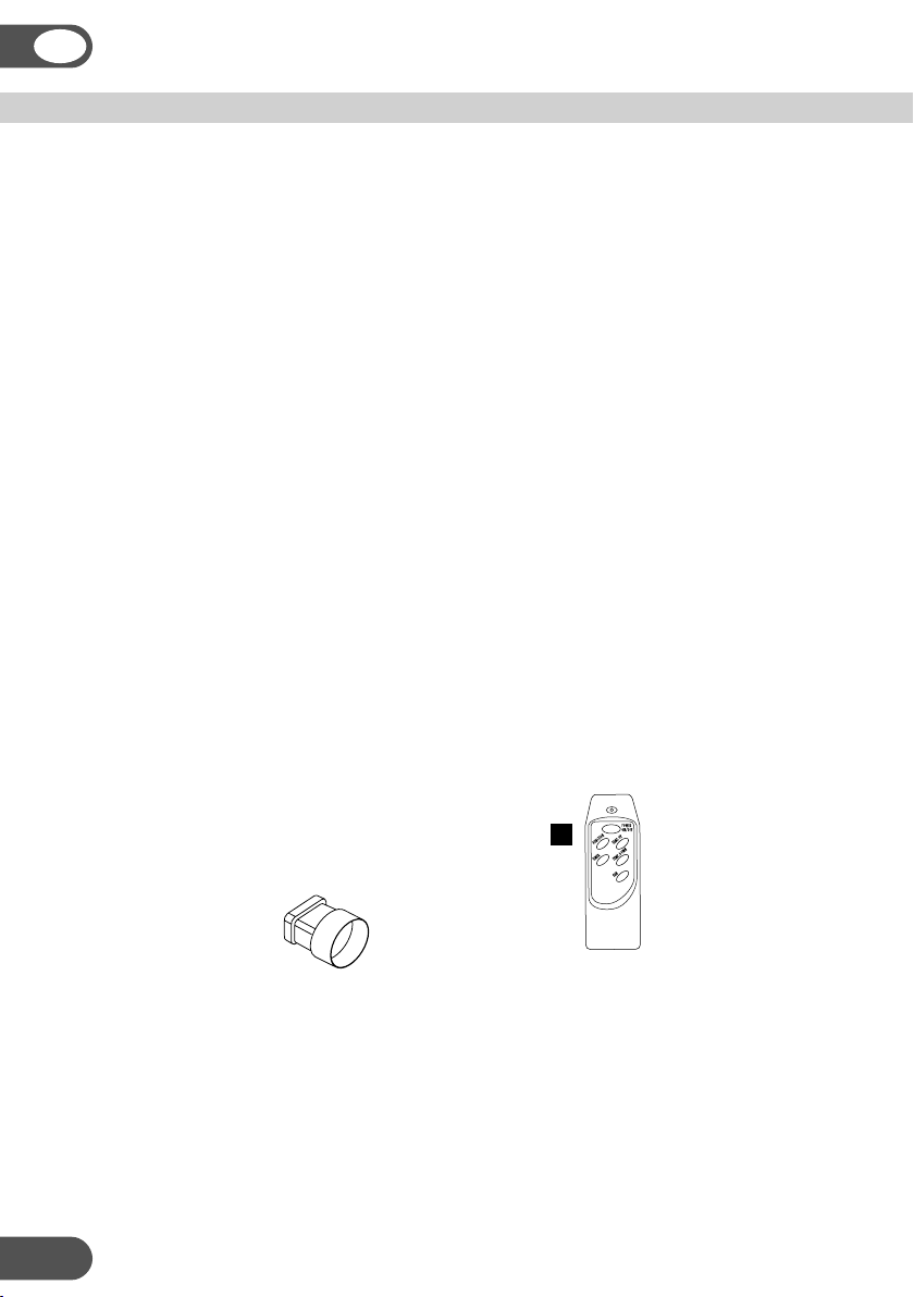
13. Hose adapter
14. Window/wall adapter
15. Cap
16. Exhaust hose
17. Water tube
18. Remote control
18
2
Page 3

THANK YOU
Thank you for choosing this innovative Amcor air conditioner. We suggest that you
keep this manual in a safe place for future reference. It describes the many benefits
and advanced features this unique product has to offer. Before you use your air
conditioner you should carefully read these instructions to maximise this product’s
performance.
For over 50 years Amcor has specialised in complete indoor environmental control,
manufacturing and marketing; dehumidifiers, portable air conditioners, coolers, air
purifiers, ionisers and aroma therapy scent diffusers. These world class products
incorporate the latest technological developments.
SAFETY INSTRUCTIONS
IMPORTANT!
• The unit is designed for indoor operation.
• Rating: This unit must be connected to a 220-240 V / 50 Hz earthed outlet.
• The installation must be in accordance with regulations of the country where the
unit is used.
If you are in any doubt about the electrical installation, have it checked and if
necessary modified by a qualified electrician.
GB
• The air conditioner is safe. However, as with other electrical appliances, use it
with care.
• Keep out of the reach of children.
• Do not clean the unit by spraying it or immersing it in water.
• Do not insert any object into the openings of the unit.
• Disconnect it from the mains before cleaning the unit or any of its components.
• Never connect the unit to an electrical outlet using an extension cord. If an outlet
is not available, one should be installed by a licensed electrician.
3
Page 4
GB
WARNING
• Never operate this appliance if it has a damaged cord or plug. Do not lead the
cord over sharp edges.
• A damaged supply cord should be replaced by the manufacturer, its service agent
or a qualified person in order to avoid a hazard.
• Any service other than regular cleaning or wick replacement should be performed
by an authorized service representative. Failure to do so could result in a loss of
warranty.
POSITIONING
This unit is portable and can easily be moved from one room to another. In doing
so keep this in mind:
• The air conditioner must stand upright on an even surface.
• Position not (near) bath, douche or other wet or damp area.
• Keep for free air circulation at least 50 cm free from any obstacle or curtains.
4
Page 5
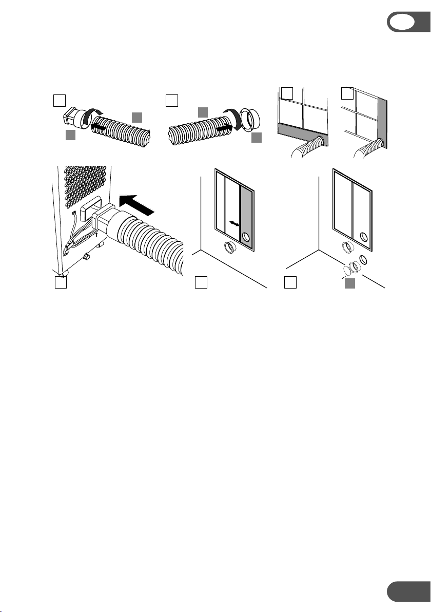
• Put the exhaust hose into the round side of the exhaust hose adapter (13) (fig. 1).
• Put the wall/window adapter (14) onto the exhaust hose (fig. 2).
• Connect the hose with the rectangular end to the air conditioner (fig. 4).
GB
1 2
16
13
4
3a
16
14
56
3b
15
Using the foam.
Place the foam with the hole (11), if needed together with the foam extension (10),
in the window and close this as far as possible to refrain the warm air from reentering the room (fig. 5). Depending on how the window opens, horizontally
(fig. 3a) or vertically (fig. 3b).
Pass the hose through the opening in the foam (11).
Permanent hole in glass or wall.
Place the wall/window connector (14) in the hole with diameter 130 millimetre
(fig. 6). Connect the hose with the rectangular end to the air conditioner (fig. 4).
Use the cap (15) to close the opening when the air conditioner is not used.
Important
The flexible exhaust hose can be extended from 300 to 1500 mm for mounting.
This length has been designed especially according to the specifications of the air
conditioner. Do not use an extension or exchange for a different hose as that may
lead to malfunctioning.
The exhaust air must flow freely, any blockage can lead to overheating of the air
conditioner. Take care to prevent any bow or bend in the exhaust hose.
5
Page 6
GB
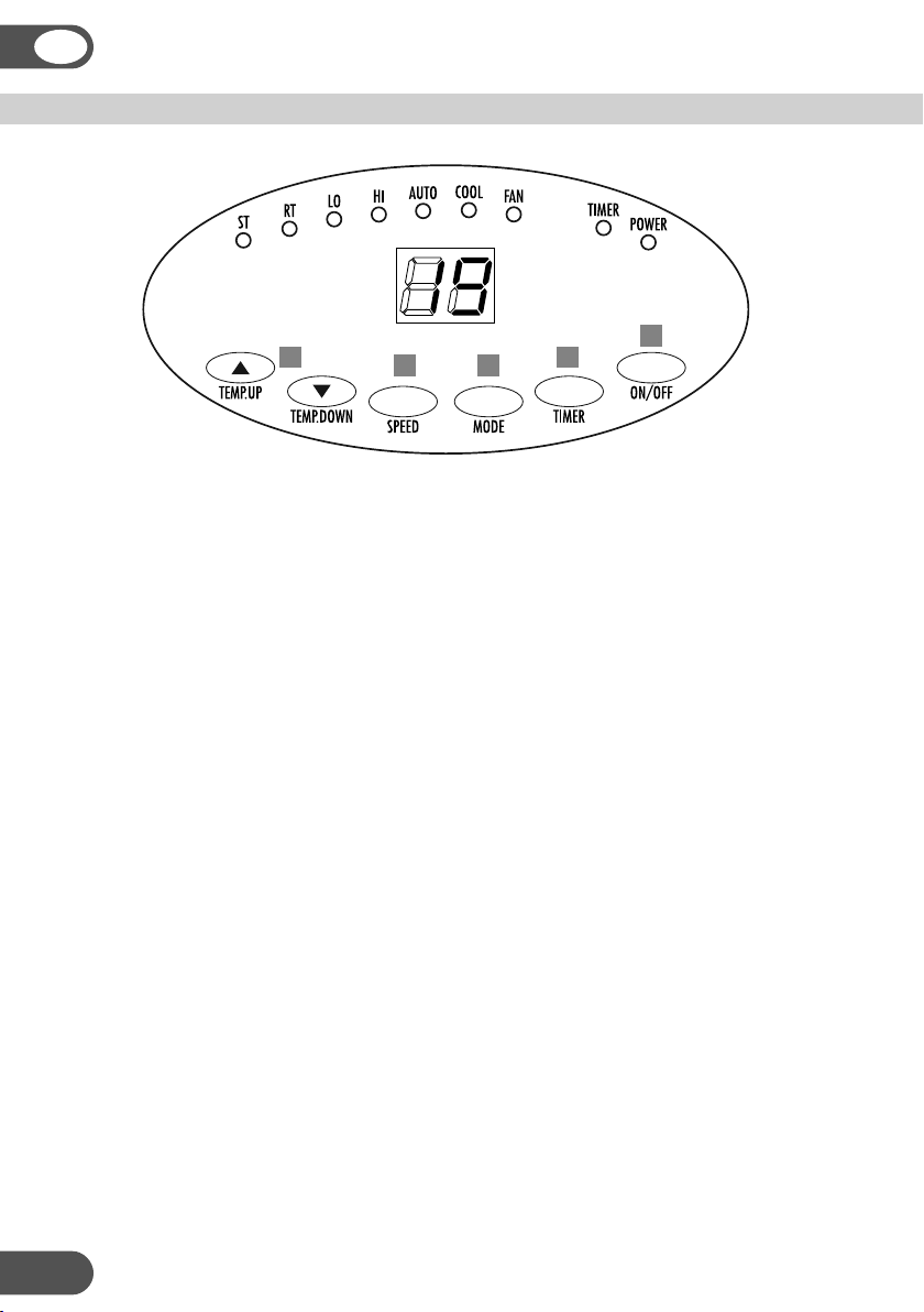
OPERATION
5
4
3
2
1
1. ON/OFF
Press the ON/OFF-button to switch the unit on or off. The unit selects the
operating mode depending on the room temperature:
- with an ambient temperature higher than 23 °C, cooling mode is selected
- is the ambient temperature between 20 °C and 23 °C, then will fan mode be active.
2. Timer button
Use this button to set a working time between 1 and 12 hours. The TIMER LED will
be on. The unit switches off when the set time has run down.
3. Mode switch
Select with this button the required operating mode: automatic, cooling or fan.
The corresponding LED will lit: AUTO, COOL or FAN.
4. Fan speed
Select with this button the fan speed, the corresponding LED will lit: LO - low ,
HI - high.
5. Temperature selection
Set the temperature that must be maintained (in the range from 18 °C to 32 °C) with
the buttons TEMP.UP and TEMP.DOWN. The display will show the setting.
Digital display
When the unit is ON the display shows the room temperature, RT LED is on. Press
button TEMP.UP or TEMP.DOWN to see the set temperature, the ST LED is then
on. After a few of seconds the room temperature will be displayed and the RT LED
will be on again.
6
Page 7
Remote control
The air conditioner can be operated with the remote control. Two AAAbatteries are required to use the remote control. Point the remote control
hand set towards the control panel of the unit and press the relevant button,
the red LED on the hand set will flash whenever a button is pressed.
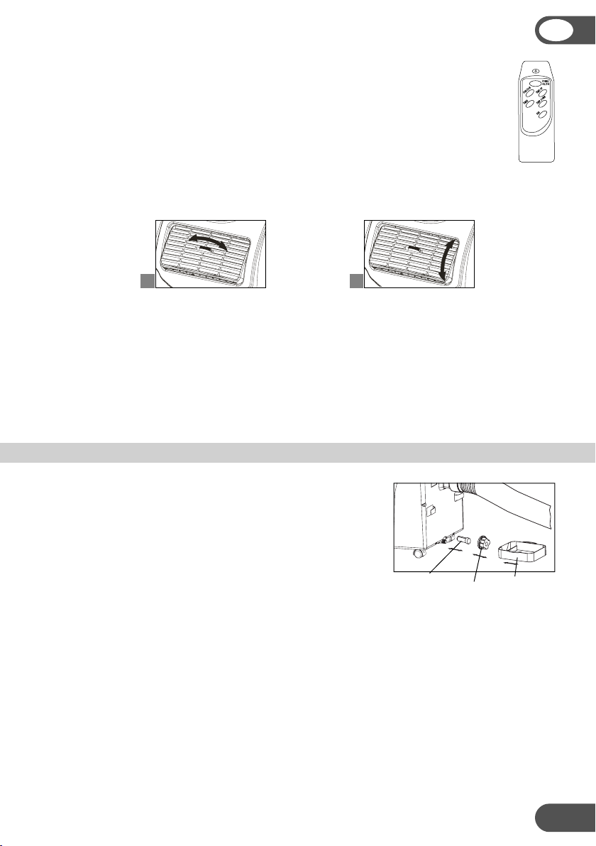
Air flow
a. Turn the roller to control the air flow direction of the vertical louvres.
b. Move the air vent directly to adjust the air flow direction of the horizontal louvres.
a b
Notices:
• The compressor has been set so that it starts functioning three minutes after the
(re)start of the air conditioner.
• The cooling will switch off when the room temperature is lower than the set
one. Ventilation will however continue to work on the set level. When the room
temperature rises above the selected value, the cooling will work again.
GB
EMPTYING THE INTERNAL WATER CONTAINER
When the water container is full, the compressor and
the ventilator stop functioning, the POWER LED will
flash.
Switch off the unit and remove the plug from the
mains.
• Place the water tray flat on the floor under the drain.
• Remove the drain knob.
• Remove the rubber plug and fill the water tray then replace the plug to stop
the water flow. Empty the tray and repeat this process until all water has been
removed.
• Replace the rubber plug and the drain knob, plug the unit in and switch on. The
POWER LED should not flash any longer.
Rubber plug Water tray
Drain knob
7
Page 8

GB
PERMANENT DRAINAGE
Switch off the unit and remove the plug from the mains.
• Remove the drain knob and the rubber plug.
• Connect the correct water tube onto the water outlet.
• Place the other end in a normal drain.
• Make sure that the tube is free from twists and bends.
The tube must incline over its entire length.
Dehumidification
If the unit will be used mainly as dehumidification, do not connect the exhaust hose
and let the warm air return in the room. Continuous drainage is then convenient
and more efficient.
CLEANING
First of all switch off the unit and pull the plug.
Clean the housing with a soft, damp cloth. Never use aggressive chemicals, petrol,
detergents or other cleansing solutions.
Filter
The single layer screen filter cleans the circulated air. The filter needs to be cleaned
regularly with a vacuum cleaner to avoid blocking the air flow.
Notice! Never use the air conditioner without filter.
8
Page 9

STORAGE
See the instructions "Emptying the water container" on page 7.
• Drain the condensed water completely.
• Clean (or replace) the filter.
• Put the unit on a sunny day in fan mode for a couple of
hours to ensure that the inside becomes completely dry.
• Store the power cable as shown, protect the unit against
dust and store in a dry place not accessible for children.
TROUBLE SHOOTING
Never try to repair or dismantle the air condition yourself. Incompetent repairs result in loss of warranty
and can endanger the user and the property.
Problem Cause Solution
The air
conditioner does
not function.
The air
conditioner does
not seem to
perform.
The unit is noisy. Unit stands uneven. Place on an even, solid surface (less
The compressor
does not work.
The remote
control does not
function.
To correct problems that have not been described in the table and/or if the recommended solutions fail
to solve the problem, contact an authorized service centre.
Cable storage
No power supply. Connect to a functioning outlet and switch on.
Is the LCD light fl ashing. Empty the internal water container.
Timer function is active. Deactivate TIMER function.
In direct sunlight. Close curtains.
Windows or doors open, many
people or a heat source in the room.
Dirty filter. Clean or replace the fi lter(s).
Air inlet or air outlet blocked. Remove the blockage.
Room temperature lower than the
selected value.
The overheat protection is probably
activated.
Distance too great. Make sure the remote control is correctly
Remote control signal not detected
by the control panel.
The batteries are drained. Replace the batteries.
Close doors and windows, place an extra air
conditioner.
Change temperature selection.
vibrations).
Wait 3 minutes until the temperature has
decreased, then turn on the unit again.
aimed at the control panel.
GB
9
Page 10

GB
TECHNICAL DATA
Model AMC
7KE-410
Cooling capacity
BTU/h 6500 8300 9600
kW 1.9 2.4 2.8
AMC
10KE-410
AMC
12KE-410
Mains 220–240 V / 50 Hz / 1Ph
Power consumption W 690 830 1030
Current A 3 3.7 4.5
Dehumidification L/24h 24 28.8 36
Air delivery m
Recommended room size m
3
/h 300 350 350
2
12 18 24
Refrigerant R410A
Compressor rotary
Fan speeds 2
Thermostat °C 18 – 32
Timer h 1 – 12
Dimensions (W x H x D) mm 377 x 750 x 400
Weight kg 29 30 32
Subject to modifications without prior notice.
Please refer to the rating label for greater precision.
Reminder:
Waste electrical products must not be disposed of with household waste.
This product should be taken to your local recycling centre for safe treatment.
10
Page 11

Hong Kong
Ltd
Amcor
2007, Tower 6, The Gateway,
Suite
City, 9 Canton Road,
Harbour
Tsim Sha Tsui, Kowloon,
Kong
Hong
Tel: +852 2997 6865
Fax: +852 2997 6091
amcorhk@amcorgroup.com
Email:
United
Kingdom
Ltd
Amcor
9 Ryan Drive, West Cross Centre,
West Road, Brentford,
Great
Middlesex,
United
Tel: +44 20 8560 4141
Fax: +44 20 8232 8814
Email:
USA
Amcor
685A
New
United
Tel: +1 201 460 8100
Fax: +1 201 460 9481
Email:
The Netherlands
Amcor
Anton
1422
The
Tel: +31 297 560 079
Fax: +31 297 523 062
Email: amcorex@amcorgroup.com
Israel
Amcor
1 Sapir St.,
P.O.
Hertzeliya
Israel
Tel: +972 9951 5351
Fax: +972 9958 5650
Email:
Singapore
Amcor
545
#13-02,
Singapore
Tel: +65 6297 9881
Fax: +65 6297 8891
Email:
TW8 9ER,
Kingdom
amcoruk@amcorgroup.com
Inc.
Gotham Parkway, Carlstadt,
Yersey 07072,
States of America
amcorusa@amcorgroup.com
B.V.
Philipsweg 9-11,
AL Uithoorn,
Netherlands
International Ltd
Box 12001
Pituach,
amcoril@amcorgroup.com
Investments (Singapore) Pte Ltd
Orchard Road,
Far East Shopping Centre,
238882
amcorsg@amcorgroup.com
China
Shan Xia Industrial Development Zone,
Heng Li
Town, Dongguan City,
Guangdong Province, China
Plant One - Amcor (China) Ltd
Tel: +86 769 8372 1090
Fax: +86 769 8372 1790
Email: amcorcn@amcorgroup.com
Two - Amcor Appliances Ltd
Plant
Tel: +86 769 8372 1970
Fax: +86 769 8372 1790
Email: amcorappl@amcorgroup.com
0
52
42
13
1
9
C
MA
Page 12

Page 13

PARTS
GB
5
1
1. Control panel
2. Air outlet
3. Handle
4. Casters
11
2
3
4
10
16
6
7
8
9
5. Air filter
6. Air inlet
7. Exhaust air outlet
8. Cord hanger
9. Water stopper (plug inside)
12
13
14
15
17
10. Foam extension
11. Foam with hole
12. Water tray
13. Hose adapter
14. Window/wall adapter
15. Cap
16. Exhaust hose
17. Water tube
2
Page 14

THANK YOU
Thank you for choosing this innovative Amcor air conditioner. We suggest that you
keep this manual in a safe place for future reference. It describes the many benefits
and advanced features this unique product has to offer. Before you use your air
conditioner you should carefully read these instructions to maximise this product’s
performance.
For over 50 years Amcor has specialised in complete indoor environmental control,
manufacturing and marketing; dehumidifiers, portable air conditioners, coolers, air
purifiers, ionisers and aroma therapy scent diffusers. These world class products
incorporate the latest technological developments.
SAFETY INSTRUCTIONS
IMPORTANT!
• The unit is designed for indoor operation.
• Rating: This unit must be connected to a 220-240 V / 50 Hz earthed outlet.
• The installation must be in accordance with regulations of the country where the
unit is used.
If you are in any doubt about the electrical installation, have it checked and if
necessary modified by a qualified electrician.
GB
• The air conditioner is safe. However, as with other electrical appliances, use it
with care.
• Keep out of the reach of children.
• Do not clean the unit by spraying it or immersing it in water.
• Do not insert any object into the openings of the unit.
• Disconnect it from the mains before cleaning the unit or any of its components.
• Never connect the unit to an electrical outlet using an extension cord. If an outlet
is not available, one should be installed by a licensed electrician.
WARNING
• Never operate this appliance if it has a damaged cord or plug. Do not lead the
cord over sharp edges.
• A damaged supply cord should be replaced by the manufacturer, its service agent
or a qualified person in order to avoid a hazard.
• Any service other than regular cleaning or wick replacement should be performed
by an authorized service representative. Failure to do so could result in a loss of
warranty.
3
Page 15

4
Page 16

POSITIONING
This unit is portable and can easily be moved from one room to another. In doing
so keep this in mind:
• The air conditioner must stand upright on an even surface.
• Position not (near) bath, douche or other wet or damp area.
• Keep for free air circulation at least 50 cm free from any obstacle or curtains.
GB
Installation
1
16
• Put the exhaust hose into the round side of the exhaust hose
adapter (13) (fig. 1).
• Put the wall/window adapter (14) onto the exhaust hose
(fig. 2).
13
2
16
• Connect the hose with the rectangular end to the air
conditioner (fig. 4).
a
3
b
3
4
5 6
15
Using the foam.
Place the foam with the hole (11), if needed together with the foam extension (10),
in the window and close this as far as possible to refrain the warm air from reentering the room (fig. 5). Depending on how the window opens, horizontally
(fig. 3a) or vertically (fig. 3b).
Pass the hose through the opening in the foam (11).
Permanent hole in glass or wall.
Place the wall/window connector (14) in the hole with diameter 130 millimetre
(fig. 6). Connect the hose with the rectangular end to the air conditioner (fig. 4).
Use the cap (15) to close the opening when the air conditioner is not used.
14
Important
The flexible exhaust hose can be extended from 300 to 1500 mm for mounting.
This length has been designed especially according to the specifications of the air
conditioner. Do not use an extension or exchange for a different hose as that may
lead to malfunctioning.
The exhaust air must flow freely, any blockage can lead to overheating of the air
conditioner. Take care to prevent any bow or bend in the exhaust hose.
5
Page 17

GB
OPERATION
1 2 3 4
3 2 1
ON/OFF and timer function
Turn the control [1] to switch the unit on or off. When the unit is on, LED-1 is on.
Timer function
Use control [1] to set a working time between 1 and 8 hours. The unit switches off
when the set time has run down.
Mode selection and speed setting
Select with control [2] the required operating mode cooling or fan mode. The
corresponding LED (2 or 3) will lit.
Select the larger symbol position for high or low fan speed, or low or strong cooling.
Thermostat setting
Turn control [3] to maintain the temperature level in combination with cooling.
Notices:
• The compressor has been set so that it starts functioning three minutes after the
(re)start of the air conditioner.
• The cooling will switch off when the room temperature is lower than the set
one. Ventilation will however continue to work on the set level. When the room
temperature rises above the selected value, the cooling will work again.
Air flow
Turn the roller to control the air flow direction of the vertical
louvres.
Move the air vent directly to adjust the air flow direction of the
horizontal louvres.
6
Page 18

When the water container is full, the compressor and
the ventilator stop functioning, LED [4] will lit.
Switch off the unit and remove the plug from the
mains.
• Place the water tray flat on the floor under the drain.
• Remove the drain knob.
• Remove the rubber plug and fill the water tray then replace the plug to stop
the water flow. Empty the tray and repeat this process until all water has been
removed.
• Replace the rubber plug and the drain knob, plug the unit in and switch on. The
LED [4] should now be out.
GB
7
Page 19

GB
CLEANING
First of all switch off the unit and pull the plug.
Clean the housing with a soft, damp cloth. Never use aggressive chemicals, petrol,
detergents or other cleansing solutions.
Filter
The single layer screen filter cleans the circulated air. The filter needs to be cleaned
regularly with a vacuum cleaner to avoid blocking the air flow.
• Push the two clips on the filter housing downward and pull the filter housing
forward and out of the unit.
• Remove the rear retainer from the housing by gently prising it from the retaining
clips.
• Insert the screen filter aligning the two cut outs with the clips on the top of the
filter housing.
• Reverse the procedure to re-fit the housing in the air conditioner.
Notice! Never use the air conditioner without filter.
STORAGE
See the instructions "Emptying the water container" on page 7.
• Drain the condensed water completely.
• Clean (or replace) the filter.
• Put the unit on a sunny day in fan mode for a couple of
hours to ensure that the inside becomes completely dry.
• Store the power cable as shown, protect the unit against
dust and store in a dry place not accessible for children.
Cable storage
ELECTRIC CONNECTION
Important: how to wire a 13 amp plug
The wires in the mains lead on this appliance are
coloured in accordance with the following code:
GREEN AND YELLOW – EARTH BLUE – NEUTRAL BROWN – LIVE
As the colours may not correspond with the markings
identifying the terminals in your plug proceed as
BLUE
Neutral
follows:
GREEN AND YELLOW wire must be connected to the
The
terminal in the plug which is marked with the letter
E or with the earth symbol
or coloured green and
yellow.
The BLUE wire must be connected to the terminal marked N or coloured black.
The BROWN wire must be connected to the terminal marked L or coloured red.
Cord clamp
GREEN/YELLOW
Earth
8
BROWN
Live
FUSE
13 Amp
Page 20

TROUBLE SHOOTING
Never try to repair or dismantle the air conditioner yourself. Incompetent repairs result in
loss of warranty and can endanger the user.
Problem Cause
The unit does
not function
The unit does
not seem to
perform
The unit is noisy Unit stands uneven Place on even surface (
The compressor
does not work
TECHNICAL DATA
Solution
Check the plug fuse. Check
the mains outlet by connecting
another appliance
Water container indicator is on Empty water container
Room temperature outside
operating temperature range
In direct sunlight Close curtains
Windows or doors open, many
people or heat source in room
Dirty filter Clean or replace filter
Air inlet or air outlet blocked Remove blockage
Room temperature lower than
selected value
Overheat protection probably
activated
Connect to a functioning outlet and
switch on
Change temperature selection
Wait until room temperature lowers
less vibrations
GB
)
Model AMC
7KM-410
Cooling capacity
measured conform EN 14511
BTU/h 6500 8300 9600
kW 1.9 2.4 2.8
AMC
10KM-410
AMC
12KM-410
Mains 220–240 V / 50 Hz / 1 phase
Power consumption W 690 830 1030
Current A 3.0 3.7 4.5
Dehumidification L/24h 24 28.8 36
3
Air delivery m
Recommended room size m
/h 300 350 350
2
12 18 24
Refrigerant type R410A
Compressor rotary
Fan speeds 2
Thermostat °C 18 – 32
Timer h 1 – 8
Dimensions (W x H x D) mm 377 x 750 x 400
Weight kg 29 30 32
Subject to modifications without prior notice. Please refer to the rating label for greater precision.
9
Page 21

GB
AMCOR GUARANTEE PROCEDURE
Amcor products have a lower than industry norm failure rate, as we have strict quality
control in our factory. However we are not 100% perfect and occasionally units can fail.
When they do we have a simple returns procedure.
All Amcor products are guaranteed for one-year from date of purchase, on a back to
base principle. A copy of our guarantee page is attached.
Consumers need to keep the till receipt as proof of purchase.
The Amcor Help line number for the UK 020 8 560 4141 appears on the back of each
unit and in the instruction manual.
If a consumer believes the unit to be faulty the first course of action is to phone the
Help line 0208 560 4141. A trained engineer will speak to them. Often we find that this
eliminates 95% of no fault found, as the customer may not be using the product in the
correct manner.
If the engineer believes the unit may be faulty, Amcor will arrange collection by a carrier
from the consumer. The product must be boxed and amply protected to avoid cosmetic
damage in transit. If the consumer is unable to be present to allow for collection, the
boxed unit can be collected from store. Of course Amcor pay the carriage charge.
On reaching Amcor the unit is checked, repaired or replaced, re-boxed and returned
again by carrier to an agreed return address. This process usually takes 5 – 7 working
days.
If the customer returns to store and claims the unit to be faulty we would ask that you
carry out the same procedure as above, particularly with air conditioners, rather than
simply exchange or refund. Again this eliminates the risk that the consumer is not using
the product correctly. However goods returned faulty inside 28 days can be exchanged
– usually faulty goods “dead on arrival” will be returned to store by the consumer within
a few days.
To exchange or refund DOA goods within 28 days stores must call Amcor on 020 8 560
4141 (Monday – Friday 09.00 – 17.30 hrs.) for an authorisation number. If goods need
to be exchanged over a week-end (or late evening) stores must contact Amcor on the
next working day. Amcor will require store details, product details and date of purchase/
return.
Goods returned under 28 day agreement that are found to have significant wear & tear
will not be credited; consequently stores must check purchase and return dates.
Goods returned outside 28 days of purchase will not be authorised for return to Amcor.
Instead we will collect / repair / return the unit under our normal guarantee procedure.
Outside of the guarantee period Amcor are able to service or repair units for a
reasonable cost. Consumers can get details of the cost from the Help line number.
Consumables such as activated carbon filters can be bought directly from Amcor;
payment can be by cheque or credit card.
This guarantee is in addition to the customers’ statutory rights.
10
Page 22

YOUR GUARANTEE
DOMESTIC AIR CONDITIONERS
If this product is found to be defective as a result of faulty materials or workmanship
within one year from date of purchase, it will be repaired or replaced free of charge.
This guarantee is subject to the following terms:
Amcor Limited., must be notified of the fault
Proof of purchase must be presented to Amcor’s nominated representative
The warranty will be void if the product is modified, misused or repaired
by an unauthorised person
The guarantee does not cover accidental damage, misuse,
or consumable items such as filters
The guarantee after repair or replacement will not be extended
beyond the original one-year period
All replacement parts or units will be new or reconditioned
Parts or units, which are replaced, become the property of Amcor Limited
Amcor Limited disclaims any liability for incidental or consequential damages
The warranty applies for the use of the product in UK.
GB
This GUARANTEE is in addition to your Statutory Rights.
Creating Quality Environments
AMCOR LIMITED • 9 Ryan Drive • West Cross Centre • Great West Road • Brentford
Middlesex • TW8 9ER • UK
For Customer Support Call: 020 8 560 4141
Reminder:
Waste electrical products must not be disposed of with household waste.
This product should be taken to our local recycling centre for safe treatment.
11
Page 23

Hong Kong
Ltd
Amcor
2007, Tower 6, The Gateway,
Suite
City, 9 Canton Road,
Harbour
Tsim Sha Tsui, Kowloon,
Kong
Hong
Tel: +852 2997 6865
Fax: +852 2997 6091
amcorhk@amcorgroup.com
Email:
United
Kingdom
Ltd
Amcor
9 Ryan Drive, West Cross Centre,
West Road, Brentford,
Great
Middlesex,
United
Tel: +44 20 8560 4141
Fax: +44 20 8232 8814
Email:
USA
Amcor
685A
New
United
Tel: +1 201 460 8100
Fax: +1 201 460 9481
Email:
The Netherlands
Amcor
Anton
1422
The
Tel: +31 297 560 079
Fax: +31 297 523 062
Email:
Israel
Amcor
1 Sapir St.,
P.O.
Hertzeliya
Israel
Tel: +972 9951 5351
Fax: +972 9958 5650
Email:
Singapore
Amcor
545
#13-02,
Singapore
Tel: +65 6297 9881
Fax: +65 6297 8891
Email:
TW8 9ER,
Kingdom
amcoruk@amcorgroup.com
Inc.
Gotham Parkway, Carlstadt,
Yersey 07072,
States of America
amcorusa@amcorgroup.com
B.V.
Philipsweg 9-11,
AL Uithoorn,
Netherlands
amcorex@amcorgroup.com
International Ltd
Box 12001
Pituach,
amcoril@amcorgroup.com
Investments (Singapore) Pte Ltd
Orchard Road,
Far East Shopping Centre,
238882
amcorsg@amcorgroup.com
China
Shan Xia Industrial Development Zone,
Heng Li
Town, Dongguan City,
Guangdong Province, China
Plant One - Amcor (China) Ltd
Tel: +86 769 8372 1090
Fax: +86 769 8372 1790
Email: amcorcn@amcorgroup.com
Two - Amcor Appliances Ltd
Plant
Tel: +86 769 8372 1970
Fax: +86 769 8372 1790
Email: amcorappl@amcorgroup.com
02
3
42
13
1
9
C
MA
 Loading...